

PRIME MOVER RTX35 RTX45 FORK Truck Workshop Service Repair M
What's Included?
Fast Download Speeds
Online & Offline Access
Access PDF Contents & Bookmarks
Full Search Facility
Print one or all pages of your manual
Part no: 310428-000 Date: July 30, 2001
Master Service Manual
Read and observe all warnings on this unit
before operating it.
DO NOT operate this equipment unless all
factory installed guards and shields are
properly secured in place.
WARNING
WARNING
F
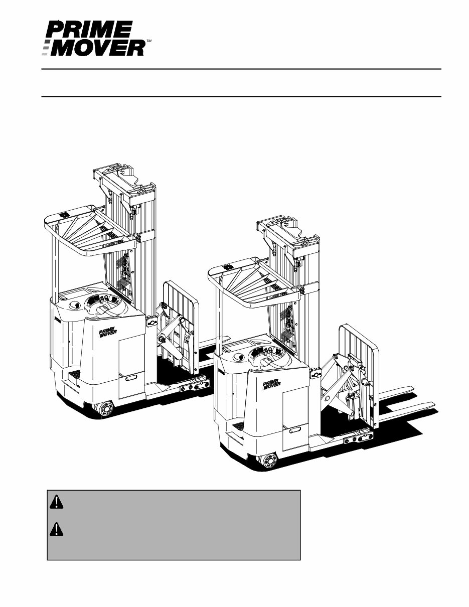
RTX35/45
Electric Stand-Up Rider Truck
Effective Serial Number RTX3530317001 - UP
+
-
1
0
1 /2
+
-
1
0
1/2

Prime-Mover is a trademark of BT Prime-Mover Inc.,
© 2001 BT Prime-Mover Inc., Muscatine, Iowa.
All Rights Reserved.

BT Prime-Mover Standard Codes
F-code Section C-code
Version no T-code
000
© BT Prime-Mover Inc.
1
Service Manual 2001-03-15
BT Prime-Mover Standard Codes
B-Code = Business area
F-Code = Product family
T-Code = Product type
C-Code = Component function
Worksheet standard
W-Code = Working code
R-Code = Reason code
SO-Code = Assortment
C-Code List
No Function Group C-Code
0 Chassis 0000
1 Drive Motor 1000
2 Drive Gear / Transmission 2000
3 Brake / Wheel System 3000
4 Steering System 4000
5 Electrical System 5000
6 Hydraulic / Pneumatic System 6000
7 Operating Function-lifting Mast / Cylinders 7000
8 Peripheral / Installation Equipment 8000
9 Options / Attachments 9000

000
Version no T-code
F-code Section C-code
BT Prime-Mover Standard Codes
2
Service Manual 2001-03-15

© BT Prime-Mover Inc.
3
Table of Contents
BT Prime-Mover Standard Codes ................................................................ 1
Warning Symbols ......................................................................................... 13
Warning Levels ......................................................................................... 13
Prohibitory Symbols .................................................................................... 14
Ordinance Symbols .................................................................................. 14
Safety ............................................................................................................ 15
General Safety .......................................................................................... 15
Battery Safety ............................................................................................... 19
Static Safety .................................................................................................. 23
Welding Safety ............................................................................................. 24
Introduction, Service Manual ...................................................................... 27
Contents, Section M ..................................................................................... 29
Machine Information ................................................................................. 29
General Product Information ...................................................................... 31
Truck Presentation .................................................................................... 31
Main Components ..................................................................................... 37
Grease Point Location .............................................................................. 40
Mast Adjustment Points ............................................................................ 41
Inch (SAE) and Metric Fasteners ............................................................... 43
Introduction ............................................................................................... 43
Nomenclature, Threads ............................................................................ 44
Strength Identification ............................................................................... 45
Conversion of Metric and English Units .................................................... 52
Technical Service Data ................................................................................ 55
Ordering Spare Parts ................................................................................... 59
Contents, Section P ..................................................................................... 61
Planned Maintenance ............................................................................... 61
Introduction, Maintenance .......................................................................... 63
Safe Jacking Procedure ............................................................................ 64
Lubricants ................................................................................................. 65

© BT Prime-Mover Inc.
4
Table of Contents
Service Schedule ......................................................................................... 67
Planned Maintenance Schedule ............................................................... 67
Planned Maintenance Procedures ............................................................ 72
Lubrication Chart ......................................................................................... 79
Oil and Grease Specifications .................................................................... 81
Approved Oils and Grease ....................................................................... 81
Contents, Section S ..................................................................................... 83
Service Instructions .................................................................................. 83
Troubleshooting Guidelines ....................................................................... 85
General ..................................................................................................... 85
Electrical ................................................................................................... 87
Hydraulic ................................................................................................... 92
Definitions ................................................................................................. 93
Chassis ......................................................................................................... 95
General ..................................................................................................... 95
Top Console ............................................................................................. 96
Motor Compartment Door ......................................................................... 97
Left Side Panel (Exterior) .......................................................................... 98
Left Operator Compartment Panel ........................................................... 100
Main Electronic Card Panel ..................................................................... 101
Floor Board .............................................................................................. 102
Clipboard ................................................................................................. 103
Battery Retainer Plates and Rollers .......................................................... 105
Battery Retainer Plates ............................................................................ 106
Battery Rollers ......................................................................................... 106
Mounting Points .......................................................................................... 107
Drive Motor .............................................................................................. 107
Pump Motor ............................................................................................. 110
Transmission ........................................................................................... 114
Driver Controls ............................................................................................ 117
Handle Interface Module .......................................................................... 119
Control Handle ......................................................................................... 120
Brake Pedal (RTX35) ................................................................................... 123
Pedal Removal ........................................................................................ 124
Pedal Bearing Replacement .................................................................... 125
Pedal Adjustment ..................................................................................... 125

© BT Prime-Mover Inc.
5
Table of Contents
Brake Pedal (RTX45) ................................................................................... 126
Pedal Removal ........................................................................................ 127
Pedal Bearing Replacement .................................................................... 128
Pedal Adjustment ..................................................................................... 128
Internal Fittings ........................................................................................... 129
Operator Fan ........................................................................................... 129
Guards .......................................................................................................... 131
Overhead Guard ...................................................................................... 131
Decals ........................................................................................................... 133
Decal with Protective Sheet ..................................................................... 133
Decal without Protective Sheet ................................................................ 133
Steering Motor ............................................................................................. 137
Removal ................................................................................................... 137
Installation ................................................................................................ 138
Steering Motor Gear Replacement .......................................................... 139
Fan Motor ..................................................................................................... 141
Upper Electrical Compartment Fan ......................................................... 141
Operator Fan ........................................................................................... 142
Motor Maintenance
Schedule/Troubleshooting ......................................................................... 143
General Information ................................................................................. 143
Operating Conditions ............................................................................... 143
Troubleshooting ....................................................................................... 144
Pump Motor (RTX35) ................................................................................... 151
Component Repair ................................................................................... 152
Motor Inspection ...................................................................................... 154
Pump Motor (RTX 45) .................................................................................. 161
Component Repair ................................................................................... 162
Motor Inspection ...................................................................................... 164
Drive Motor .................................................................................................. 165
Motor Disassembly .................................................................................. 166
Motor Inspection ...................................................................................... 167
Transmission. .............................................................................................. 169
Axle Sealing Ring .................................................................................... 171
Leakage ................................................................................................... 173

© BT Prime-Mover Inc.
6
Table of Contents
Wheel Bolt ............................................................................................... 175
Electromagnetic Brake ............................................................................... 177
Removal ................................................................................................... 177
Installation ................................................................................................ 179
Adjustments ............................................................................................. 180
Coil Check On Brake ............................................................................... 181
Electromagnetic Brake, Armature and Magnetic Coil .............................. 181
Brake Friction Plate ................................................................................. 182
Drive Wheel .................................................................................................. 183
Removal ................................................................................................... 183
Installation ................................................................................................ 184
Tire Pressing Procedure .......................................................................... 185
Non-Braking Caster Assembly .................................................................. 187
Caster Pivot ............................................................................................. 189
Thrust Bearing ......................................................................................... 191
Caster Springs ......................................................................................... 193
Caster Stops ............................................................................................ 195
Non-Braking Caster Wheels ....................................................................... 197
Removal ................................................................................................... 197
Installation ................................................................................................ 198
Braking Caster Assembly ........................................................................... 199
Removal ................................................................................................... 201
Braking Caster Wheel Assembly ............................................................... 203
Removal ................................................................................................... 204
Installation ................................................................................................ 205
Tandem Load Wheels ................................................................................. 207
Removal ................................................................................................... 208
Installation ................................................................................................ 209
Single Load Wheels .................................................................................... 211
Removal ................................................................................................... 212
Installation ................................................................................................ 213
Steering Wheel ............................................................................................ 215
Removal ................................................................................................... 215
Installation ................................................................................................ 216
Steer Tach .................................................................................................... 217

© BT Prime-Mover Inc.
7
Table of Contents
Removal ................................................................................................... 217
Installation ................................................................................................ 218
Steering Bearing ......................................................................................... 219
Removal ................................................................................................... 220
Installation ................................................................................................ 220
Electrical Functions .................................................................................... 221
General .................................................................................................... 221
Start Up .................................................................................................... 225
Steering Components .............................................................................. 229
Brake Release ......................................................................................... 235
Travel Request, Forks First ..................................................................... 237
Travel Request, Forks Trailing ................................................................. 241
Plug Braking ............................................................................................ 245
12-Volt Power Supply .............................................................................. 249
7.35-Volt Power Supplies ........................................................................ 251
Limit Switches .......................................................................................... 253
Height Indicator ........................................................................................ 257
Drive Motor Brush Wear Indicator Switches ............................................ 259
Pump Motor Brush Wear Indicator Switches ........................................... 260
Safety Check ........................................................................................... 261
Shunt Power Cable .................................................................................. 263
Electrical Symbols ...................................................................................... 271
Electrical Schematics ................................................................................. 273
Circuit Diagram 1 (12) .............................................................................. 273
Circuit Diagram 2 (12) .............................................................................. 274
Circuit Diagram 3 (12) .............................................................................. 275
Circuit Diagram 4 (12) .............................................................................. 276
Circuit Diagram 5 (12) .............................................................................. 277
Circuit Diagram 6 (12) .............................................................................. 278
Circuit Diagram 7 (12) .............................................................................. 279
Circuit Diagram 8 (12) .............................................................................. 280
Circuit Diagram 9 (12) .............................................................................. 281
Circuit Diagram 10 (12) ............................................................................ 282
Circuit Diagram 11 (12) ............................................................................ 283
Circuit Diagram 12 (12) ............................................................................ 284
Battery .......................................................................................................... 285
Removal ................................................................................................... 285
Installation ................................................................................................ 285
Battery Maintenance ................................................................................ 286
Storage .................................................................................................... 288

© BT Prime-Mover Inc.
8
Table of Contents
Battery History Record ............................................................................. 288
Light Assemblies ........................................................................................ 289
Overhead Guard Lights (Option) ............................................................. 289
Warning Lights (Option) ........................................................................... 290
Working Lights (Option) ........................................................................... 291
Travel/Back-up Alarm (Option) ................................................................ 292
Horn .............................................................................................................. 293
Removal ................................................................................................... 293
Installation ................................................................................................ 293
Battery Connector ....................................................................................... 295
Location ................................................................................................... 295
Inspection ................................................................................................ 296
Installation ................................................................................................ 296
Start/Stop Switches .................................................................................... 297
General .................................................................................................... 297
Key Switch (S17) ..................................................................................... 297
Emergency Disconnect Switch (S21) ...................................................... 299
Mast Switch (S31) ........................................................................................ 301
General .................................................................................................... 301
Adjustment ............................................................................................... 302
Removal ................................................................................................... 303
Installation ................................................................................................ 304
Control Cable and Harness ........................................................................ 305
Fuses ....................................................................................................... 305
Wiring ....................................................................................................... 306
Auxiliary Power Hook-up for
On-board Terminal ................................................................................... 308
Contactors ................................................................................................... 309
General .................................................................................................... 309
Directional Contactors ............................................................................. 310
Lift Bypass Contactor ............................................................................... 312
Battery Cut-out Contactor ........................................................................ 314
Transistor Panel (Drive) .............................................................................. 317
Motor Connections ................................................................................... 317
Circuit Check. .......................................................................................... 319
Transistor Panel (Pump) ............................................................................. 320
You're Reading a Preview
What's Included?
Fast Download Speeds
Online & Offline Access
Access PDF Contents & Bookmarks
Full Search Facility
Print one or all pages of your manual
$39.99
Viewed 57 Times Today


Secure transaction
What's Included?
Fast Download Speeds
Online & Offline Access
Access PDF Contents & Bookmarks
Full Search Facility
Print one or all pages of your manual
$39.99
Get your hands on the comprehensive workshop service repair manual for the PRIME MOVER RTX35 RTX45 FORK TRUCK. This manual is applicable to the RTX35/45 electric stand-up rider truck with an effective serial number RTX3530317001 & up.
- Introduction
- Service Manual
- Safety
- General Product Information
- Inch (SAE) and Metric Fasteners
- Technical Service Data
- Ordering Spare Parts
- Maintenance Schedule
- Lubrication Chart
- Troubleshooting Guidelines
- Battery Retainer Plates and Rollers
- Mounting Points
- Driver Controls-Brake Pedal
- Internal Fittings
- Guards-Decals
- Steering Motor-Fan Motor
- Pump Motor-Drive Motor
- Transmission
- Electromagnetic Brake
- Steering Wheel
- Steering Bearing
- Electrical Functions
- Battery-Horn
- Light Assemblies
- Start/Stop Switches
- Mast Switch (S31)
- Control Cable and Harness
- Transistor Panel
- Hydraulic System
- Hydraulic Fluid
- Hydraulic Tank
- Hydraulic Filter and Adapter
- Hydraulic Pump
- Control Valve
- Tilt Cylinder
- Lift Chain-Lifting Gear
- Height Indication
- Load Backrest
- Electrical Schematics
This manual features detailed exploded views and provides step-by-step written procedures with pictures and diagrams. It is fully printable, allowing you to select specific pages or the entire manual. Whether you are a professional mechanic or a DIY enthusiast, this manual is essential for repairs, maintenance, and servicing of your PRIME MOVER RTX35 RTX45 FORK TRUCK.


