


NISSAN FORKLIFT
SERVICE MANUAL
&
TECHNICAL BULLETIN
MODEL P01 & P02 SERIES
(
INTRODUCTION
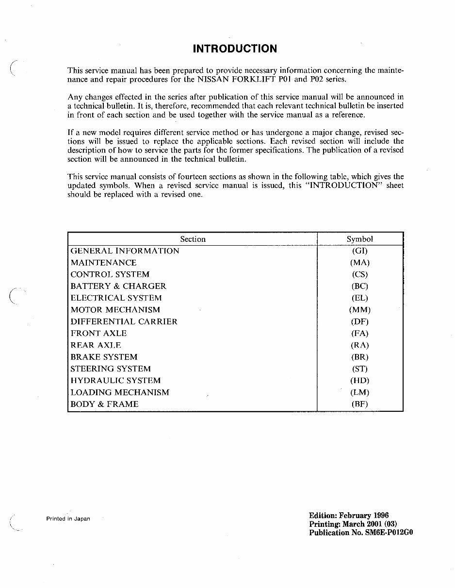
This service manual has been prepared to provide necessary information concerning the mainte-
nance and repair procedures for the NISSAN FORKLIFT POI and P02 series.
Any changes effected in the series after publication of this service manual will be announced in
a technical bulletin. It is, therefore, recommended that each relevant technical bulletin be inserted
in front of each section and be used together with the service manual as a reference.
If a new model requires different service method or has undergone a major change, revised sec-
tions will be issued to replace the applicable sections. Each revised section will include the
description of how to service the parts for the former specifications. The publication of a revised
section will be announced in the technical bulletin.
This service manual consists of fourteen sections as shown in the following table, which gives the
updated symbols. When a revised service manual is issued, this "INTRODUCTION" sheet
should be replaced with a revised one.
Section Symbol
GENERAL INFORMATION (GI)
MAINTENANCE (MA)
CONTROL SYSTEM (CS)
BATTERY & CHARGER (Be)
ELECTRICAL SYSTEM (EL)
MOTOR MECHANISM (MM)
DIFFERENTIAL CARRIER (DF)
FRONT AXLE (FA)
REAR AXLE (RA)
BRAKE SYSTEM (BR)
STEERING SYSTEM (ST)
HYDRAULIC SYSTEM (HD)
LOADING MECHANISM (LM)
BODY & FRAME (BF)
Printed in Japan
Edition: February 1996
Printing: March 2001 (03)
Publication No. SM6E.POI2GO

FOREWORD
© 2010 NFE B.V. Printed in The Netherlands
This manual contains maintenance and repair procedures.
In order to assure your safety and the efficient functioning of the lift truck, this manual should be read
thoroughly. It is especially important that the PRECAUTIONS in the GI section be completely
understood before starting any repair task.
All information in this manual is based on the latest product information at the time of publication.
The right is reserved to make changes in specifications and methods at any time without notice.
IMPORTANT SAFETY NOTICE
The proper performance of service is essential for both the safety of the technician and the efficient
functioning of the lift truck.
The service methods in this Service Manual are described in such a manner that the service may be
performed safely and accurately.
Service varies with the procedures used, the skills of the technician and the tools and parts available.
Accordingly, anyone using service procedures, tools or parts which are not specifically recommended
by NISSAN must first be completely satisfied that neither personal safety nor the lift truck's safety will
be jeopardized by the service method selected.
No modifications or alterations to a powered industrial truck, which may affect, for example, capacity,
stability or safety requirements of the truck shall be made without the prior written approval of
NISSAN, its authorized representative, or a successor thereof. Contact an authorized NISSAN
FORKLIFT dealer before making any modification or alteration to your industrial truck that may affect,
for example braking, steering, visibility and the addition of removable attachments. After getting
approval of NISSAN, its authorized representative, or a successor thereof, capacity plate, decals tags
and operation and maintenance handbooks shall also be changed to the appropriate one.
Only in the event that NISSAN is no longer in business and there is no successor in the interest to the
business, the user may arrange for a modification or alteration to a powered industrial truck, provided,
however, that the user shall:
A. Arrange for the modification or alteration to be designed, tested and implemented by an engineer(s)
expert in industrial trucks and their safety;
B. Maintain a permanent record of the design, test(s) and implementation of the modification or
alteration;
C. Approve and make appropriate changes to the capacity plate(s), decals, tags and Instruction
Handbook;
D. Affix a permanent and readily visible label to the truck stating the manner in which the truck has
been modified or altered together with the date of the modification or alteration, and the name and
address of the organization that accomplished the tasks.
(
\
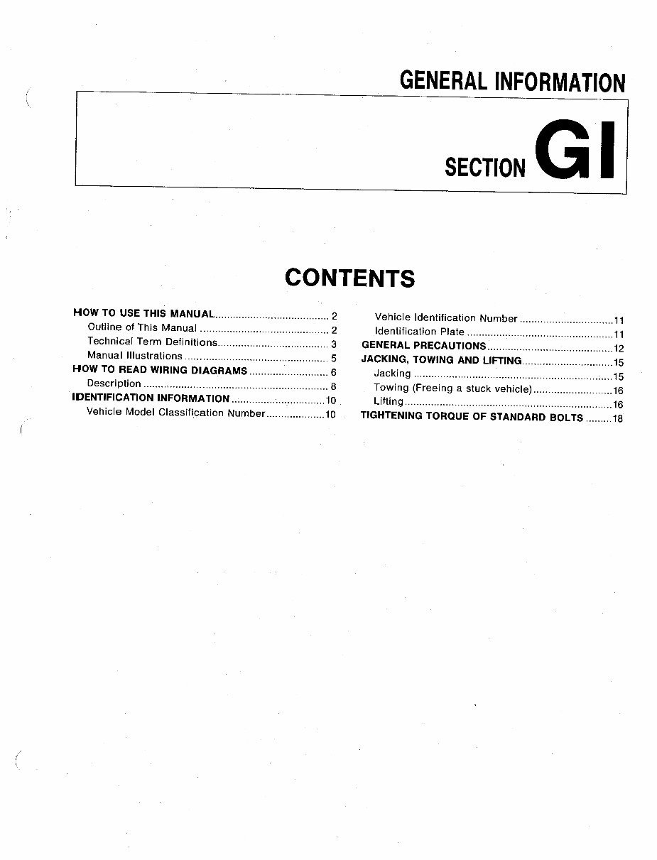
GENERAL INFORMATION
SECTION G I
CONTENTS
HOW TO USE THIS MANUAL 2
Outline of This Manual 2
Technical Term Definitions 3
Manual Illustrations 5
HOW TO READ WIRING DIAGRAMS 6
Description 8
IDENTIFICATION INFORMATION 10
Vehicle Model Classification Number 10
Vehicle Identification Number 11
Identification Plate 11
GENERAL PRECAUTIONS 12
JACKING, TOWING AND L1FTING 15
Jacking 15
Towing (Freeing a stuck vehicle) 16
Lifting 16
TIGHTENING TORQUE OF STANDARD BOLTS 18
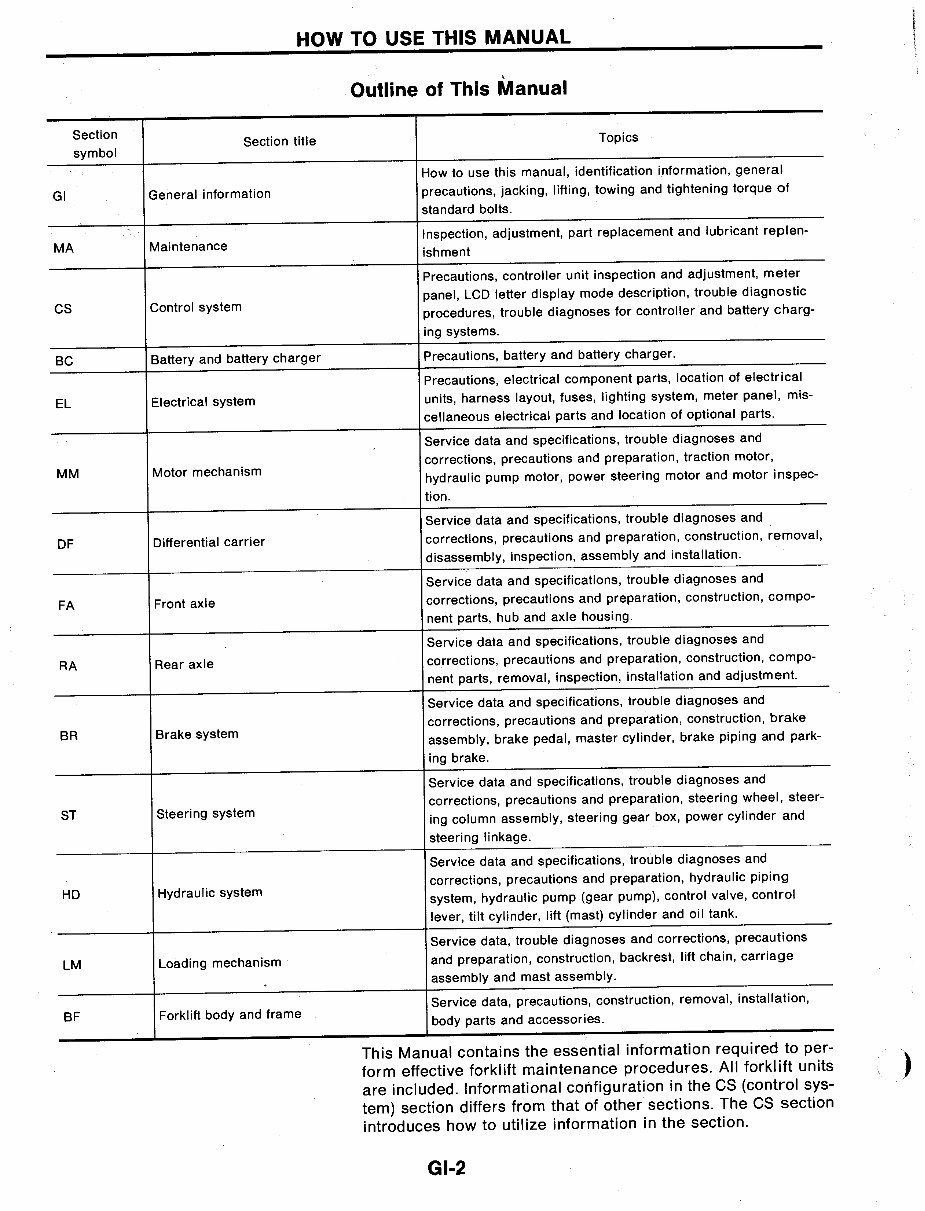
HOW TO USE THIS MANUAL
\
Outline of This Manual
Section
Section title
Topics
symbol
How to use this manual, identification information, general
GI
General information
precautions, jacking, lifting, towing and tightening torque of
standard bolts.
MA
Maintenance
Inspection, adjustment, part replacement and lubricant replen-
ishment
Precautions, controller unit inspection and adjustment, meter
CS
Control system
panel, LCD letter display mode description, trouble diagnostic
procedures, trouble diagnoses for controller and battery charg-
ing systems.
BC
Battery and battery charger
Precautions, battery and battery charger.
Precautions, electrical component parts, location of electrical
EL
Electrical system
units, harness layout, fuses, lighting system, meter panel, mis-
cellaneous electrical parts and location of optional parts.
Service data and specifications, trouble diagnoses and
MM
Motor mechanism
corrections, precautions and preparation, traction motor,
hydraulic pump motor, power steering motor and motor inspec-
tion.
Service data and specifications, trouble diagnoses and
DF
Differential carrier
corrections, precautions and preparation, construction, removal,
disassembly, inspection, assembly and installation.
Service data and specifications, trouble diagnoses and
FA
Front axle
corrections, precautions and preparation, construction, compo-
nent parts, hub and axle housing.
Service data and specifications, trouble diagnoses and
RA Rear axle
corrections, precautions and preparation, construction, compo-
nent parts, removal, inspection, installation and adjustment.
Service data and specifications, trouble diagnoses and
BR
Brake system
corrections, precautions and preparation, construction, brake
assembly, brake pedal, master cylinder, brake piping and park-
ing brake.
Service data and specifications, trouble diagnoses and
ST
Steering system
corrections, precautions and preparation, steering wheel, steer-
ing column assembly, steering gear box, power cylinder and
steering linkage.
Service data and specifications, trouble diagnoses and
HD
Hydraulic system
corrections, precautions and preparation, hydraulic piping
system, hydraulic pump (gear pump), control valve, control
lever, tilt cylinder, lift (mast) cylinder and oil tank.
Service data, trouble diagnoses and corrections, precautions
LM
Loading mechanism
and preparation, construction, backrest, lift chain, carriage
assembly and mast assembly .
.
Service data, precautions, construction, removal, installation,
BF
Forklift body and frame
body parts and accessories.
This Manual contains the essential information required to per-
form effective forklift maintenance procedures. All forklift units
are included. Informational configuration in the CS (control sys-
tem) section differs from that of other sections. The CS section
introduces how to utilize information in the section.
GI-2
)
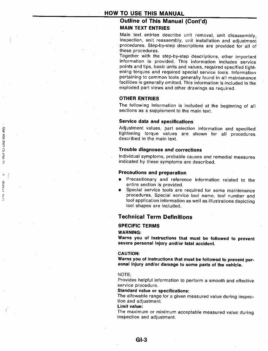
HOW TO USE THIS MANUAL
Outline of This Manual (Cont'd)
MAIN TEXT ENTRIES
Main text entries describe unit removal, unit disassembly,
inspection, unit reassembly, unit installation and adjustment
procedures. Step-by-step descriptions are provided for all of
these procedures.
Together with the step-by-:-step descriptions, other important
information is. provided. This information includes service
points and tips, basic units and values, required specified tight-
ening torques and required special service tools. Information
pertaining to common tools generally found in all maintenance
facilities is generally omitted. This information is included in the
exploded part views and other drawings as required.
OTHER ENTRIES
The following information is included at the beginning of all
sections as a supplement to the main text.
Service data and specifications
Adjustment values, part selection information and specified
tightening torque values are shown for all procedures
described in the main text.
Trouble diagnoses and corrections
Individual symptoms, probable causes and remedial measures
indicated by these symptoms are described.
Precautions and preparation
• Precautionary and reference information related to the
entire section is provided.
• Special service tools are required for some maintenance
procedures. Special service tool name, tool number and
tool application information as well as illustrations depicting
tool shapes are included.
Technical Term Definitions
SPECIFIC TERMS
WARNING:
Warns you of instructions that must be followed to prevent
severe personal injury and/or fatal accident.
CAUTION:
Warns you of instructions that must be followed to prevent per-
sonal injury and/or damage to some parts of the vehicle.
NOTE:
Provides helpful information to perform a smooth and effective
service procedure.
Standard value or specifications:
The allowable range for a given measured value during inspec-
tion and adjustment.
Limit value:
The maximum or minimum acceptable measured value during
inspection and adjustment.
GI-3
HOW TO USE THIS MANUAL
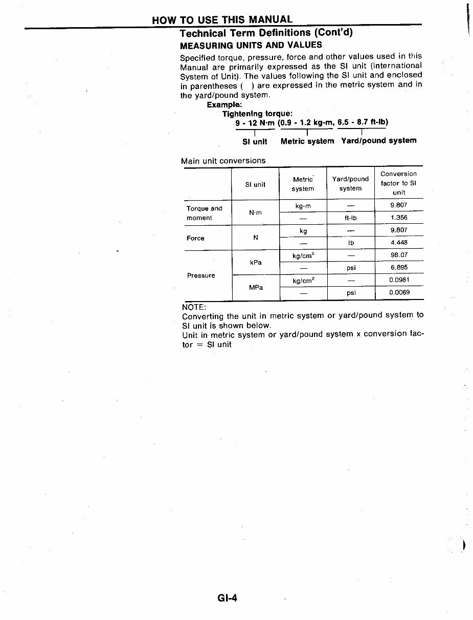
Technical Term Definitions (Cont'd)
MEASURING UNITS AND VALUES
Specified torque, pressure, force and other values used in this
Manual are primarily expressed as the SI unit (International
System of Unit). The values following the SI unit and enclosed
in parentheses ( ) are expressed in the metric system and in
the yard/pound system.
Example:
Tightening torque:
9 - 12 N.m (0.9 - 1.2 kg-m, 6.5 - 8.7 ft-Ib)
I I I
51 unit Metric system Yard/pound system
Main unit conversions
Metric Yard/pound
Conversion
51 unit
factor to 51
system system
unit
Torque and
kg-m - 9.807
N'm
moment
-
ft-Ib 1.356
kg - 9.807
Force N
- Ib 4.448
kg/cm
2
- 98.07
kPa
- psi 6.895
Pressure
kg/cm
2
- 0.0981
MPa
- psi 0.0069
NOTE:
Converting the unit in metric system or yard/pound system to
SI unit is shown below.
Unit in metric system or yard/pound system x conversion fac-
tor = SI unit
GI-4
)
HOW TO USE THIS MANUAL
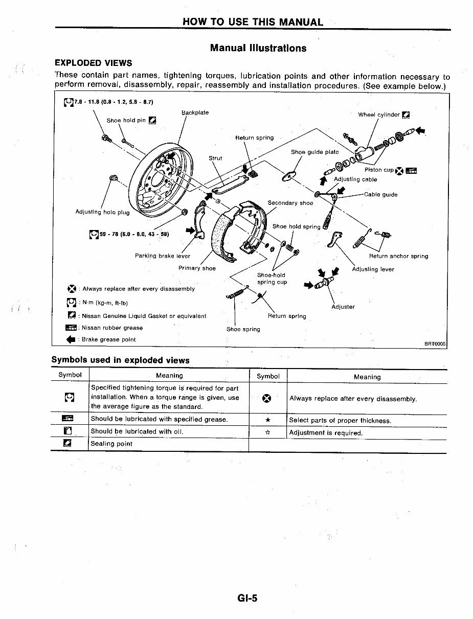
Manual Illustrations
EXPLODED VIEWS
These contain part names, tightening torques, lubrication points and other information necessary to
perform removal, disassembly, repair, reassembly and installation procedures. (See example below.)
Backplate
Primary shoe
~ : Always replace after every disassembly
(OJ : N'm (kg-m, ft-Ib)
~ : Nissan Genuine Liquid Gasket or equivalent
EEi!I: Nissan rubber grease
.. : Brake grease point
Symbols used in exploded views
Shoe spring
BRTOO05
Symbol Meaning Symbol Meaning
Specified tightening torque is required for part
(OJ installation. When a torque range is given, use
~
Always replace after every disassembly.
the average figure as the standard.
EEi!I Should be lubricated with specified grease.
*
Select parts of proper thickness.
f] Should be lubricated with oil.
*
Adjustment is required.
D
Sealing point
GI-5
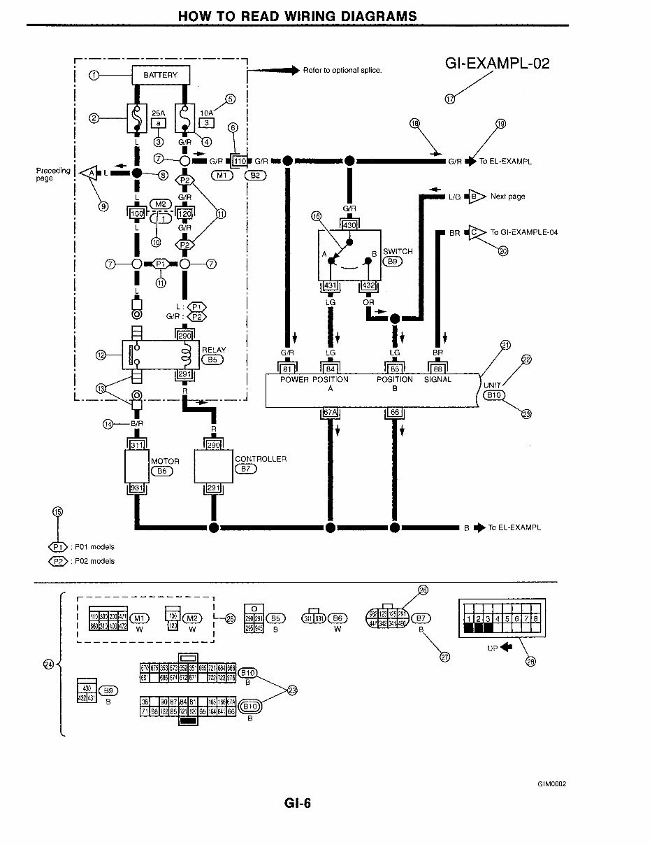
:@H E@ C736 H;C;?9 6;39C3>D
+
KD@J)
o
o
9H o Jc >@'<N8CFB<'*.
o
h
) (" ) DWlh dSYW
&(
o
I@>D8B
h
9 IM@J:?
7%
h
9;'7I3>A=')+
)
CCC (K ("B((0 CC I> BoCFB
@
h
"!' B>
ff+XX[ GG!?;
FEM<H FEI@J@ED
5
H<B8O
**
o
F """"""#' """"
4'FI *
,
2
CEJEH :EDJHEBB<H
7 7%
? ()
1*
f ff JJ f J
B' 9 (Jc<B'<N8CFB
+!!!!!!!!!!!!!!!!!!!!!!!!!"
''R ppo HWXWf hc cdh[cbS_ gd_[UW(
@
@
@
@
(
@
&
@
&
@
& +-
B RR
+
/
F+ ( F*+ acVW_g
74 F*, acVW_g
FfWUWV[bY
dSYW
... ../
Z[_7
o9
c
,18,1+4
,1/1./ 6
>@C***,
9;'.
:@H E@ C736 H;C;?9 6;39C3>D
@[_SYXKV][VSMO
F*+ acVW_g F*, acVW_g
>@C***-
+*8
a
"!'
h5A
,1*
b >9=5@
K :@;
o
+*8
a
"!'
=(:)>I
$Q@%
B
@
,')"
@
B
o7
+o@:[__
B
@
!V
B
+,2* ;
9;'/
You're Reading a Preview
What's Included?
Fast Download Speeds
Online & Offline Access
Access PDF Contents & Bookmarks
Full Search Facility
Print one or all pages of your manual
$50.99
NISSAN Forklift P01 P02 PO1 PO2 series Workshop Service Manual
Viewed 77 Times Today

What's Included?
Fast Download Speeds
Online & Offline Access
Access PDF Contents & Bookmarks
Full Search Facility
Print one or all pages of your manual
$50.99

Secure transaction
What's Included?
Fast Download Speeds
Online & Offline Access
Access PDF Contents & Bookmarks
Full Search Facility
Print one or all pages of your manual
Description
The NISSAN FORKLIFT P01 P02 PO1 PO2 series WORKSHOP SHOP REPAIR SERVICE MANUAL provides comprehensive information on the following:
- GENERAL INFORMATION
- MAINTENANCE
- CONTROL SYSTEM
- BATTERY & CHARGER
- ELECTRICAL SYSTEM
- MOTOR MECHANISM
- DIFFERENTIAL CARRIER
- FRONT AXLE
- REAR AXLE
- BRAKE SYSTEM
- STEERING SYSTEM
- HYDRAULIC SYSTEM
- LOADING MECHANISM
- BODY & FRAME
This manual is useful for both professional mechanics and DIY enthusiasts.


