

Nissan Forklift Electric N01 Series* Factory Service / Repair/ Workshop Manual !
What's Included?
Fast Download Speeds
Online & Offline Access
Access PDF Contents & Bookmarks
Full Search Facility
Print one or all pages of your manual
SERVICE MANUAL &
TECHNICAL BULLETIN
SERVICE MANUAL &
TECHNICAL BULLETIN
MODEL N01 SERIES
INTRODUCTION
This service manual has been prepared to provide necessary information concerning the
maintenance and repair procedures for the NISSAN FORKLIFT NOt series.
Any changes effected in the series after publication of this service manual will be
announced in a technical bUlletin. It is, therefore, recommended that each relevant technical
bulletin be inserted in front of each section and be used together with the service manual
as a reference.
If a new model requires different service method or has undergone a major change,
revised sections will be issued to replace the applicable sections. Each revised section will
include the description of how to service the parts for the former specifications. The pub-
lication of a revised section will be announced in the technical bulletin.
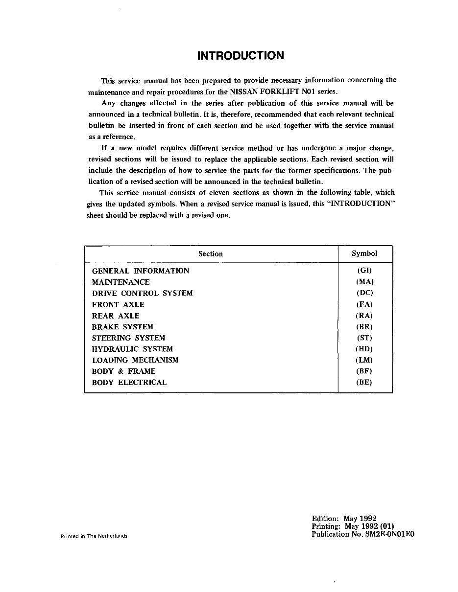
This service manual consists of eleven sections as shown in the following table, which
gives the updated symbols. When a revised service manual is issued, this "INTRODUCTION"
sheet should be replaced with a revised one.
Section Symbol
GENERAL INFORMATION
(GI)
MAINTENANCE
(MA)
DRIVE CONTROL SYSTEM
(DC)
FRONT AXLE (FA)
REAR AXLE (RA)
BRAKE SYSTEM (BR)
STEERING SYSTEM (ST)
HYDRAULIC SYSTEM (HD)
LOADING MECHANISM (LM)
BODY&FRAME(BF)
BODYELECTRICAL(BE)
Printed in The Netherlands
Edition: May 1992
Printing: May 1992 (01)
Publication No. SM2E.ON01EO
CONTROL SYSTEM (CS)

FOREWORD
© 2010 NFE B.V. Printed in The Netherlands
This manual contains maintenance and repair procedures.
In order to assure your safety and the efficient functioning of the lift truck, this manual should be read
thoroughly. It is especially important that the PRECAUTIONS in the GI section be completely
understood before starting any repair task.
All information in this manual is based on the latest product information at the time of publication.
The right is reserved to make changes in specifications and methods at any time without notice.
IMPORTANT SAFETY NOTICE
The proper performance of service is essential for both the safety of the technician and the efficient
functioning of the lift truck.
The service methods in this Service Manual are described in such a manner that the service may be
performed safely and accurately.
Service varies with the procedures used, the skills of the technician and the tools and parts available.
Accordingly, anyone using service procedures, tools or parts which are not specifically recommended
by NISSAN must first be completely satisfied that neither personal safety nor the lift truck's safety will
be jeopardized by the service method selected.
No modifications or alterations to a powered industrial truck, which may affect, for example, capacity,
stability or safety requirements of the truck shall be made without the prior written approval of
NISSAN, its authorized representative, or a successor thereof. Contact an authorized NISSAN
FORKLIFT dealer before making any modification or alteration to your industrial truck that may affect,
for example braking, steering, visibility and the addition of removable attachments. After getting
approval of NISSAN, its authorized representative, or a successor thereof, capacity plate, decals tags
and operation and maintenance handbooks shall also be changed to the appropriate one.
Only in the event that NISSAN is no longer in business and there is no successor in the interest to the
business, the user may arrange for a modification or alteration to a powered industrial truck, provided,
however, that the user shall:
A. Arrange for the modification or alteration to be designed, tested and implemented by an engineer(s)
expert in industrial trucks and their safety;
B. Maintain a permanent record of the design, test(s) and implementation of the modification or
alteration;
C. Approve and make appropriate changes to the capacity plate(s), decals, tags and Instruction
Handbook;
D. Affix a permanent and readily visible label to the truck stating the manner in which the truck has
been modified or altered together with the date of the modification or alteration, and the name and
address of the organization that accomplished the tasks.
GENERAL INFORMATION
SECTION G I
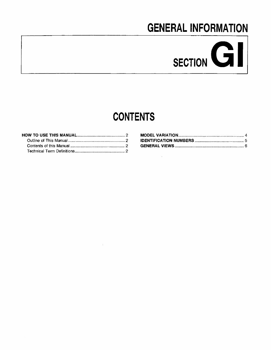
CONTENTS
HOW TO USE THIS MANUAL 2
Outline of This Manual 2
Contents of this Manual 2
Technical Term Definitions 2
MODEL VARIATION 4
IDENTIFICATION NUMBERS 5
GENERAL VIEWS 6
HOW TO USE THIS MANUAL
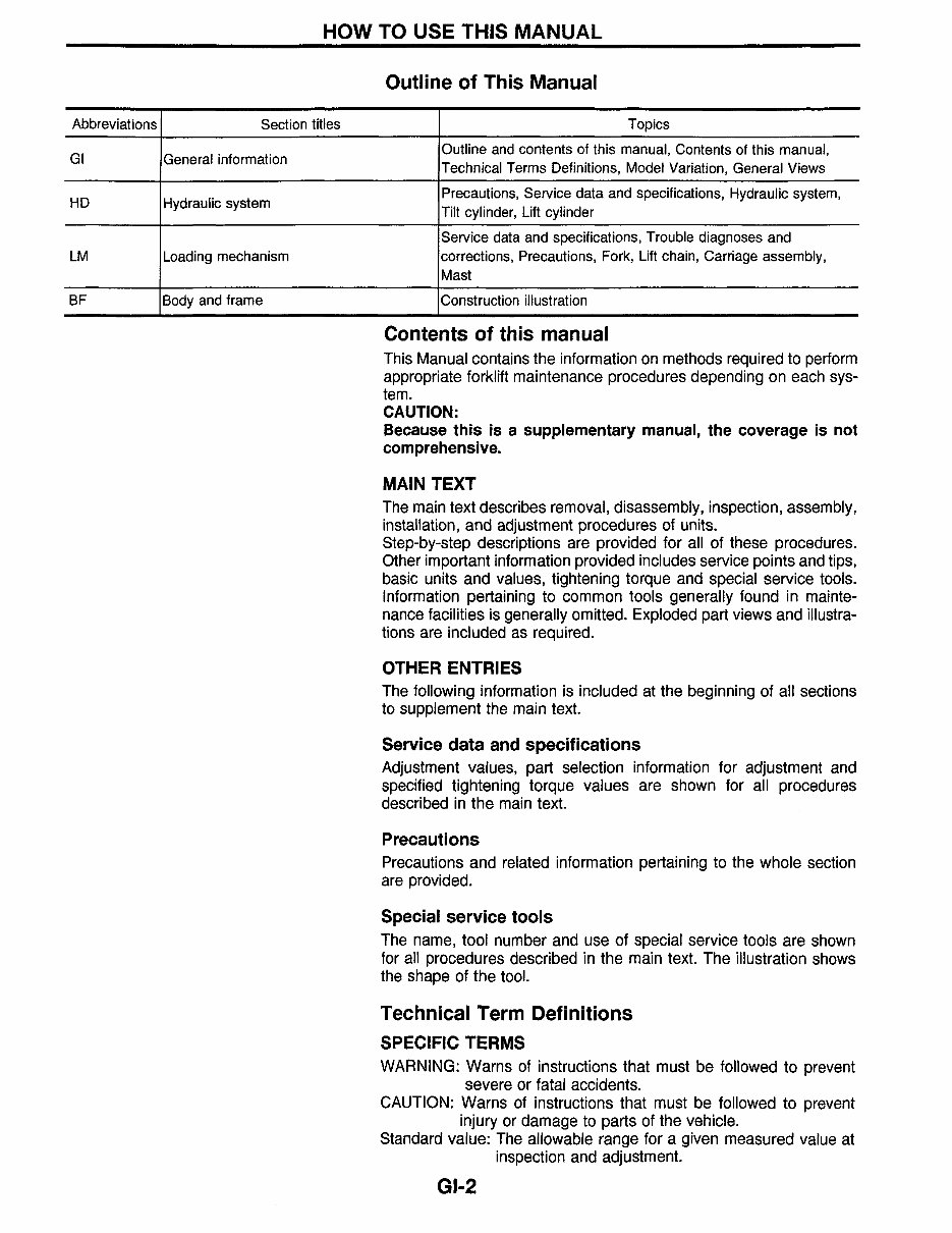
Outline of This Manual
Abbreviations Section titles Topics
GI General information
Outline and contents of this manual, Contents of this manual,
Technical Terms Definitions, Model Variation, General Views
HD Hydraulic system
Precautions, Service data and specifications, Hydraulic system,
Tilt cylinder, Lift cylinder
Service data and specifications, Trouble diagnoses and
LM Loading mechanism corrections, Precautions, Fork, Lift chain, Carriage assembly,
Mast
BF Body and frame Construction illustration
Contents of this manual
This Manual contains the information on methods required to perform
appropriate forklift maintenance procedures depending on each sys-
tem.
CAUTION:
Because this is a supplementary manual, the coverage is not
comprehensive.
MAIN TEXT
The main text describes removal, disassembly, inspection, assembly,
installation, and adjustment procedures of units.
Step-by-step descriptions are provided for all of these procedures.
Other important information provided includes service points and tips,
basic units and values, tightening torque and special service tools.
Information pertaining to common tools generally found in mainte-
nance facilities is generally omitted. Exploded part views and illustra-
tions are included as required.
OTHER ENTRIES
The following information is included at the beginning of all sections
to supplement the main text.
Service data and specifications
Adjustment values, part selection information for adjustment and
specified tightening torque values are shown for all procedures
described in the main text.
Precautions
Precautions and related information pertaining to the whole section
are provided.
Special service tools
The name, tool number and use of special service tools are shown
for all procedures described in the main text. The illustration shows
the shape of the tool.
Technical Term Definitions
SPECIFIC TERMS
WARNING: Warns of instructions that must be followed to prevent
severe or fatal accidents.
CAUTION: Warns of instructions that must be followed to prevent
injury or damage to parts of the vehicle.
Standard value: The allowable range for a given measured value at
inspection and adjustment.
GI-2
HOW TO USE THIS MANUAL
Technical Term Definitions (Cont'd)
Limit value: The maximum or minimum acceptable measured value
at inspection or adjustment.
POSITION AND DIRECTION
The description of direction (front, back, left, right, up and down) in
this manual is based on the position of a driver sitting in the driver's
seat.
MEASURING UNITS AND VALUES
The UNITS given in this manual are primarily expressed as the SI
UNIT (International System of Unit), and alternatively expressed in
the metric system and in the yard/pound system.
"Example"
Tightening torque:
59 - 78 Nom (6.0 - 8.0 kg-m, 43 - 58 ft-Ib)
GI.3
MODEL VARIATION
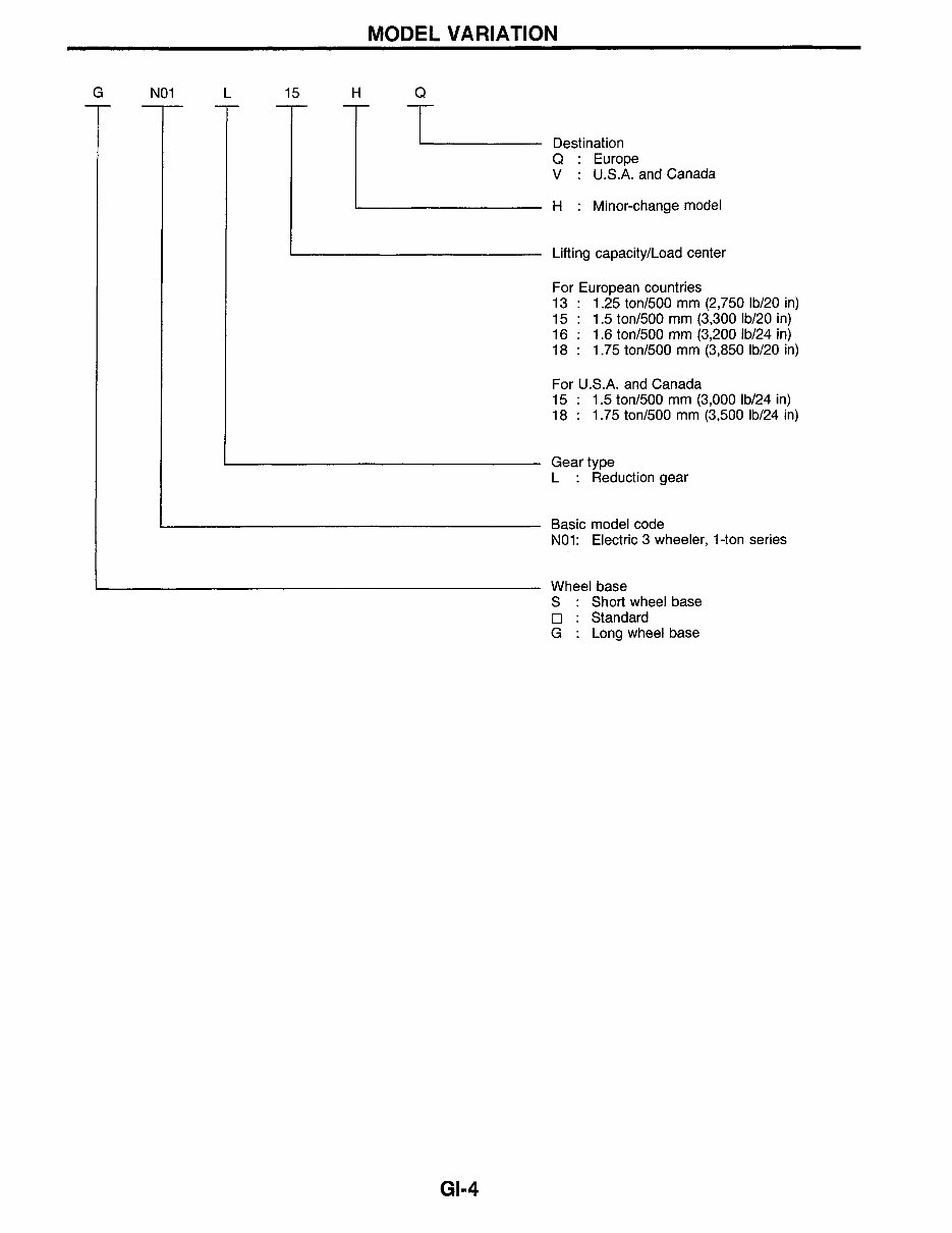
G N01 L 15 H
Q
T
GI.4
Destination
Q Europe
V U.S.A. and Canada
H Minor-change model
Lifting capacity/Load center
For European countries
13 1.25 ton/500 mm (2,750 Ib/20 in)
15 1.5 ton/500 mm (3,300 Ib/20 in)
16 : 1.6 ton/500 mm (3,200 Ib/24 in)
18 : 1.75 ton/500 mm (3,850 Ib/20 in)
For U.S.A. and Canada
15 : 1.5 ton/500 mm (3,000 Ib/24 in)
18 : 1.75 ton/500 mm (3,500 Ib/24 in)
Gear type
L : Reduction gear
Basic model code
N01: Electric 3 wheeler, Hon series
Wheel base
S Short wheel base
D : Standard
G : Long wheel base
IDENTIFICAIOiN" NUMBERS
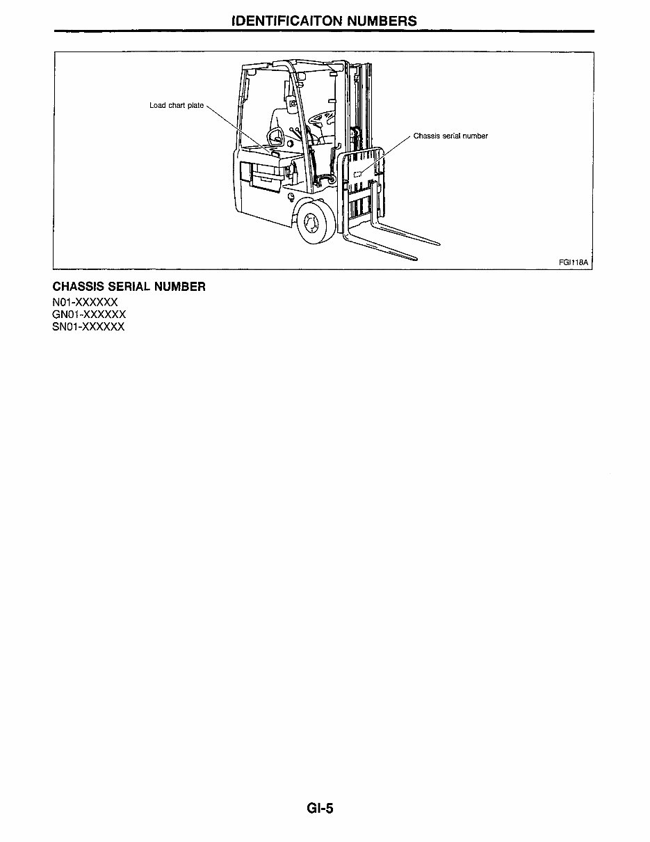
CHASSIS SERIAL NUMBER
N01-XXXXXX
GN01-XXXXXX
SN01-XXXXXX
GI.5
FGJl18A
",t
..5
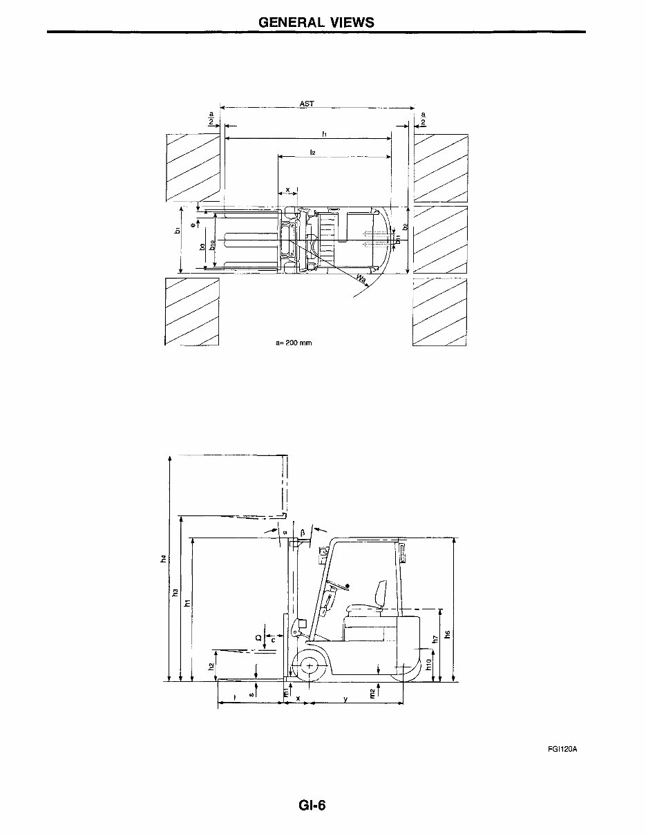
GENERAL VIEWS
~
II
II
J
I J
GI.6
o
.E
co
.... &.
&.
FGI120A
GENERAL VIEWS
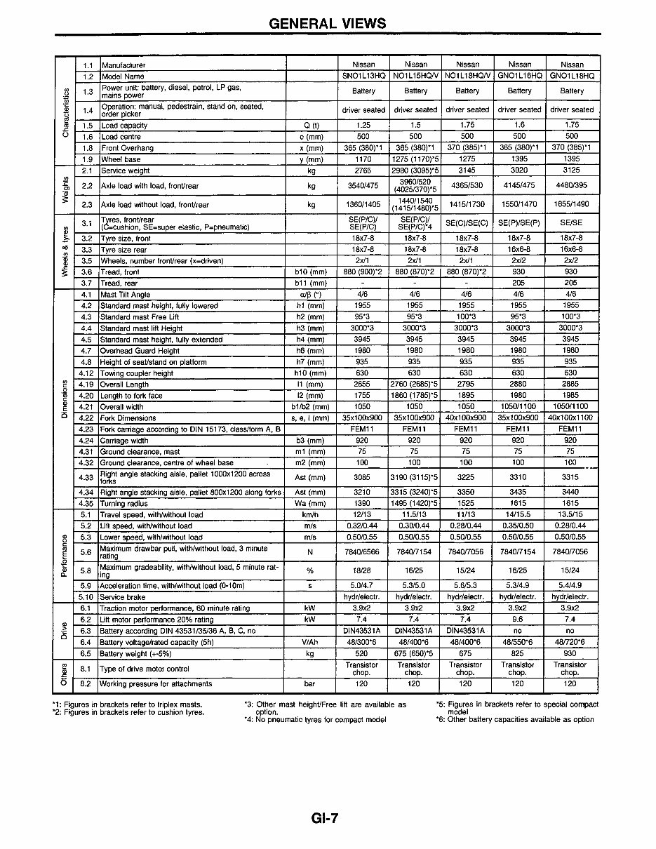
1.1 Manufacturer Nissan Nissan Nissan Nissan Nissan
1.2 Model Name SN01L13HQ N01L15HQN N01L18HQN GN01L16HQ GN01L18HQ
en
1.3
Power unit: battery, diesel, petrol, LP gas,
Battery Battery Battery Battery Battery
0
mains power
~
"f6
1.4
Operation: manual, pedestrain, stand on, seated,
driver seated driver seated driver seated driver seated driver seated
0 order picker
~ 1.5 Load capacity Q(t) 1.25 1.5 1.75 1.6 1.75
.s::.
<..J
1.6 Load centre c(mm) 500 500 500 500 500
1.8 Front Overhang x (mm) 365 (380)*1 365 (380)*1 370 (385)*1 365 (380)*1 370 (385)*1
1.9 Wheel base y(mm) 1170 1275 (1170)*5 1275 1395 1395
2.1 Service weight kg 2765 2980 (3095)*5 3145 3020 3125
en
3960/520
1:
2.2 Axle load with load, fronVrear kg 3540/475 4365/530 4145/475 4480/395
Cl
(4025/370)*5
~
2.3 Axle load without load, fronVrear kg 1360/1405
1440/1540
1415/1730 1550/1470 1655/1490
(1415/1480)*5
3.1
TteS, fronVrear SE(P/C)/ SE(P/C)/
SE(C)/SE(C) SE(P)/SE(P) SEISE
en ( =cushion, SE=super elastic, P=pneumatic) SE(P/C) SE(P/C)*4
~
3.2 Tyre size, front 18x7-8 18x7-8 18x7-8 18x7-8 18x7-8
z:.
ell
3.3 Tyre size rear 18x7-8 18x7-8 18x7-8 16x6-8 16x6-8
en
Qi
3.5 Wheels, number fronVrear (x=driven) 2x11 2x11 2x11 2x12 2x12
Q)
.s::.
3.6 Tread, front bl0 (mm) 880 (900)*2 880 (870)*2 880 (870)*2 930 930
:s:
3.7 Tread, rear bll (mm) - - - 205 205
4.1 Mast Tilt Angle a1~ (0) 4/6 4/6 4/6 4/6 4/6
4.2 Standard mast height, fully lowered hl (mm) 1955 1955 1955 1955 1955
4.3 Standard mast Free Lift h2 (mm) 95*3 95*3 100*3 95*3 100*3
4.4 Standard mast lift Height h3 (mm) 3000*3 3000*3 3000*3 3000*3 3000*3
4.5 Standard mast height, fully extended h4 (mm) 3945 3945 3945 3945 3945
4.7 Overhead Guard Height h6 (mm) 1980 1980 1980 1980 1980
4.8 Height of seaVstand on platform h7 (mm) 935 935 935 935 935
4.12 Towing coupler height hl0 (mm) 630 630 630 630 630
en
4.19 Overall Length 11 (mm) 2655 2760 (2685)*5 2795 2880 2885
"
0
'iii
4.20 Length to fork face 12 (mm) 1755 1860 (1785)*5 1895 1980 1985
"
Q)
4.21 Overall width bl/b2 (mm) 1050 1050 1050 1050/1100 1050/1100
E
is
4.22 Fork Dimensions s, e,l (mm) 35xl00x900 35xl00x900 40xl00x900 35xl00x900 40xl00xll00
4.23 Fork carriage according to DIN 15173, class/form A, B FEMll FEMll FEMll FEM11 FEMll
4.24 Carriage width b3 (mm) 920 920 920 920 920
4.31 Ground clearance, mast ml (mm) 75 75 75 75 75
4.32 Ground clearance, centre of wheel base m2 (mm) 100 100 100 100 100
Right angle stacking aisle, pallet 1000x1200 across
--
4.33
forks
Ast(mm) 3085 3190 (3115)*5 3225 3310 3315
4.34 Right angle stacking aisle, pallet 800x1200 along forks Ast(mm) 3210 3315 (3240)*5 3350 3435 3440
4.35 Turning radius Wa(mm) 1390 1495 (1420)*5 1525 1615 1615
5.1 Travel speed, with/without load km/h 12/13 11.5/13 11/13 14/15.5 13.5/15
5.2 Lift speed, with/without load m/s 0.32/0.44 0.30/0.44 0.28/0.44 0.35/0.50 0.28/0.44
Q)
5.3 Lower speed, with/without load m/s 0.50/0.55 0.50/0.55 0.50/0.55 0.50/0.55 0.50/0.55
0
" Maximum drawbar pull, with/without load, 3 minute nl
5.6 N 7840/6566 7840/7154 784017056 784017154 784017056
E
rating
0
't:
~aximum gradeability, with/without load, 5 minute rat-
Q)
5.8 % 18/28 16/25 15/24 16/25 15/24
c.. mg
5.9 Acceleration time, with/without load (0-10m) s 5.0/4.7 5.3/5.0 5.6/5.3 5.3/4.9 5.4/4.9
5.10 Service brake hydr/electr. hydr/electr. hydr/electr. hydr/electr. hydr/electr.
6.1 Traction motor performance, 60 minute rating kW 3.9x2 3.9x2 3.9x2 3.9x2 3.9x2
Q)
6.2 Lift motor performance 20% rating kW 7.4 7.4 7.4 9.6 7.4
>
6.3 Battery according DIN 43531/35/36 A, B, C, no DIN43531A DIN43531A DIN43531A no no
;5
6.4 Battery voltage/rated capacity (5h) V/Ah 48/300*6 48/400*6 48/400*6 48/550*6 481720*6
6.5 Battery weight (+-5%) kg 520 675 (650)*5 675 825 930
f!1
8.1 Type of drive motor control
Transistor Transistor Transistor Transistor Transistor
Q)
chop. chop. chop. chop. chop .
.s::.
0 8.2 Working pressure for attachments bar 120 120 120 120 120
*1: Figures in brackets refer to triplex masts.
*2: Figures in brackets refer to cushion tyres.
*3: Other mast heighVFree lift are available as
option.
*4: No pneumatic tyres for compact model
GI-7
*5: Figures in brackets refer to special compact
model
*6: Other battery capacities available as option
You're Reading a Preview
What's Included?
Fast Download Speeds
Online & Offline Access
Access PDF Contents & Bookmarks
Full Search Facility
Print one or all pages of your manual
$40.99
Viewed 20 Times Today


Secure transaction
What's Included?
Fast Download Speeds
Online & Offline Access
Access PDF Contents & Bookmarks
Full Search Facility
Print one or all pages of your manual
$40.99
This factory service, repair, and workshop manual provides maintenance and repair procedures for the Nissan Forklift Electric N01 Series. It offers step-by-step instructions, detailed exploded pictures, and diagrams for maintaining, servicing, diagnosing, and repairing the forklift. The manual covers a wide range of repair procedures, including:
- Introduction
- Foreword
- General Information
- Maintenance / Service
- Control System
- Micropack 05/9209/96
- SC2000 09/9604/02
- SEM 05/0209/05
- Front Axle
- Rear Axle
- Brake System
- Steering System
- Hydraulic System
- Loading Mechanism
- Body and Frame
- Body Electric System
The manual is available for instant access without any shipping costs or waiting for physical delivery. It is compatible with all versions of Windows and Mac, and the language used is English. The file format is PDF, and it requires Adobe Reader and Win to access. Upon payment completion, the manual can be accessed immediately, and all pages are printable.


