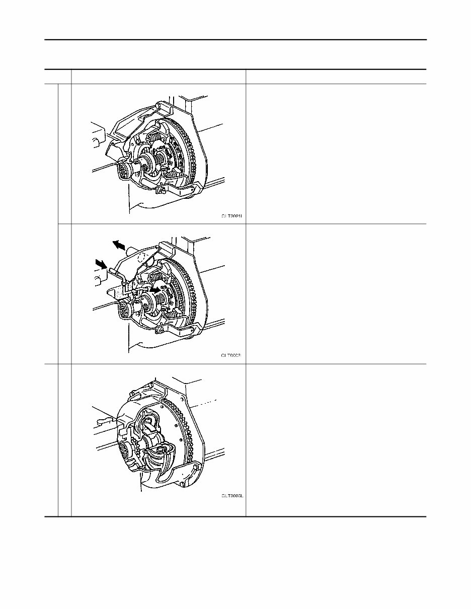
CL-2 1. TYPES AND FEATURES OF POWER TRANSMISSION SYSTEMS Type Construction Features ・This is the most popular structure. Half-clutch operation makes it possible to perform delicate cargo handling work. Thus, it is liked by veteran operators who dislike torque converter vehicles. And since power transmission loss is minimal and output can be used effectively, fuel consumption is reduced. ・ Depending on the type of cargo handling work, the clutch disc life may be shortened and maintenance costs can be high under demanding half-clutch operation. Operability is inferior to that of models with an automatic transmission, and experience and skill are required. ・The operation feel and fuel economy are the same as a dry-clutch-equipped vehicle, but the clutch disc life is much longer than that of a dry type, even with frequent half-clutch operation. ・ In vehicles that are operated for long hours and under harsh conditions, vehicles equipped with attachments such as roll clamps that require frequent half-clutch operations, and vehicles equipped with hinged forks that require traction, this type has a longer clutch life than that of a dry type. ・ Operation is simple, which minimizes operator fatigue and improves work efficiency. (Efficiency is about 10% better than that of models with manual transmission, depending on the work.) ・ Hydraulically operated wet clutch is built into the transmission, so the clutch life is lengthened and it provides the same advantages as that of the aforementioned models with wet clutch (manual transmission). ・ Since power transmission loss occurs, fuel economy is about 10% less per volume of work when compared to models with manual transmission. (On a per-hour basis, it is about 20% inferior, but the volume of work increases about 10%. Of course, these percentages will vary according to the nature of the work and should be considered as general standards only.) CLT0001L CLT0002L CLT0003L TYPES AND FEATURES OF POWER TRANSMISSION SYSTEMS Dry clutch (Manual transmission) Torque converter (Automatic transmission) Wet clutch
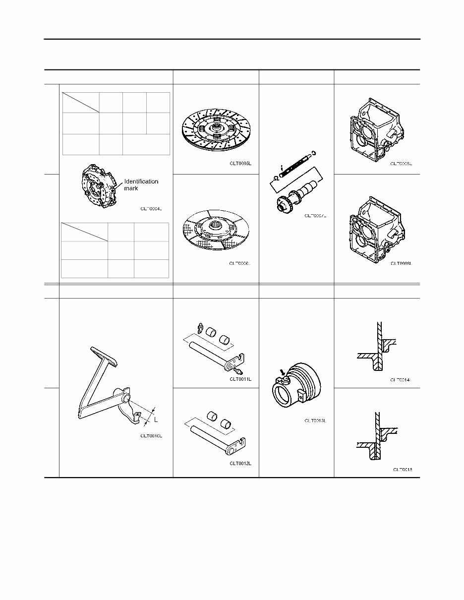
CL-3 2. MAIN DIFFERENCES BETWEEN DRY AND WET CLUTCHES Clutch cover assembly Clutch disc Input shaft Clutch housing Clutch pedal Clutch shaft Clutch bearing E/G packing L = 45 mm (dry) L = 40.5 mm (wet) Grease type With grease nipple Without grease nipple No Yes Engine Items K15 K21 2.5L-4C K25 3.3L-4C Identification mark FJ10 FJ20 FK00 Spring 8 Color- less 12 Colorless CLT0004L Engine Items 2.5L-4C K21 3.3L-4C K25 Identification mark FJ50 FJ51 Spring 10 Brown 12 Brown CLT0005L CLT0007L CLT0008L CLT0006L CLT0009L CLT0010L CLT0011L CLT0013L CLT0014L CLT0012L CLT0015L MAIN DIFFERENCES BETWEEN DRY AND WET CLUTCHES Dry Wet Wet Dry
CL-4 3. MECHANISMS AND FUNCTIONS OF CLUTCHES Dry clutch For the purpose of replacing the clutch disc, a dry clutch has an opening on the upper housing surface. By separating the input shaft and input gear and sliding the spline to the transmission, the clutch disc can easily be replaced. CAUTION • The pressure plate size is common for all vehicle models. Only the number of pressure springs used is different. Wet clutch A wet clutch is sealed with a cover because of its mechanism in which the clutch disc is cooled by the return oil of the clutch booster. The cooled oil is returned to the operating oil tank using the turning force of the flywheel. CAUTION • HDS-3-10W oil is used for diesel engine, and this also serves as lubricant. Do not confuse them when filling. • The pressure plate size is common for all vehicle models. Only the number of pressure springs used is different. 1. Clutch disc 2. Clutch cover assembly 3. Input shaft 4. Release bearing sleeve 5. Release bearing 6. Clutch shifter shaft 7. Front cover CLT0016LÅ@WÅ@ MECHANISMS AND FUNCTIONS OF CLUTCHES
CL-5 4. CLUTCH (1) For Dry Clutch With a dry clutch, a pin is used to connect the direct clutch pedal and push rod of the clutch master cylinder. Clutch operating cylinder absorbs the positional change that occurs in the pressure plate release lever due to clutch disc wear. If the pedal is adjusted at the beginning, it can be used without adjustment. 1. Bracket 2. Clutch pedal 3. Reservoir tank 4. Clutch master cylinder 5. Clutch operating cylinder 6. Stopper bolt CLT0017L CLUTCH
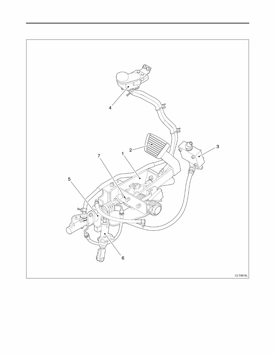
CL-6 (2) For Wet Clutch With a wet clutch, a hydraulic booster is attached to the back of the clutch pedal. Clutch operating cylinder absorbs the positional change that occurs in the pressure plate release lever due to clutch disc wear. If the pedal is adjusted at the beginning, it can be used without adjustment. 1. Bracket 2. Clutch pedal 3. Flow divider 4. Reservoir tank 5. Hydraulic booster 6. Clutch operating cylinder 7. Stopper bolt CLT0018L CLUTCH
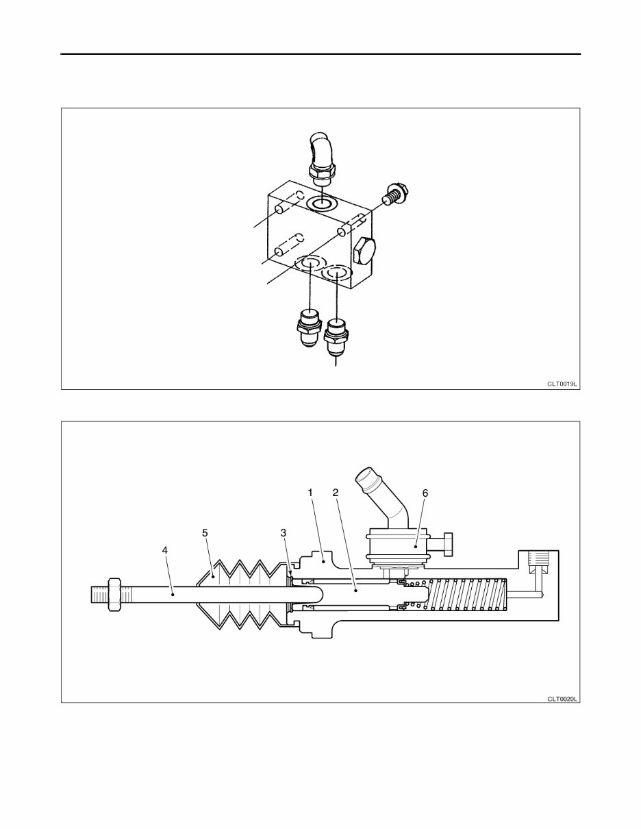
CL-7 (3) Components Flow divider (wet clutch) Clutch master cylinder (dry clutch) 1. Body 2. Piston assembly 3. Snap ring 4. Push rod 5. Boot 6. Filler union CLT0019L CLT0020LÅ@U CLUTCH
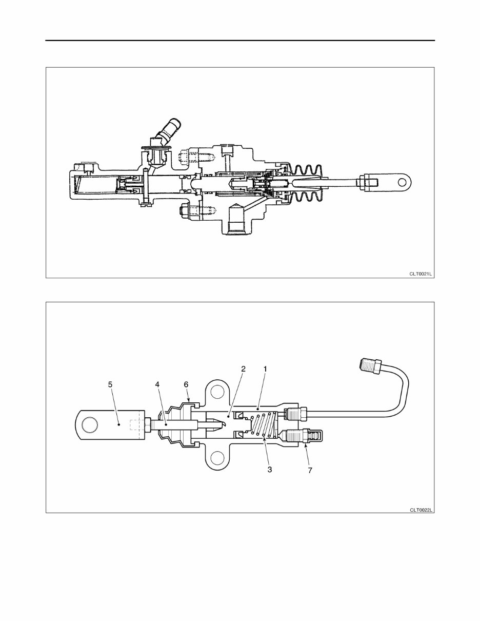
CL-8 Hydraulic booster (wet clutch) Clutch operating cylinder 1. Body 2. Piston assembly 3. Spring 4. Push rod 5. Yoke 6. Boot 7. Air bleeder valve CLT0021LÅ@U CLT0022LÅ@U CLUTCH
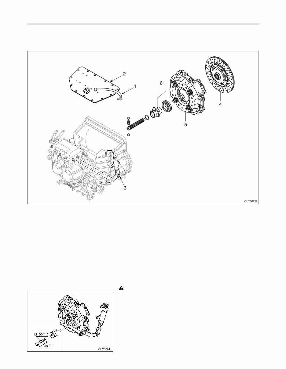
CL-9 5. CLUTCH UNIT (1) Component Parts Location Order of disassembly (2) Disassembly Manual transmission input shaft is a type that can be split with the input gear. Because of this structure, components such as the clutch cover, clutch disc, and release bearing can be removed and installed while the transmission assembly is installed to the chassis. To remove the forks and clutch shaft, however, the engine and transmission assembly must be removed from the chassis. CAUTION • When they are installed to the chassis, there is insufficient space to remove the clutch shaft. Disassembly • Press down on the clutch pedal and tighten 2 bolts (NFF1145- 10050, for removing and installing pressure plate) via washer (NF92301-02700) to put the pressure spring in a compressed state. 1. Hose (wet type only) 2. Clutch cover 3. Clutch operating cylinder pin 4. Clutch disc assembly 5. Clutch cover assembly 6. Release bearing, hub CLT0023LÅ@V CLT0024L CLUTCH UNIT
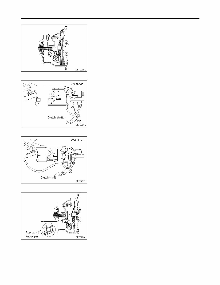
CL-10 • Feed the input shaft into the transmission side. The input shaft will initially be stiff because it is oriented by a steel ball. • Loosen the operating cylinder bleeder valve to release the oil pressure, and then remove the pin that is linked to the clutch shaft. Next, raise the clutch shifter shaft without interfering with the operating cylinder rod clevis. • Place the flywheel knock pin in the position shown in the figure when removing clutch disc assembly and clutch cover assembly. • To replace the input shaft, first remove the engine and transmission assembly. CLT0025L CLT0026L CLT0027L CLT0028L CLUTCH UNIT
Get your hands on the Nissan Forklift Internal Combustion L01, L02 Series Service Repair Manual for comprehensive technical service and repair guidance. This manual is suitable for both professional mechanics and DIY enthusiasts. It is available in PDF format, compatible with all Windows and Mac operating systems. The manual includes easy-to-read text sections, high-quality diagrams, and step-by-step instructions for maintenance, service, and repair. It covers a wide range of topics including engine service, transmission, steering, brake system, hydraulic system, fuel and exhaust system, and more.
The manual also includes additional service manuals for Engine 2.5 / 3.3 Diesel and Engine Gas /LPG K15 / K21 / K25, providing in-depth coverage of engine mechanisms, fuel systems, cooling systems, electric systems, and more. With instant access upon purchase, you can save on shipping and start your repairs without delay. Don't miss out on this valuable resource for maintaining and repairing your Nissan forklift.
Recently Viewed
5,521,897Happy Clients
2,594,462eManuals
1,120,453Trusted Sellers
15Years in Business
Price:
Actual Price:
Nissan Forklift Internal Combustion L01, L02 Series Service Repair Manual INSTANT