

COOLING SYSTEM
COOLING SYSTEM
-p Engine-
(CO)
CONTENTS
SERVICE DATA AND SPECiFiCATIONS CO-2
TROUBLE DIAGNOSES AND CORRECTIONS CO-2
COOLING SySTEM CO-4
WATER PUMP CO-4
THERMOSTAT CO-4
RADIATOR CO-5
Service Data and Specifications -
Trouble Diagnoses and Corrections- COOLING SYSTEM
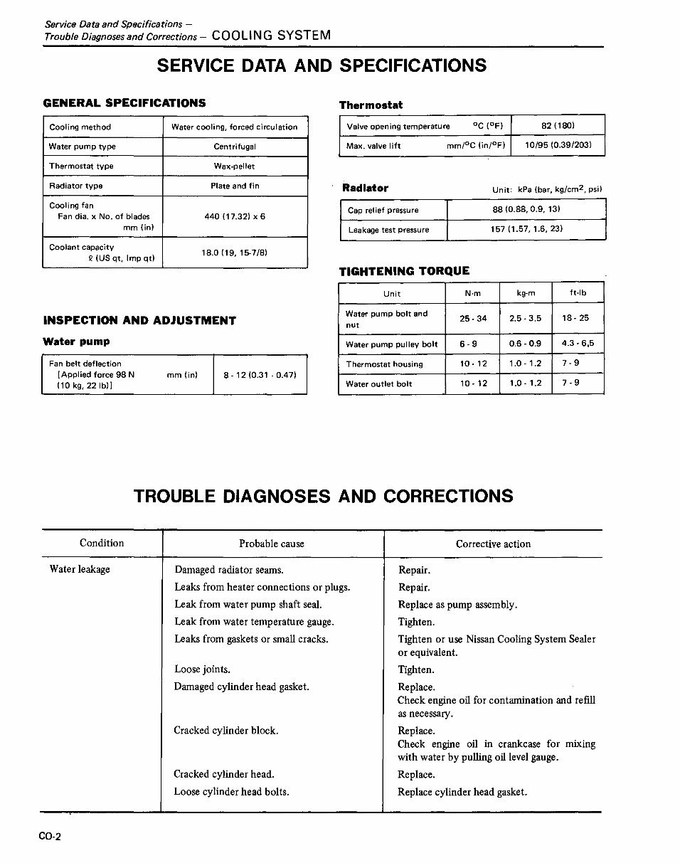
SERVICE DATA AND SPECIFICATIONS
Valve opening temperature
0C (OF) 82 (180)
Max. valve lift
mm/oC (in/oF) 10/95 (0.39/203)
GENERAL SPECIFICATIONS
Cooling method Water cooling, forced circulation
Water pump type Centrifugal
Thermostat type Wax-pellet
Radiator type Plate and fin
Cooling fan
Fan dia. x No. of blades 440 (17.32) x 6
mm (in)
Coolant capacity
18.0 (19,15-7/8)
Q (US qt, Imp qtl
Thermostat
Radiator
Cap relief pressure
Leakage test pressure
TIGHTENING TORQUE
Unit: kPa (bar, kg/cm
2
, psi)
88 (0.88, 0.9, 13)
157 (1.57, 1.6, 23)
INSPECTION AND ADJUSTMENT
Water pump
Fan belt deflection
[Applied force 98 N
(10 kg, 22 Ib)]
mm (in) 8-12 (0.31 - 0.47)
Unit N'm kg-m ft-Ib
Water pump bolt and
25- 34 2.5 - 3.5 18- 25
nut
Water pump pulley bolt 6-9 0.6-0.9 4.3 - 6,5
Thermostat housing 10 - 12 1.0 - 1.2 7-9
Water outlet bolt 10 - 12 1.0 - 1.2 7-9
TROUBLE DIAGNOSES AND CORRECTIONS
Condition
Water leakage
CO-2
Probable cause
Damaged radiator seams.
Leaks from heater connections or plugs.
Leak from water pump shaft seal.
Leak from water temperature gauge.
Leaks from gaskets or small cracks.
Loose joints.
Damaged cylinder head gasket.
Cracked cylinder block.
Cracked cylinder head.
Loose cylinder head bolts.
Corrective action
Repair.
Repair.
Replace as pump assembly.
Tighten.
Tighten or use Nissan Cooling System Sealer
or equivalent.
Tighten.
Replace.
Check engine oil for contamination and refill
as necessary.
Replace.
Check engine oil in crankcase for mixing
with water by pulling oil level gauge.
Replace.
Replace cylinder head gasket.
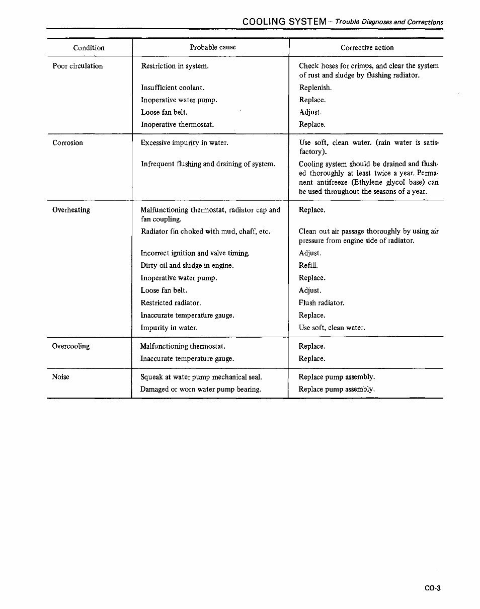
COOLING SYSTEM- Trouble Diagnoses and Corrections
Condition Probable cause Corrective action
Poor circulation Restriction in system. Check hoses for crimps, and clear the system
of rust and sludge by flushing radiator.
Insufficient coolant. Replenish.
Inoperative water pump. Replace.
Loose fan belt. Adjust.
Inoperative thermostat. Replace.
Corrosion Excessive impurity in water. Use soft, clean water. (rain water is satis-
factory).
Infrequent flushing and draining of system. Cooling system should be drained and flush-
ed thoroughly at least twice a year. Perma-
nent antifreeze (Ethylene glycol base) can
be used throughout the seasons of a year.
Overheating Malfunctioning thermostat, radiator cap and Replace.
fan coupling.
Radiator fm choked with mud, chaff, etc. Clean out air passage thoroughly by using air
pressure from engine side of radiator.
Incorrect ignition and valve timing. Adjust.
Dirty oil and sludge in engine. Refill.
Inoperative water pump. Replace.
Loose fan belt. Adjust.
Restricted radiator. Flush radiator.
Inaccurate temperature gauge. Replace.
Impurity in water. Use soft, clean water.
Overcooling Malfunctioning thermostat. Replace.
Inaccurate temperature gauge. Replace.
Noise Squeak at water pump mechanical seal. Replace pump assembly.
Damaged or worn water pump bearing. Replace pump assembly.
CO-3
Cooling System - COOLING SYSTEM
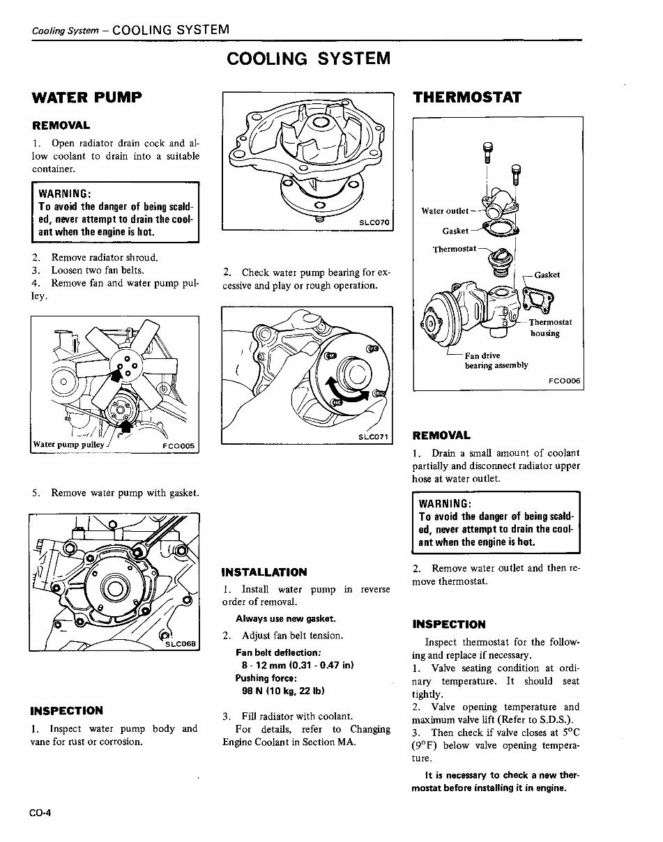
COOLING SYSTEM
WATER PUMP
REMOVAL
1. Open radiator drain cock and al-
low coolant to drain into a suitable
container.
WARNING:
To avoid the danger of being scald-
ed, never attempt to drain the cool.
ant when the engine is hot.
2. Remove radiator shroud.
3. Loosen two fan belts.
4. Remove fan and water pump pul-
ley.
5. Remove water pump with gasket.
INSPECTION
1. Inspect water pump body and
vane for rust or corrosion.
CO-4
2. Check water pump bearing for ex-
cessive and play or rough operation.
SLC071
INSTALLATION
1. Install water pump in reverse
order of removal.
Always use new gasket.
2. Adjust fan belt tension.
Fan belt deflection:
8- 12 mm (0.31 - 0.47 in)
Pushing force:
98 N (10 kg, 22 Ib)
3. Fill radiator with coolant.
For details, refer to Changing
Engine Coolant in Section MA.
THERMOSTAT
~
! ~
w.. ,,:,::::~
Th~mt'~!1 ~._Ga.S.).k:et
~ 0; 'riNJ
Thermostat
housing
Fan drive
bearing assembly
FC0006
REMOVAL
1. Drain a small amount of coolant
partially and disconnect radiator upper
hose at water outlet.
WARNING:
To avoid the danger of being scald.
ed, never attempt to drain the cool-
ant when the engine is hot.
2. Remove water outlet and then re-
move thermostat.
INSPECTION
Inspect thermostat for the follow-
ing and replace if necessary.
1. Valve seating condition at ordi-
nary temperature. It should seat
tightly.
2. Valve opening temperature and
maximum valve lift (Refer to S.D.S.).
3. Then check if valve closes at 5°C
(9°F) below valve opening tempera-
ture.
It is necessary to check a new ther-
mostat before installing it in engine.
COOLING SYSTEM-CoolingSystem
INSTALLATION
1. Position thennostat on thennostat
housing.
2. Install water outlet with new
gasket.
3. Connect radiator upper hose and
fIll radiator with coolant.
4. Run engine for a few minutes, and
check for leaks.
RADIATOR
INSPECTION
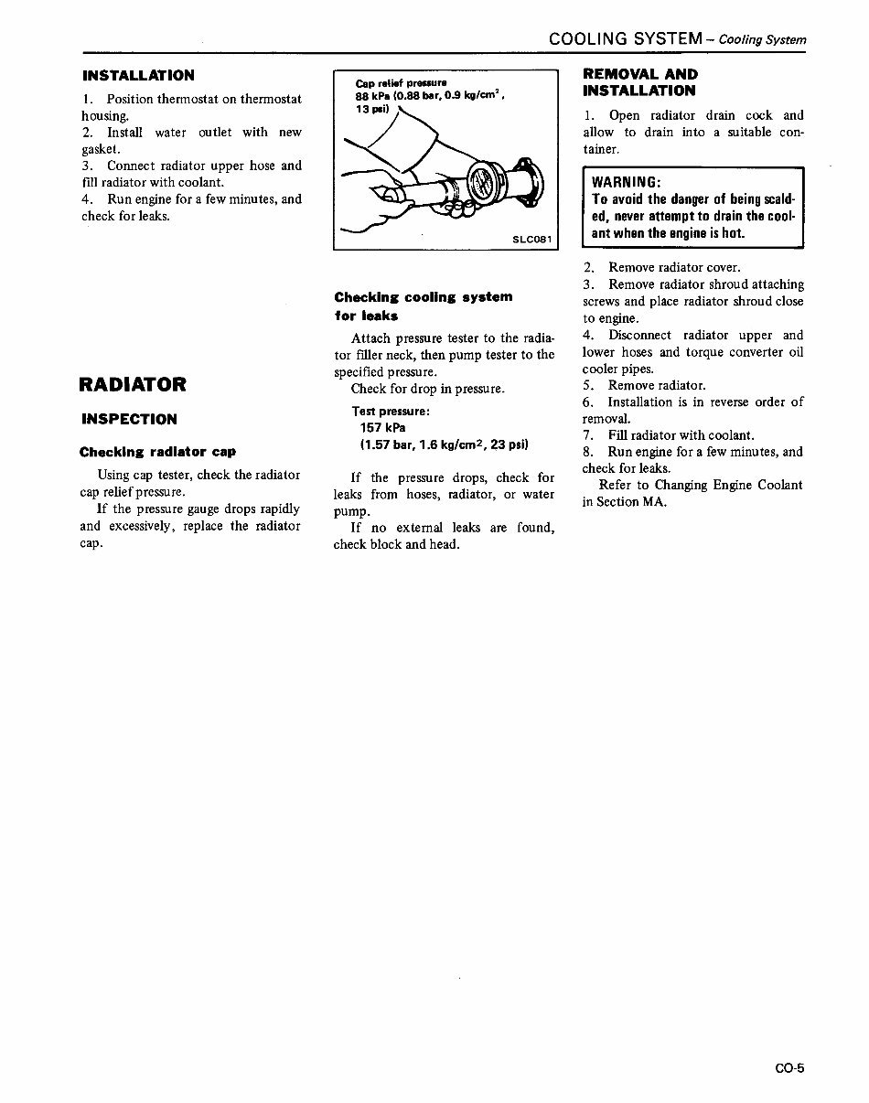
Checking radiator cap
Using cap tester, check the radiator
cap relief pressure.
If the pressure gauge drops rapidly
and excessively, replace the radiator
cap.
SLC081
Checking cooling system
for leaks
Attach pressure tester to the radia-
tor filler neck, then pump tester to the
specifIed pressure.
Check for drop in pressure.
Test pressure:
157 kPa
(1.57 bar, 1.6 kg/cm
2
, ~3 psi)
If the pressure drops, check for
leaks from hoses, radiator, or water
pump.
If no external leaks are found,
check block and head.
REMOVAL AND
INSTALLATION
1. Open radiator drain cock and
allow to drain into a suitable con-
tainer.
WARNING:
To avoid the danger of being scald-
ed, never attempt to drain the cool-
ant when the engine is hot.
2. Remove radiator cover.
3. Remove radiator shroud attaching
screws and place radiator shroud close
to engine.
4. Disconnect radiator upper and
lower hoses and torque converter oil
cooler pipes.
5. Remove radiator.
6. Installation is in reverse order of
removal.
7. Fill radiator with coolant.
8. Run engine for a few minutes, and
check for leaks.
Refer to Changing Engine Coolant
in Section MA.
CO-5
You're Reading a Preview
What's Included?
Fast Download Speeds
Offline Viewing
Access Contents & Bookmarks
Full Search Facility
Print one or all pages of your manual
$37.99
Nissan F03 Series Forklift Internal Combustion Workshop Service Repair Manual
Viewed 16 Times Today

What's Included?
Fast Download Speeds
Offline Viewing
Access Contents & Bookmarks
Full Search Facility
Print one or all pages of your manual
$37.99

Secure transaction
What's Included?
Fast Download Speeds
Offline Viewing
Access Contents & Bookmarks
Full Search Facility
Print one or all pages of your manual
Description
This workshop service repair manual for the Nissan F03 Series Forklift Internal Combustion is an essential resource for both professional mechanics and DIY enthusiasts. It contains high-quality diagrams and detailed instructions covering a wide range of topics, including:
- Introduction
- Cover
- General Information
- Maintenance / Service
- Engine Tune-up
- Engine Mechanical
- Engine Lubrication
- Cooling System
- Engine Fuel
- Governor System
- Engine Electric
- Engine Removal
- Automatic Transmission
- Differential Carrier
- Front Axle
- Rear Axle
- Brake System
- Steering System
- Hydraulic System
- Loading Mechanism
- Engine Control, Fuel and Exhaust System
- Engine Control, Fuel and Exhaust System (F03 series)
- Body and Frame
- Body Electric Systems
This manual is available in PDF format, compatible with all versions of Windows & Mac, as well as various mobile devices. It is a valuable resource for saving on service repair and maintenance costs, and it is instantly accessible upon payment. The language of the manual is English, and it requires Adobe Reader for viewing and printing.


