INTRODUCTION sMost accident happens due to the disregard of basic safety rules or precautions. In order to prevent accidents from happening, the factors responsible for accidents must be avoided beforehand. For this reason, please read this manual and fully understand the precautions for safety and the proper procedures and directions for inspection and maintenance before starting operation. Performing maintenance and repair without adequate knowledge may cause inadvertent accidents. sIt is not possible to cover all the possible cases of accidents in this "WORKSHOP MANUAL". Therefore, attention should be given to precautions other than the ones mentioned in this "WORKSHOP MANUAL". Especially, when repair and maintenance work which are not covered in this "WORKSHOP MANUAL" are carried out, always work under the direction of an instructor who understands the matter.
CONTENTS SAFETY WORK 1 1.Precautions for safe inspection and maintenance work ..............................................1 2. Safety labels ......................................................5 3. Model name and serial numbers .......................9 4. Cautions for maintenance ................................11 5. Tightening torque for bolts ...............................14 1 .GENERAL 16 1-1. Appearance ..................................................16 1-2. Specifications ...............................................17 4 .TYRE 43 4-1. Location, name and tyre size .......................43 4-1-1. Tyre - location and name ...........................43 4-1-2. Tyre size ....................................................43 4-2. Inspection and adjustment ...........................44 4-2-1. Hub nut - inspection ...................................44 4-2-2. Rim and rim bolt - inspection .....................44 4-2-3. Air pressure - inspection ............................45 4-2-4. Tyre - visual inspection and replacement ..45 4-3. Troubleshooting ............................................46 4-3-1. Tyre - troubleshooting ................................46 6. BRAKE 57 6-1. Location and name .......................................57 6-1-1. Foot brake linkage - main part names .......57 6-1-2. Parking brake linkage - main part names ..58 6-2. Disassembly and reassembly.......................59 6-2-1. Wheel brake - removal and installation ......59 6-2-2. Wheel brake - disassembly and reassembly..........................................61 6-3. Inspection and adjustment ...........................62 6-3-1. Brake drum - inspection, repair and replacement ...............................................62 6-3-2. Shoe & lining - inspection and replacement ..62 6-3-3. Adjustor ass'y - inspection and replacement ........................................63 5. STEERING 47 5-1. Location and name .......................................47 5-2. Disassembly and reassembly.......................48 5-2-1. Steering - removal and installation.............48 5-2-2. Steering linkage - disassembly and reassembly..........................................50 5-3. Inspection and adjustment ...........................52 5-3-1. Joint - inspection and replacement ............52 5-3-2. Knob - inspection and replacement ...........52 5-3-3. Steering wheel - inspection and replacement ........................................52 5-3-4. Torque sensor neutral - check and adjustment ..........................................53 5-3-5. Checking by voltage...................................55 5-4. Troubleshooting ............................................56 5-4-1. Steering linkage - troubleshooting .............56 2 .FRONT AXLE (DRIVE) 19 2-1. Location and name .......................................19 2-2. Disassembly and reassembly.......................20 2-2-1. Front axle - removal and installation ..........20 2-2-2. Front axle - disassembly and reassembly..26 2-3. Inspection and adjustment ...........................30 2-3-1. Gears - Inspection and replacement ..........30 2-3-2. Wheel hub and hub bolt - Inspection .........30 2-4. Troubleshooting ............................................31 2-4-1. Front axle - troubleshooting ...................31 3 .REAR AXLE (STEERING) 32 3-1. Location and name .......................................32 3-2. Disassembly and reassembly.......................33 3-2-1. Rear axle - removal and installation...........33 3-2-2. Rear axle - disassembly and reassembly ..35 3-2-3. Rear axle assembly - methods and precautions ................................................37 3-3. Inspection and adjustment ...........................40 3-3-1. Bushing - inspection...................................40 3-3-2. Center arm - inspection..............................40 3-3-3. Tie rod comp. - inspection..........................40 3-3-4. Knuckle - inspection ...................................40 3-3-5. King pin - inspection...................................41 3-3-6. Hub and hub bolt - inspection ....................41 3-3-7. Rear axle comp. - inspection .....................41 3-4. Troubleshooting ............................................42 3-4-1. Rear axle - troubleshooting ........................42
7. HYDRAULIC SYSTEM 68 7-1. Oil piping circuit ............................................68 7c. CONTROL VALVE 77 7c-1. Location and name .....................................77 7c-2. Disassembly and reassembly .....................79 7c-2-1. Control valve - removal and installation.......79 7c-2-2. Inner kit of control valve - replacement........81 7c-3. Inspection and adjustment ..........................82 7c-3-1. Relief pressure - measurement .............82 7c-3-2. Microswitch - adjustment .......................82 7c-4. Troubleshooting ..........................................83 7c-4-1. Control valve - troubleshooting..............83 7d. CYLINDER 84 7d-1. Location and name .....................................84 7d-1-1. Lift cylinder - main part names .................84 7d-1-2. Tilt cylinder - main part names .................85 7d-2. Disassembly and reassembly.....................86 7d-2-1. Lift cylinder (STD mast) - removal ...........86 7d-2-2. Lift cylinder 2nd (M/PFL mast) - removal ........88 7d-2-3. Tilt cylinder - removal ...............................90 7d-2-4. Lift cylinder (STD mast) - installation .......91 7d-2-5. Lift cylinder 2nd (M/PFL mast) - installation ...............................................91 7d-2-6. Tilt cylinder - installation...........................92 7d-2-7. Lift cylinder - disassembly and reassembly ..92 7d-2-8. Tilt cylinder - disassembly and reassembly ..94 7d-3. Inspection and adjustment .........................95 7d-3-1. Cylinder comp - inspection.......................95 7d-3-2. Piston rod - inspection .............................95 7d-3-3. Drift of lift lowering and tilt - inspection......95 7d-4. Troubleshooting ..........................................97 7d-4-1. Cylinder - troubleshooting ........................97 7a. HYDRAULIC PUMP 69 7a-1. Location and name .....................................69 7a-2. Disassembly and reassembly.....................70 7a-2-1. Hydraulic pump - removal and installation ...........................................70 7a-3. Inspection and adjustment .........................71 7a-3-1. Coupling, pump - inspection ....................71 7a-3-2. Hydraulic pump - inspection.....................71 7a-4. Troubleshooting ..........................................72 7a-4-1. Hydraulic pump - troubleshooting ............72 7b. OIL TANK AND OIL PIPING 73 7b-1. Location and name .....................................73 7b-1-1. lron oil tank - main part names.................73 7b-2. Disassembly and reassembly.....................74 7b-2-1. Oil tank - precautions ...............................74 7b-2-2. Oil piping replacement - precautions .......74 7b-3. Inspection and adjustment .........................75 7b-3-1. Oil - inspection .........................................75 7b-3-2. Recommended oil and oil quantity ...........75 7b-3-3. Oil tank and filters - cleaning and check ..76 7b-4. Troubleshooting ..........................................76 7b-4-1. Oil tank - troubleshooting .........................76 6-3-4. Wheel cylinder ass'y - inspection and replacement ........................................63 6-3-5. Master cylinder ass'y - inspection and replacement ...............................................64 6-3-6. Brake pedal - inspection ............................64 6-3-7. Parking lever - inspection and adjustment ..........................................65 6-3-8. Brake linkage - adjustment ........................65 6-3-9. Discharge air from the brakes ....................66 6-4. Troubleshooting ............................................67 6-4-1. Brake - troubleshooting ..............................67
8. MAST 98 8-1. Location and name .......................................98 8-2. Disassembly and reassembly.....................100 8-2-1. Lift bracket - removal ...............................100 8-2-2. Mast ass'y - removal ................................100 8-2-3. Mast - disassembly and reassembly ........102 8-3. Inspection and adjustment .........................105 8-3-1. Mast, lift bracket and roller shaft - inspection...............................................105 8-3-2. Back shoe - inspection .............................106 8-3-3. Lift chain - inspection and replacement ......106 8-3-4. Chain bolt - inspection .............................106 8-3-5. Chain wheel - inspection ..........................107 8-3-6. Hose pulley - inspection ...........................107 8-3-7. Roller - inspection and replacement ........107 8-3-8. Fork - inspection and replacement...........108 8-3-9. Lift chain - inspection and adjustment......109 8-3-10. Mast inclination - inspection and adjustment ........................................109 8-4. Troubleshooting ..........................................110 8-4-1. Mast - troubleshooting .............................110 9. MOTOR 111 9-1. Location and name .....................................111 9-1-1. Traction motor - main part names ............111 9-1-2. Hydraulic motor - main part names ..........111 9-1-3. EPS motor - main part names..................112 9-1-4. Motors - specifications .............................112 9-2. Disassembly and reassembly .....................113 9-2-1. Traction motor - removal and installation.113 9-2-2. Hydraulic motor - removal and installation .........................................114 9-2-3. EPS motor - removal and installation.......116 9-2-4. Traction motor - disassembly and reassembly........................................117 9-2-5. Hydraulic motor - disassembly and reassembly........................................118 9-2-6. EPS motor - disassembly and reassembly ...118 9-3. Inspection and adjustment .........................119 9-3-1. Armature comp. - inspection and replacement ......................................119 9-3-2. Brush, brush holder and spring - inspection and replacement ...................121 9-3-3. Field coil - inspection ...............................123 9-3-4. Motor ass'y - inspection ...........................123 10. ELECTRIC PARTS 126 10-1. Location and name ...................................126 10c. ACCELERATOR 140 10c-1. Disassembly and reassembly .................140 10c-1-1. Accelerator linkage - removal and installation .....................................140 10b. DISPLAY PANEL AND DIRECTIONAL SWITCH 137 10b-1. Disassembly and reassembly.................137 10b-1-1. Display panel - disassembly and reassembly....................................137 10b-1-2. Directional switch - disassembly and reassembly....................................138 10a. CONTROL UNIT 127 10a-1. Location and name .................................127 10a-2. Disassembly and reassembly.................128 10a-2-1. Control unit - removal and installation..128 10a-2-2. Control unit - disassembly and reassembly....................................129 10a-2-3. Contactor - removal and installation ....131 10a-2-4. Contactor - disassembly and reassembly....................................132 10a-3. Check and replacement .........................134 10a-3-1. Capacitor - discharging procedure .......134 10a-3-2. Diode - inspection ................................134 10a-3-3. FET - inspection ...................................135 10a-3-4. Capacitor - check and replacement .....136 10a-3-5. MPU board - inspection .......................136 10a-3-6. EPS controller - specifications .............136 9-3-5. Oil seal and permanent magnet (EPS motor) - inspection and replacement ......................125 9-4. Troubleshooting ..........................................125 9-4-1. Motor - troubleshooting ............................125
10e. BATTERY 153 10e-1. Disassembly and reassembly.................153 10e-1-1. Battery - removal and installation.........153 10e-2. Inspection and adjustment .....................154 10e-2-1. Battery - inspection ..............................154 10e-2-2. Battery - Cleaning ................................155 10f. MPU BOARD 156 10f-1. Location and name ..................................156 11. LASER POINTER (OPTIONAL) 157 11-1. Adjustment ................................................157 11-1-1. Fork level - adjustment...........................157 11-1-2. Laser optical axis - adjustment ..............157 12. SERVICE DATA 158 12-1. Annual Inspection Service Data ...............158 12-2. Standard work hours ....................................158 10d. CHARGER (BUILT-IN TYPE) 141 10d-1. Disassembly and reassembly.................141 10d-1-1. Charger ass'y - disassembly and reassembly....................................141 10d-1-2. Transformer - disassembly and reassembly....................................142 10d-1-3. Built-in charger - specifications ............142 10d-2. Inspection and replacement ...................143 10d-2-1. Magnetic contactor - inspection ...........143 10d-2-2. Plug comp. and receptacle - inspection and replacement ...............143 10d-2-3. Link fuse and fuse base - inspection....143 10d-2-4. Transformer - inspection ......................144 10d-2-5. Diode - inspection ................................144 10d-3. Inspection After Assembly ......................145 10d-3-1. Timer - inspection ................................145 10d-4. Charging procedure................................146 10d-4-1. Normal (Daily charge) ..........................146 10d-4-2. Balancing charge .................................149 10d-5. Voltage tap .................................................151 10d-5-1. Power voltage - check..........................151 10d-5-2. Voltage tap - selection .........................151 10d-5-3. Voltage tap - switching .........................152 10d-5-4. Link fuse (three-phase voltage) - replacement .......................................152
1 SAFETY WORK Precautions for safe inspection and maintenance work 1. Maintenance shops CAUTION Facilities with adequate space and level surfaces: ¡ The floor area of the shop (location) where inspection and maintenance are performed must have adequate floor space, and have level sur- faces without holes. aIf these conditions are not met, unexpected acci- dents, such as a roll-over of the forklift truck, may result. CAUTION WELL-VENTILATED AREA ¡Work such as welding painted components or sanding down coated parts should be carried out in well-ventilated areas. aIf this is not observed, harmful toxic gas or dust may be inhaled. CAUTION LOCATION EQUIPPED WITH FIRE EXTIN- GUISHING EQUIPMENT ¡Equipment such as first-aid boxes and fire extin- guishers should be nearby when work is per- formed. CAUTION SAFE AND WELL-LIGHTED AREA ¡The work area should be safe and well lighted. When working inside the machine or underneath of it, always use a safety lamp with a shielded light bulb. aIf this is not observed, leaked oil may catch fire when a light bulb pops. CAUTION PROPER ARRANGEMENT ¡Arrange and clean always at a working place to work safety. ¡Especially, arrange disassembled parts well.
2 Work clothing Tools and gauges CAUTION ¡The worker should wear a hat, work clothes, and safety shoes that are suitable for safe work. The work clothes should be close-fitting. a If this is not observed, loose clothing may become caught in a machine, resulting in seri- ous injury. CAUTION Prepare tools and gauges before starting to work. CAUTION ¡Always use tools that are suitable for the work being performed. Use proper size tools when tightening and loosening the parts of the forklift truck. aFailure to observe the above could result in seri- ous injury or damage to machines. Safety work WARNING ¡When hoisting a forklift truck or a heavy compo- nent, use ropes or cable with correct capacity. ¡Do not use ropes or cables which are kinked. WARNING After lifting or jacking up a forklift truck, support it with safety blocks or rigid stands. WARNING Apply wheel chocks to tyres to prevent the truck from moving. WARNING When working under a forklift truck, use a pit or proper safety precautions.
3 Parts Repair of electrical components CAUTION When replacing any parts, be sure to use NICHIYU genuine parts. CAUTION When replenishing battery electrolyte, be sure to use refined or distilled water. CAUTION CHARGING BATTERY ¡Batteries produce flammable gas during charg- ing. Do not allow batteries in the vicinity of fire or flames. aFailure to observe the above could result in an explosion. CAUTION ¡Diluted sulfuric acid is used as the battery's electrolyte . Keep clothing and skin away from contact with battery fluid. aIf this is not observed, the fluid may corrode clothing or cause burns. CAUTION Be sure to disconnect the battery plug when replacing electrical component. CAUTION Be sure to jack up the drive wheel when trouble shooting electrical operations. Record the places of lead wire connection when disassembling. NOTE
You're Reading a Preview
What's Included?
Lifetime Access
Fast Download Speeds
Online & Offline Access
Access PDF Contents & Bookmarks
Full Search Facility
Print one or all pages of your manual
$39.99
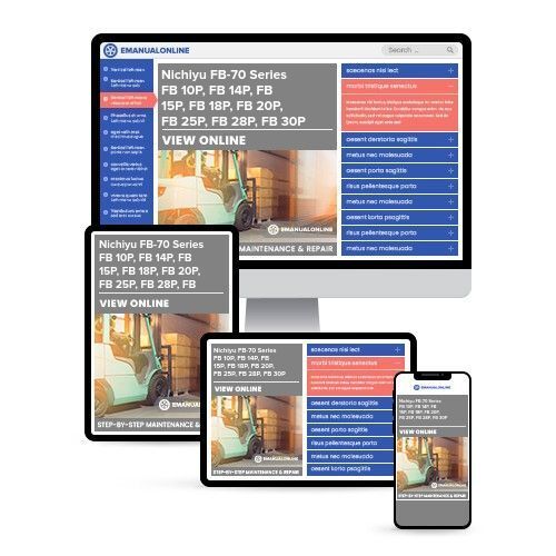
Nichiyu FB-70 Series FB 10P, FB 14P, FB 15P, FB 18P, FB 20P, FB 25P, FB 28P, FB 30P Forklift Full Service & Repair Manual
The Nichiyu FB-70 Series FB 10P, FB 14P, FB 15P, FB 18P, FB 20P, FB 25P, FB 28P, FB 30P Forklift Full Service & Repair Manual is a comprehensive resource for all your repair needs. Whether you are a professional mechanic or a DIY enthusiast, this manual provides detailed instructions for servicing, repairing, and troubleshooting the forklift.
Containing hundreds of pages with detailed photos and diagrams, this professional manual is the same type used by professional mechanics and technicians. It includes step-by-step instructions and highly detailed exploded diagrams and pictures to guide you through each job accurately.
With the ability to print out single pages or the entire manual, you have the flexibility to choose how you access the information. Additionally, this manual can be used on multiple computers without any limitations or trial periods, and it does not expire or require renewal fees.
Compatible with both Windows and MAC computers, this manual is available for instant access on your computer, tablet, or smartphone. Get your hands on this invaluable resource for all your forklift service and repair needs.
Reviews
Q&A
Recently Viewed
5,521,897Happy Clients
2,594,462eManuals
1,120,453Trusted Sellers
15Years in Business
Price:
Actual Price:
Nichiyu FB-70 Series FB 10P, FB 14P, FB 15P, FB 18P, FB 20P, FB 25P, FB 28P, FB 30P Forklift Full Service & Repair Manual







 Lifetime Access




