



Service Manual
99709-58130 For use with Chassis Service Manual.
6D16 Diesel Engine
FD80 F32B-00011-up
FD90 F32B-50001-up
FD100 F15C-50001-up
FD115 F15C-50001-up
FD135 F15C-50001-up
FD150A F24A-50011-up


diesel engine
Shop Manual
(for industrial use)
FOREWORD
This Shop Manual is published for the information and
guidance of personnel responsible for maintenance of
6D16 diesel engine, and includes procedures for
adjustment and maintenance services.
We earnestly look forward to seeing that this manual
is made full use of in order to perform correct service
with no wastage.
For more details, please consult your nearest
authorized Mitsubishi dealer or distributor.
Kindly note that the specifications and maintenance
service figures are subject to change without prior
notice in line with improvement which will be effected
from time to time in the future.
Applicable models
6D16
6D16-TLE
GROUP INDEX
HOW TO READ THIS MANUAL
GENERAL ...........................................
ENGINE ...............................................
LUBRICATION ....................................
FUEL AND ENGINE CONTROL ..........
COOLING ............................................
INTAKE AND EXHAUST ......................
ELECTRICAL SYSTEM .......................
SPECIAL EQUIPMENT .......................
00
11
12
13
14
15
54
61
Pub. No. 99709-58130

HOW TO READ THIS MANUAL
HOW THIS MANUAL IS COMPILED ii
GENERAL EXPLANATION OF THIS MANUAL iii
TERMS AND UNITS vii
i
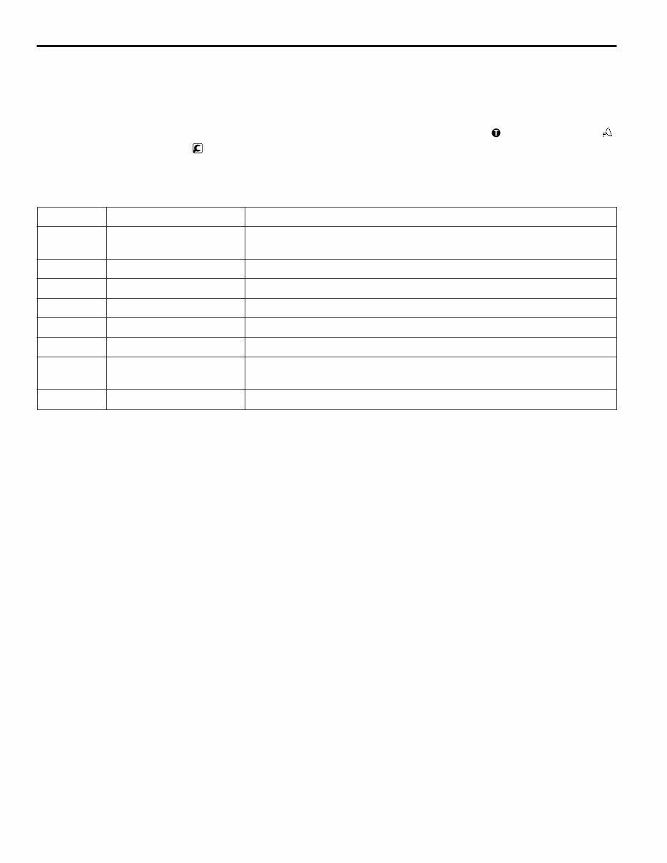
How This Manual Is Compiled
• This manual is compiled by classifying various systems into certain groups.
• Each group contains specifications; troubleshooting; maintenance service standards; tightening torque;
lubricant, fluid and sealant; special tools; and service procedure.
• Page enumeration is independent by every group where first page is always 1.
ii
HOW TO READ THIS MANUAL
Group No. Group denomination Contents
00 General General specifications, engine No. and name plate, precautions for
maintenance operations, table of standard tightening torques
11 Engine Engine body
12 Lubrication Lubrication system
13 Fuel and engine control Fuel system
14 Cooling Cooling system
15 Intake and exhaust Intake and exhaust system, intercooler
54 Electrical system Alternator, starter, preheating system, engine start system, automatic
stop system
61 Special equipment Air compressor
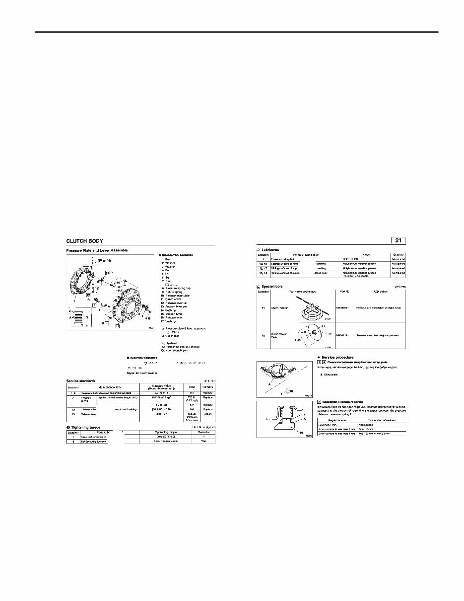
General Explanation of This Manual
● Specifications
Particulars relative to maintenance service are made.
● Structure and operation
(1) Regarding conventional equipment, descriptions are made in brief.
(2) Regarding new equipment, descriptions of system and operating condition are made in detail.
● Troubleshooting
Symptoms of troubles and possible causes are described comparatively.
● Inspection and adjustment mounted in vehicle
Descriptions are made regarding inspection and adjustment of units mounted in vehicle.
● Service procedure
In principle, an explanation is given at the spread title page so that the service procedure can be understood.
Servicing points are explained as a supplementary explanation.
Regarding the design of this manual
1. ............... Illustration for disassembly and assembly or removal and installation: 3-D exploded view of component
parts is displayed.
1a. ........ Names of parts show an example of the disassembly (removal) sequence.
1b. ........ When the assembly (installation) sequence differs from the disassembly (removal) sequence, an
example of the assembly (installation) sequence is shown.
2. ............... Service standards are shown collectively, classified by location.
3. ............... Tightening torques are shown collectively, classified by location.
4. ............... Points of lubricant, fluid and sealant application are shown collectively, classified by location.
5. ............... Special tools to be used are shown collectively, classified by location.
6. ............... When it is considered hard to understand the service procedure, just by the foregoing description, a
supplementary description of the service procedure is given.
iii
1a
1
1b
2
3
4
5
6
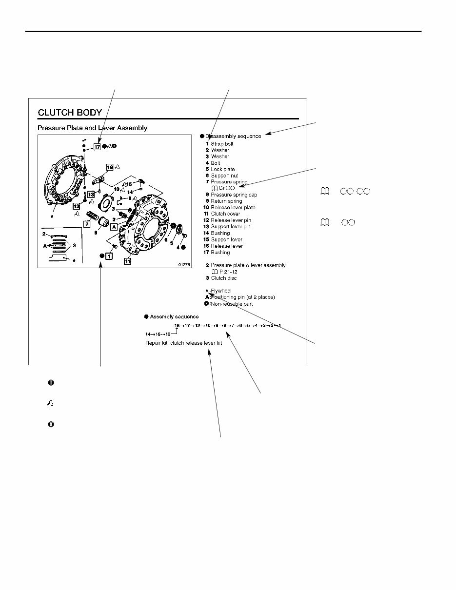
1. Illustration for disassembly and assembly or removal and installation
iv
HOW TO READ THIS MANUAL
This shows that the appropriate service
procedure is described in the text.
This shows the key No. of the part. In the text,
this No. is referred to uniformly throughout.
This shows an example of
the disassembly (removal)
sequence.
No service procedure is
referred to in this section,
but the item can be an
objective of various
procedures.
This is shown when the assembly (installation)
sequence is not the reverse of the disassembly
(removal) sequence.
Meaning of symbols
: shows that the tightening torque is
specified.
: shows that application of lubricant,
fluid or sealant is required.
: shows that the part should not be
reused.
This shows that a repair kit is available.
This shows that the service
procedure is described in
another section.
P. -
: shows reference page
within the same group.
Gr
: shows reference group
within the same book.
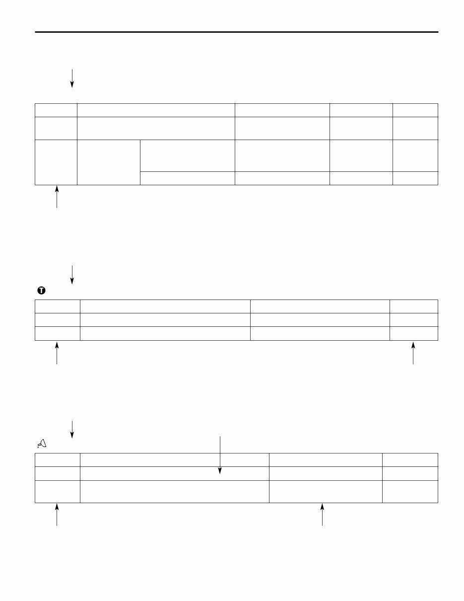
2. Service standards table
Service standards Unit: mm (in.)
3. Tightening torque table
Tightening torques Unit: N·m (kgf·m) [lbf·ft]
4. Lubricants and sealant table
Lubricants and sealant
Location Maintenance item Standard value Limit Remedy
1, 11 Clearance between strap bolt and strap 0.01 to 0.16 0.3 (0.0118) Replace
plate (0.0039 to 0.0629)
7 Pressure spring Installed load 835 N 710 N Replace
(Installed length 49.1) (85 kgf) (72.3 kgf)
[187.7 lbf] [159.6 lbf]
Tilt 2.9 (1.1417) or less 5.0 (0.197) Replace
v
Only the relevant service standards are shown.
This shows the key No. of the relevant part.
This shows specified tightening torque.
This shows the key No. of the relevant part. This shows that the item
is to be tightened wet.
Only the relevant lubricants and sealant are shown.
This shows the application point.
This shows the key No. of the relevant part. This shows the specified brand.
Location Parts to be tightened Tightening torque Remarks
1 Strap bolts (Strap bolt mounting) 39 to 59 (4 to 6) [28.8 to 43.5] –
4 Bolt (Lock plate mounting) 5.9 to 7.8 (0.6 to 0.8) [4.3 to 10.5] Wet
Location Points of application Kinds Quantity
1 Thread area of bolt LOCTITE 272 As required
10, 16 Friction surfaces of release lever plate and release Molybdenum disulfide grease As required
lever [NLGI No. 2 (Li soap)]
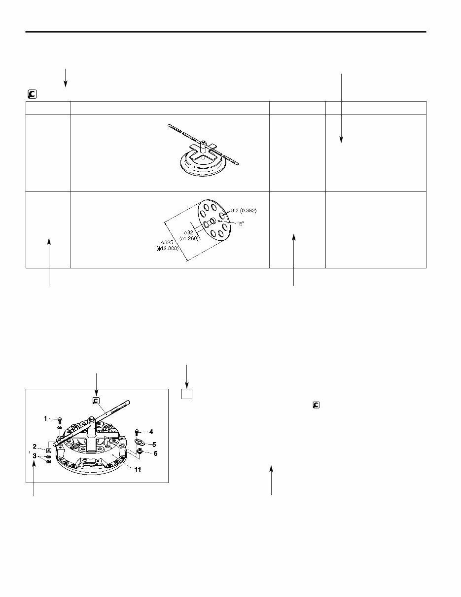
5. Special tools table
Special tools Unit: mm (in.)
6. Service procedure
Removal and installation of clutch cover
• Depress pressure spring 7 using clutch installer, then remove
the following parts:
Strap bolt 1, washer 2, washer 3, bolt 4, lock plate 5, support nut 6
• Loosen the clutch installer gradually, then remove clutch cover 11
when the pressure spring is fully released.
• For installation, follow the removal sequence in reverse.
11
vi
HOW TO READ THIS MANUAL
Only the relevant special tools are shown. Purpose of special tools is shown.
This shows the key No. of the relevant part. Quote this number when placing
an order for the part.
This shows the key No. of the relevant part.
Servicing procedures of disassembly (removal),
assembly (installation), inspection, adjustment,
etc. are shown collectively.
The key No. referred to in the text is always the
same as the key No. shown in the illustration.
This indicates a special
service tool.
Location Tool name and shape Part No. Application
11 Clutch installer MH061051
Removal and installation of
clutch cover
16 Master plate MH062291
Adjust release lever
heights
01277
01278
01281

Terms and Units
The terms and units in this manual are defined as follows.
● This service manual contains important cautionary instructions and supplementary information under the following
four headings which identify the nature of the instructions and information:
DANGER
WARNING
CAUTION
NOTE
● Front and rear
The terms “front” is the fan side and “rear” the flywheels side of the engine.
● Left and right
The terms “right” and “left” shall be used to indicate the side as viewed from the flywheel side of the engine.
● Terms of service standards
(1) Standard value
Standard value dimensions in designs indicating: the design dimensions of individual parts, the standard
clearance between two parts when assembled, and the standard value for an assembly part, as the case may be.
The figure in [ ] is the basic diameter.
(2) Limit
When the value of a part exceeds this, it is no longer serviceable in respect of performance and strength and
must be replaced or repaired.
● Tightening torque
Excessive or insufficient tightening torque has particular importance in respect of performance. Accordingly,
tightening torque is specified in locations that are to be tightened.
Where there is no specified figure for tightening torque, follow the table covering standard tightening torques.
When the item is to be tightened in a wet state, wet is indicated. Where there is no indication, read it as dry, and
tighten at specified torque.
● Unit
Length, weight, surface area and capacity are in SI units with foot-pound units are given in brackets.
Tightening torques and other parameters are given in SI units with metric and foot-pound units added in brackets ( )
and [ ].
Example: 390 N·m (40 kgf·m) [289 lbf·ft]
Temperatures are given in degrees Celsius with degrees Fahrenheit given brackets.
For the conversion into the foot-pound system, refer to the following conversion table.
vii
Precautions that should be taken in handling potentially dangerous substances such
as battery fluid and coolant additives.
Precautionary instructions, which, if not observed, could result in serious injury or
death.
Precautionary instructions, which, if not observed, could result in damage to or
destruction of equipment or parts.
Suggestions or supplementary information for more efficient use of equipment or a
better understanding.
SI unit
Metric unit
Foot-pound unit
You're Reading a Preview
What's Included?
 Lifetime Access
Fast Download Speeds
Online & Offline Access
Access PDF Contents & Bookmarks
Full Search Facility
Print one or all pages of your manual
$40.99
Mitsubishi Forklift Trucks FD80, FD90, FD100, FD115, FD135, FD150A Service Repair Manual
Viewed 61 Times Today

What's Included?
Lifetime Access
Fast Download Speeds
Online & Offline Access
Access PDF Contents & Bookmarks
Full Search Facility
Print one or all pages of your manual
$40.99

Secure transaction
What's Included?
Lifetime Access
Fast Download Speeds
Online & Offline Access
Access PDF Contents & Bookmarks
Full Search Facility
Print one or all pages of your manual
Description
Get your hands on the comprehensive service repair manual for Mitsubishi Forklift Trucks, including Models FD80 F32B-00011-up, FD90 F32B-50001-up, FD100 F15C-50001-up, FD115 F15C-50001-up, FD135 F15C-50001-up, and FD150A F24A-50011-up, along with the 6D16 Diesel Engine.
- Chassis and Mast: Electrical System
- Chassis and Mast: Electrical System: Schematic
- Chassis and Mast: Power Train
- Chassis and Mast: 2-Speed Powershift Transmission
- Chassis and Mast: 3-Speed Powershift Transmission
- Chassis and Mast: Front Axle and Reduction Differential
- Chassis and Mast: Rear Axle
- Chassis and Mast: Brake System
- Chassis and Mast: Steering System
- Chassis and Mast: Hydraulic System
- Chassis and Mast: Mast and Forks
- Chassis and Mast: Hydraulic Fork Positioners
- Chassis and Mast: Hydraulic Side Shifters
- Chassis and Mast: Service Data
- 6D16 Diesel Engine: Foreward
- 6D16 Diesel Engine: How to Read This Manual
- 6D16 Diesel Engine: General
- 6D16 Diesel Engine: Engine
- 6D16 Diesel Engine: Lubrication
- 6D16 Diesel Engine: Fuel and Engine Control
- 6D16 Diesel Engine: Cooling
- 6D16 Diesel Engine: Intake and Exhaust
- 6D16 Diesel Engine: Electrical System
- 6D16 Diesel Engine: Special Equipment
This manual comes in a printable format and is available in English, making it an essential resource for both professional mechanics and DIY enthusiasts.


