FOREWORD This service manual is a guide to servicing of Mitsubishi forklift trucks. The instructions are grouped by systems to serve the convenience of your ready reference. Long productive life of your forklift trucks depends to a great extent on correct servicing — servicing consistent with what you will learn from this service manual. Read the respective sections of this manual carefully and familiarize yourself with all the components you will work on, before attempting to start a test, repair or rebuild job. The descriptions, illustrations and specifications contained in this manual are of the trucks with the serial numbers in effect at the time it was approved for printing. Mitsubishi forklift truck reserves the right to change specifications or design without notice and without incurring obligation. Pub. No. 99759-7C110 Safety Related Signs The following safety related signs are used in this service manual to emphasize important and critical instructions: Indicates a specific potential hazard that could result in serious bodily injury or death. Indicates a specific potential hazard that may result in bodily injury, or damage to, or destruction of, the machine. Indicates a condition that can cause damage to, or shorten service life of, the machine. NOTE WARNING ! CAUTION !
The serviceman or mechanic may be unfamiliar with many of the systems on this truck. This makes it important to use caution when performing service work. A knowledge of the system and/or components is important before the removal or disassembly of any component. Because of the size of some of the truck components, the serviceman or mechanic should check the weights noted in this Manual. Use proper lifting procedures when removing any components. Following is a list of basic precautions that should always be observed. 1. Read and understand all warning plates and decals on the truck before operating, lubricating or repairing the product. 2. Always wear protective glasses and protective shoes when working around trucks. In particular, wear protective glasses when pounding on any part of the truck or its attachments with a hammer or sledge. Use welders gloves, hood/goggles, apron and other protective clothing appropriate to the welding job being performed. Do not wear loose- fitting or torn clothing. Remove all rings from fingers when working on machinery. 3. Do not work on any truck that is supported only by lift jacks or a hoist. Always use blocks or jack stands to support the truck before performing any disassembly. 4. Lower the forks or other implements to the ground before performing any work on the truck. If this cannot be done, make sure the forks or other implements are blocked correctly to prevent them from dropping unexpectedly. 5. Use steps and grab handles (if applicable) when mounting or dismounting a truck. Clean any mud or debris from steps, walkways or work platforms before using. Always face truck when using steps, ladders and walkways. When it is not possible to use the designed access system, provide ladders, scaffolds, or work platforms to perform safe repair operations. 6. To avoid back injury, use a hoist when lifting components which weigh 23 kg (50 lb.) or more. Make sure all chains, hooks, slings, etc., are in good condition and are of the correct capacity. Be sure hooks are positioned correctly. Lifting eyes are not to be side loaded during a lifting operation. 7. To avoid burns, be alert for hot parts on trucks which have just been stopped and hot fluids in lines, tubes and compartments. 8. Be careful when removing cover plates. Gradually back off the last two bolts or nuts located at opposite ends of the cover or device and pry cover loose to relieve any spring or other pressure, before removing the last two bolts or nuts completely. 9. Be careful when removing filler caps, breathers and plugs on the truck. Hold a rag over the cap or plug to prevent being sprayed or splashed by liquids under pressure. The danger is even greater if the truck has just been stopped because fluids can be hot. SAFETY The proper and safe lubrication and maintenance for this forklift truck, recommended by Mitsubishi forklift truck, are outlined in the OPERATION & MAINTENANCE MANUAL for these trucks. Improper performance of lubrication or maintenance procedures is dangerous and could result in injury or death. Read and understand the OPERATION & MAINTENANCE MANUAL before performing any lubrication or maintenance. WARNING ! Do not operate this truck unless you have read and understand the instructions in the OPERATION & MAINTENANCE MANUAL. Improper truck operation is dangerous and could result in injury or death. WARNING ! WARNING !
10. Always use tools that are in good condition and be sure you understand how to use them before performing any service work. 11. Reinstall all fasteners with same part number. Do not use a lesser quality fastener if replacements are necessary. 12. If possible, make all repairs with the truck parked on a level, hard surface. Block truck so it does not roll while working on or under truck. 13. Disconnect battery and discharge any capacitors (electric trucks) before starting to work on truck. Hang “Do not Operate” tag in the Operator’s Compartment. 14. Repairs, which require welding, should be performed only with the benefit of the appropriate reference information and by personnel adequately trained and knowledgeable in welding procedures. Determine type of metal being welded and select correct welding procedure and electrodes, rods or wire to provide a weld metal strength equivalent at least to that of parent metal. 15. Do not damage wiring during removal operations. Reinstall the wiring so it is not damaged nor will it be damaged in operation by contacting sharp corners, or by rubbing against some object or hot surface. Place wiring away from oil pipe. 16. Be sure all protective devices including guards and shields are properly installed and functioning correctly before starting a repair. If a guard or shield must be removed to perform the repair work, use extra caution. 17. Always support the mast and carriage to keep carriage or attachments raised when maintenance or repair work is performed, which requires the mast in the raised position. 18. Loose or damaged fuel, lubricant and hydraulic lines, tubes and hoses can cause fires. Do not bend or strike high pressure lines or install ones which have been bent or damaged. Inspect lines, tubes and hoses carefully. Do not check for leaks with your hands. Pin hole (very small) leaks can result in a high velocity oil stream that will be invisible close to the hose. This oil can penetrate the skin and cause personal injury. Use cardboard or paper to locate pin hole leaks. 19. Tighten connections to the correct torque. Make sure that all heat shields, clamps and guards are installed correctly to avoid excessive heat, vibration or rubbing against other parts during operation. Shields that protect against oil spray onto hot exhaust components in event of a line, tube or seal failure, must be installed correctly. 20. Relieve all pressure in air, oil or water systems before any lines, fittings or related items are disconnected or removed. Always make sure all raised components are blocked correctly and be alert for possible pressure when disconnecting any device from a system that utilizes pressure. 21. Do not operate a truck if any rotating part is damaged or contacts any other part during operation. Any high speed rotating component that has been damaged or altered should be checked for balance before reusing. 22. When handling the parts containing asbestos, be careful not to inhale the asbestos. Doing so is hazardous to your health. If the shop dust may contain asbestos, follow the precautions described below. a. Do not use compressed air for cleaning. b. Do not brush or apply grinder on asbestos containing materials. c. To clean asbestos containing materials, wipe with moistened cloth or use a vacuum cleaner with particle filter. d. If you have to handle the parts containing asbestos for a long time, be sure to do it in a well-ventilated area. e. If the asbestos in the air cannot be removed, wear a mask. f. Be sure to observe the working rules and regulations. g. When disposing of materials with asbestos, be sure to observe the environmental protection regulations of your area. h. Avoid working in the atmosphere where asbestos particles may be suspended.
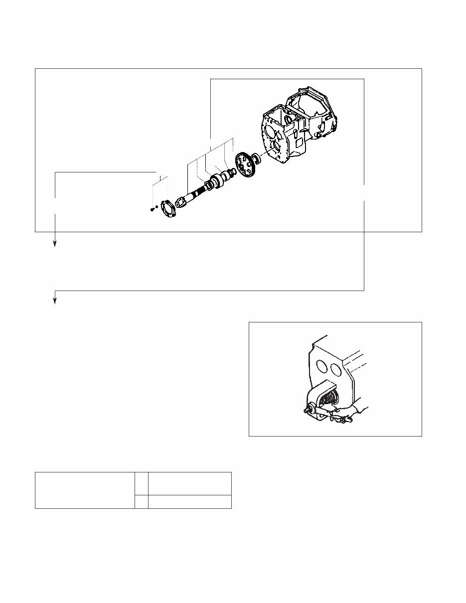
HOW TO USE THIS MANUAL (Removal, Installation, Assembly and Disassembly) Disassembly diagram (example) Suggestion for disassembling 1. Output shaft, Removing Remove output shaft using a special tool. Service Data A: Standard Value B: Repair or Service Limit 1 2 209603 Sequence 1 Cover , Bolt, Washer (part name) 2 Snap ring ................ (part name) A 0.11 to 0.28 mm Gear Backlash (0.0043 to 0.0110 in.) B 0.5 mm (0.020 in.) 209604 Disassembling sequence Procedures are described in the text.
Symbols or abbreviation OP Option R1/4 Taper pipe thread (external) 1/4 inch (formerly PT1/4) Rc1/8 Taper pipe thread (internal) 1/8 inch (formerly PT1/8) G1/4A Straight pipe thread (external) 1/4 inch (formerly PF1/4-A) Rp1/8 Straight pipe thread (internal) 1/8 inch (formerly PS1/8) Units 1. SI Units are used in this manual. 2. The following table shows the conversion of SI unit and customary unit. Item SI unit Customary unit Force 1 N 0.1020 kgf (1 lbf) (0.4536 kgf) Pressure 1 kPa 0.0102 kgf/cm 2 (1 psi) (0.0703 kgf/cm 2 ) Torque 1 N·m 0.1020 kgf·m (1 lbf·ft) (0.1383 kgf·m)
GROUP INDEX Items Controller system, Controller features, Setup option, Diagnosis, Removal and CONTROLLER installation, Basic check TROUBLESHOOTING Faulty central vehicle monitor system, Faulty diagnosis indication, FOR CONTROL or Other abnormalities CIRCUITS Motor installation positions, Specifications, Structures, Tightening of high-power MOTORS cable terminals, Procedures and suggestions for removal and installation, Procedures and suggestions for disassembly and reassembly GROUP INDEX 1 2 3
Controller System .................................................................................... 1 – 1 System Configuration ............................................................................... 1 – 1 Controller Area Network (CAN) ................................................................. 1 – 3 Outline of Controller ................................................................................. 1 – 5 Controller Features ................................................................................. 1 – 8 Traction Control Features ......................................................................... 1 – 8 Lifting Control Features ............................................................................ 1 – 11 Steering Control Features ......................................................................... 1 – 11 Diagnosis/Run/Setup (DRS) Modes .......................................................... 1 – 12 Safety Function ........................................................................................ 1 – 16 Other Features .......................................................................................... 1 – 18 Setup Option ............................................................................................ 1 – 19 Outline ...................................................................................................... 1 – 19 Operation Procedure ................................................................................ 1 – 19 Details of Setup Options ........................................................................... 1 – 21 Diagnosis .................................................................................................. 1 – 38 Outline ...................................................................................................... 1 – 38 Operation Procedure ................................................................................ 1 – 38 Self-Diagnostics (Hydraulic control: Transistor Control Type) ................... 1 – 41 Self-Diagnostics (Hydraulic control: Contactor Control Type) ................... 1 – 42 Run Time Diagnostics ............................................................................... 1 – 43 Removal and Installation ....................................................................... 1 – 45 Inverter Discharging Procedure ................................................................ 1 – 45 Replacing Inverter ..................................................................................... 1 – 46 Insuring Proper Thermal Transfer ............................................................... 1 – 46 Replacing DSP (Digital Signal Processor) Card ........................................ 1 – 52 Replacing Logic Unit ................................................................................ 1 – 54 Replacing Logic Card ............................................................................... 1 – 55 Replacing Power Supply Card .................................................................. 1 – 56 1 CONTROLLER
This workshop service repair manual is an essential resource for maintaining and repairing Mitsubishi FBC15N, FBC18N, FBC18LN, FBC20N, FBC25EN, FBC25N, FBC25LN, FBC30N, and FBC30LN controller forklift trucks. It is a valuable tool for both professional mechanics and DIY enthusiasts.
Model Name and Series:
Mitsubishi Forklift FBC15N A4BC1-10200-UP
Mitsubishi Forklift FBC18N A4BC1-20200-UP
Mitsubishi Forklift FBC18LN A4BC1-30200-UP
Mitsubishi Forklift FBC20N A4BC2-10200-UP
Mitsubishi Forklift FBC25EN A4BC3-20200-UP
Mitsubishi Forklift FBC25N A4BC2-20200-UP
Mitsubishi Forklift FBC25LN A4BC3-30200-UP
Mitsubishi Forklift FBC30N A4BC3-40200-UP
Mitsubishi Forklift FBC30LN A4BC4-10200-UP
This manual covers:
Controller: Foreword
Controller: Controller
Controller: Troubleshooting for Control Circuits
Controller: Troubleshooting for Control Circuits Schematics
Controller: Motors
It is available in PDF format and can be accessed on all versions of Windows and Mac, as well as on mobile devices such as iPhone, iPod, and Android. The language of the manual is English, and it requires Adobe Reader for viewing. This instant download eliminates shipping costs and waiting time, providing immediate access upon secure payment processing. The manual is printable, making it a convenient and cost-saving resource for understanding and maintaining your Mitsubishi forklift.











 Lifetime Access




