
 Manual")
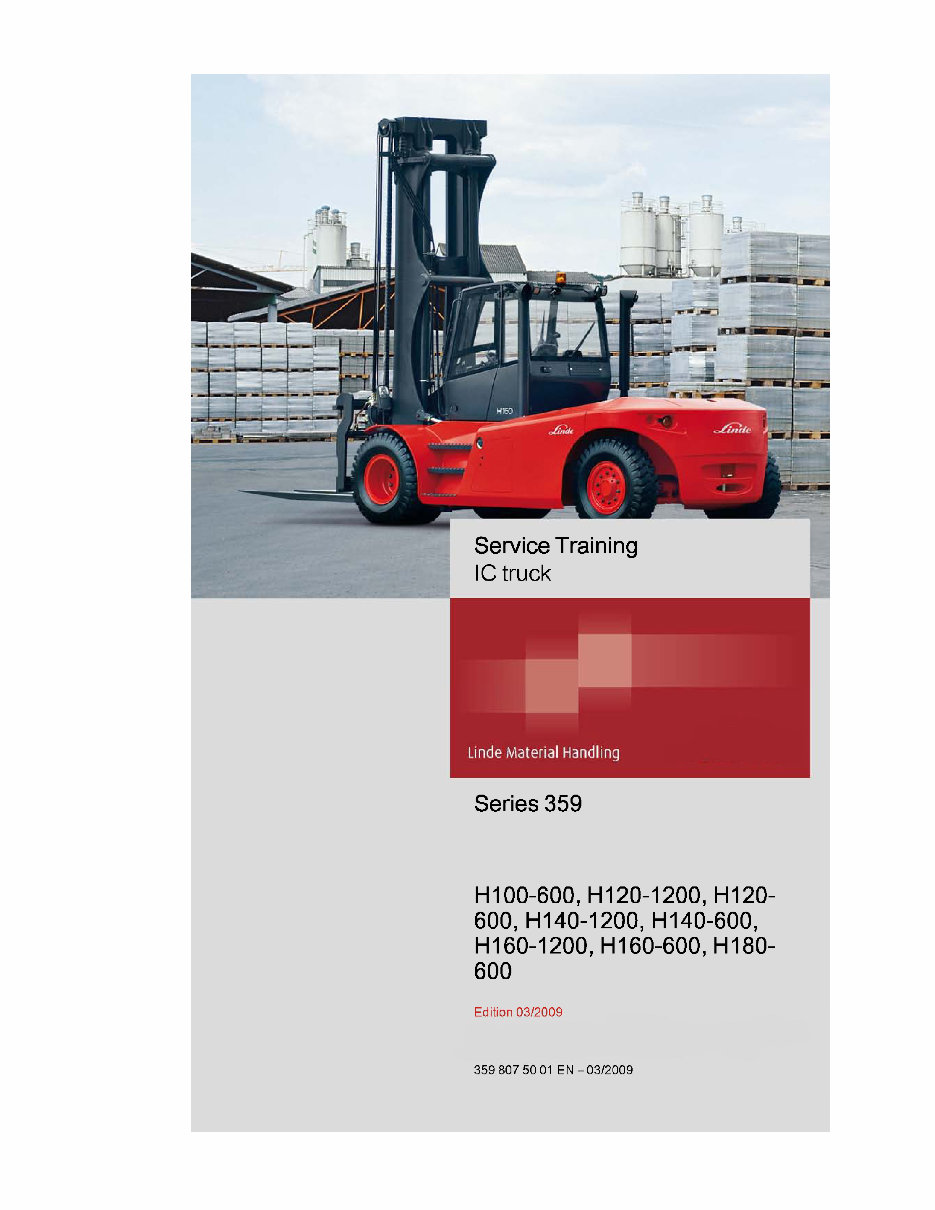
Linde Forklift Truck Type 359: H100, H120, H140, H160, H180 Service Training (Workshop) Manual
What's Included?
Fast Download Speeds
Online & Offline Access
Access PDF Contents & Bookmarks
Full Search Facility
Print one or all pages of your manual

You're Reading a Preview
What's Included?
Fast Download Speeds
Online & Offline Access
Access PDF Contents & Bookmarks
Full Search Facility
Print one or all pages of your manual
$42.99
Viewed 35 Times Today


Secure transaction
What's Included?
Fast Download Speeds
Online & Offline Access
Access PDF Contents & Bookmarks
Full Search Facility
Print one or all pages of your manual
$42.99
- Original Illustrated Factory Service Training (Workshop) Manual for Linde Forklift Truck Type 359.
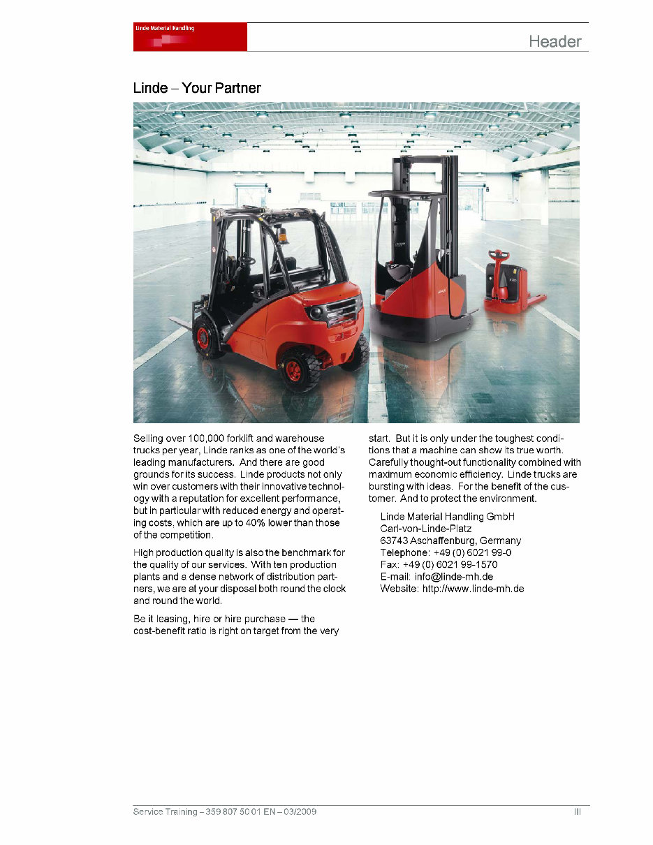
- Original factory manuals for Linde Forklift Trucks, containing high-quality images, circuit diagrams, and instructions to help you operate and repair your truck.
- Useful for both professional mechanics and DIY enthusiasts.
- Covered models:
- H100-600
- H120-1200
- H120-600
- H140-1200
- H140-600
- H160-1200
- H160-600
- H180-600
- Format: 261 Pages, Printable
- Language: English
- Contents:
- Product information
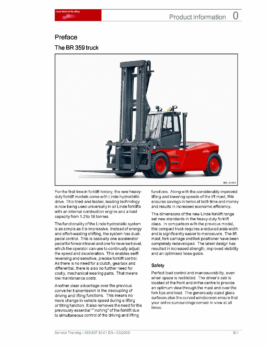
- Preface
- The BR 359 truck
- Technical data
- Dimensions
- VDI datasheet H100-600, H120-600, H140-600
- VDI datasheet H150-600, H160-600, H180-600
- VDI datasheet H120-1200, H140-1200, H160-1200
- Diagnostics
- LTC basic structure
- CAN bus communication overview and installation position
- Error code lists
- Indicator unit error codes
- LTC traction control codes, versionl.X
- LTC lift control codes, 0.040 version, LTC module N1
- LTC lift control codes, Version 0.040, LTC module N2
- Cummins diesel engine fault codes
- Engine
- Diesel engine QSB 5.9
- Description of the drive
- Technical data
- View of engine
- Engine identification
- Engine data plate
- Injection pump plate
- Engine control unit data plate
- Cylinder head
- Installing, removing, and checking the cylinder head
- Rocker levers and pushrods
- Installing, removing, and checking valves
- Valve clearance
- Cylinder block
- Front crankshaft sealing ring
- Renewing the oil sump seal
- Fuel supply
- Removing and refitting the injection pump
- Exhaust system
- Removing, installing, and checking the turbocharger
- Installing, removing, and checking the exhaust manifold
- Diesel engine QSB 6.7
- Fuel supply
- Removing and installing injectors
- Checking the fuel supply
- Removing and installing the EFC actuator
- Removing and installing the high-pressure pump
- Removing and installing the rail
- Engine block
- Removing and fitting the V-ribbed belt
- Removing and installing the exhaust turbocharger
- Removing, installing, and checking the exhaust manifold
- Removing and installing the valve cover
- Adjusting the valve clearance
- Checking rocker levers and pushrods
- Removing, installing, and checking the cylinder head
- Removing, installing, and checking valves
- Changing the oil sump seal
- Diesel engine QSB 5.9
- Drive axle
- Description
- Technical data for traction drive
- Schematic view of the drive
- Linde TruckControl (LTC)
- Traction drive
- Travel drive - introduction
- Introduction
- Variable displacement pump controller
- Motor variables controller
- Pedal group
- Variable displacement pump
- HPV 210-02 variable displacement pump
- Electro-hydraulic remote control
- Variable pump advance start
- Variable motor
- Variable motor HMV210-02 and HMV 280-02
- Output unit function characteristics
- Reduction gearbox
- Reduction gearbox GR 26-01
- Brake
- Braking process - function characteristics
- Retarder valve block components
- Retarder valve block function
- Brake release valve
- Towing unit
- Checking the brake system
- Hydraulic fan drive
- Function characteristics
- Checking the hydraulic fan drive
- Chassis, bodywork, and fittings
- Steering system
- Function characteristics
- Steering axle
- Stub axle
- Wheel hub
- Adjusting the inner steering stop
- Adjusting the outer steering stop
- Removing and installing the steering cylinder
- Sealing the steering cylinder
- Controls
- Display elements
- Indicator unit
- Electrics / Electronics
- Central electrical system
- Arrangement of relays and fuses for basic equipment and special equipment
- Checks
- Testing the electronic controllers and components
- Testing the LTC (vehicle and lift controller)
- Checking wiring harness
- Testing sensors
- Checking actuators
- Testing the indicator unit
- Hydraulics
- Regulating pump HPR210-02
- Technical data for regulating pump
- HPR 210-02 regulating pump
- Load sensing regulation
- Working hydraulic
- Working hydraulic circuit diagram
- Hose layout
- Hose layout, supply, valve block, working hydraulics
- Hose layout lifting/lowering
- Tilting hose layout
- Hose layout for sideshift and fork positioner
- Measurements and settings
- Checking the maximum working pressure and LS pressure
- Checking and adjusting delta pressure P to LS
- Tilting the cab
- Cabin tilting mechanism
- Operation of the cab tilt device
- Annex
- Circuit diagrams
- Hydraulic circuit diagrams
- Hydraulic circuit diagram
- Wiring diagrams QSB 5.9
- Wiring diagram parti
- Wiring diagram Part 2
- Wiring diagram Part 3
- Wiring diagram part 4
- Wiring diagram part 5
- Wiring diagram Part 6
- Wiring diagram part 7
- Wiring diagram Part 8
- Wiring diagram part 9
- Wiring diagram part 10
- Wiring diagrams QSB 6.7
- Wiring diagram, sheet 1
- Wiring diagram, sheet 2
- Wiring diagram, sheet 3
- Wiring diagram, sheet 4 - dipped beam, sidelight, direction indicator and hazard warning light, reverse light
- Wiring diagram, sheet 5 - work lights, horn, interior light, cigarette lighter, radio
- Wiring diagram, sheet 6 - windscreen wiper motors
- Wiring diagram, sheet 7 - seat heater, flashing beacon, brake light, programmable rooflight/ beacon, mast speed limit
- Wiring diagram, sheet 8 - cabin tilting mechanism, door release, spare fuses
- Wiring diagram, sheet 9 - air conditioning
- Wiring diagram, sheet 10 - twistlocks, extend/retract, sideshift, worklights, safety override
- Circuit diagrams
- Product information


