

Linde Forklift Truck 352 Series: H35, H40, H45 Service Training Manual.
What's Included?
Fast Download Speeds
Online & Offline Access
Access PDF Contents & Bookmarks
Full Search Facility
Print one or all pages of your manual

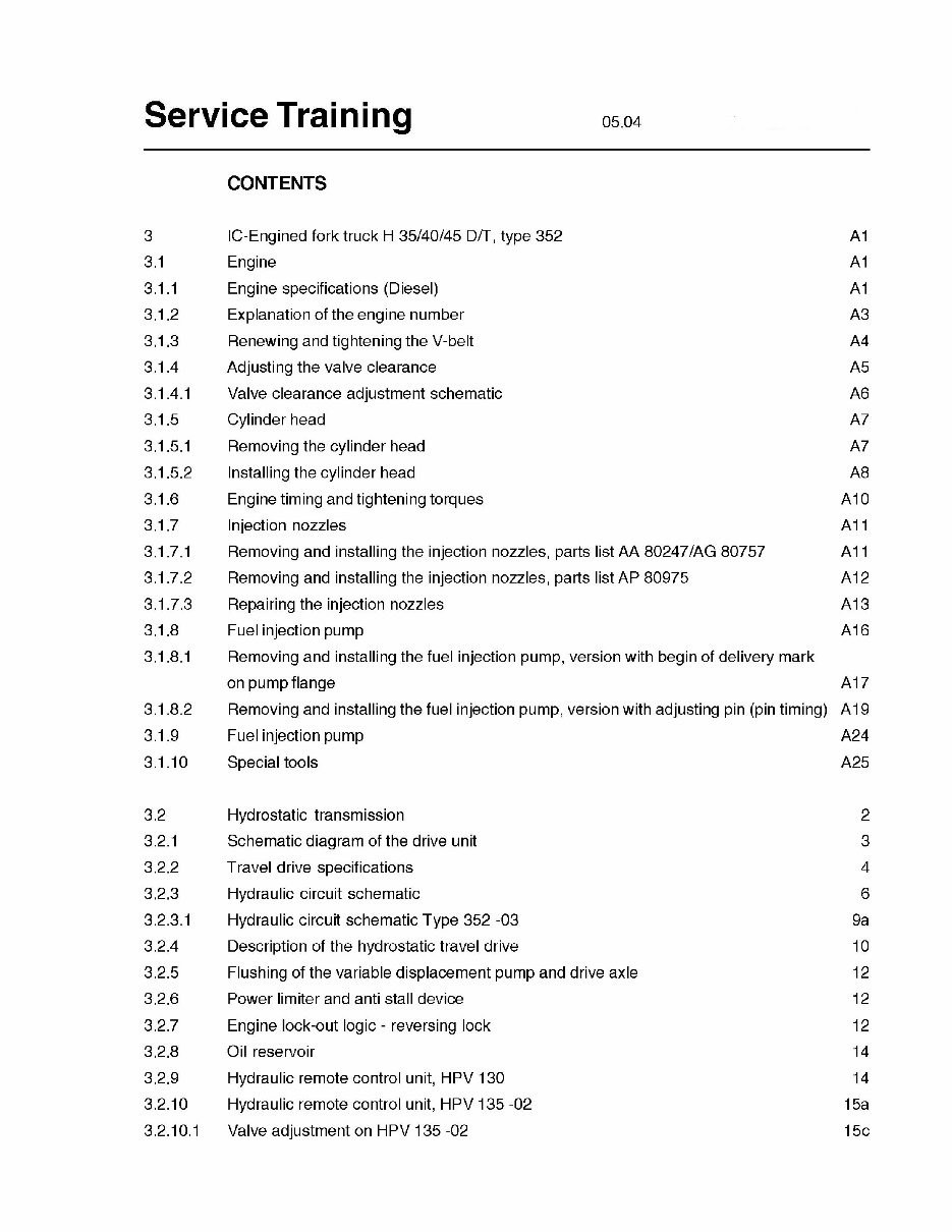
Service Training
CONTENTS
3 IC-Engined fork truck H 35/40/45 D/T, type 352 A1
3,1
Engine A1
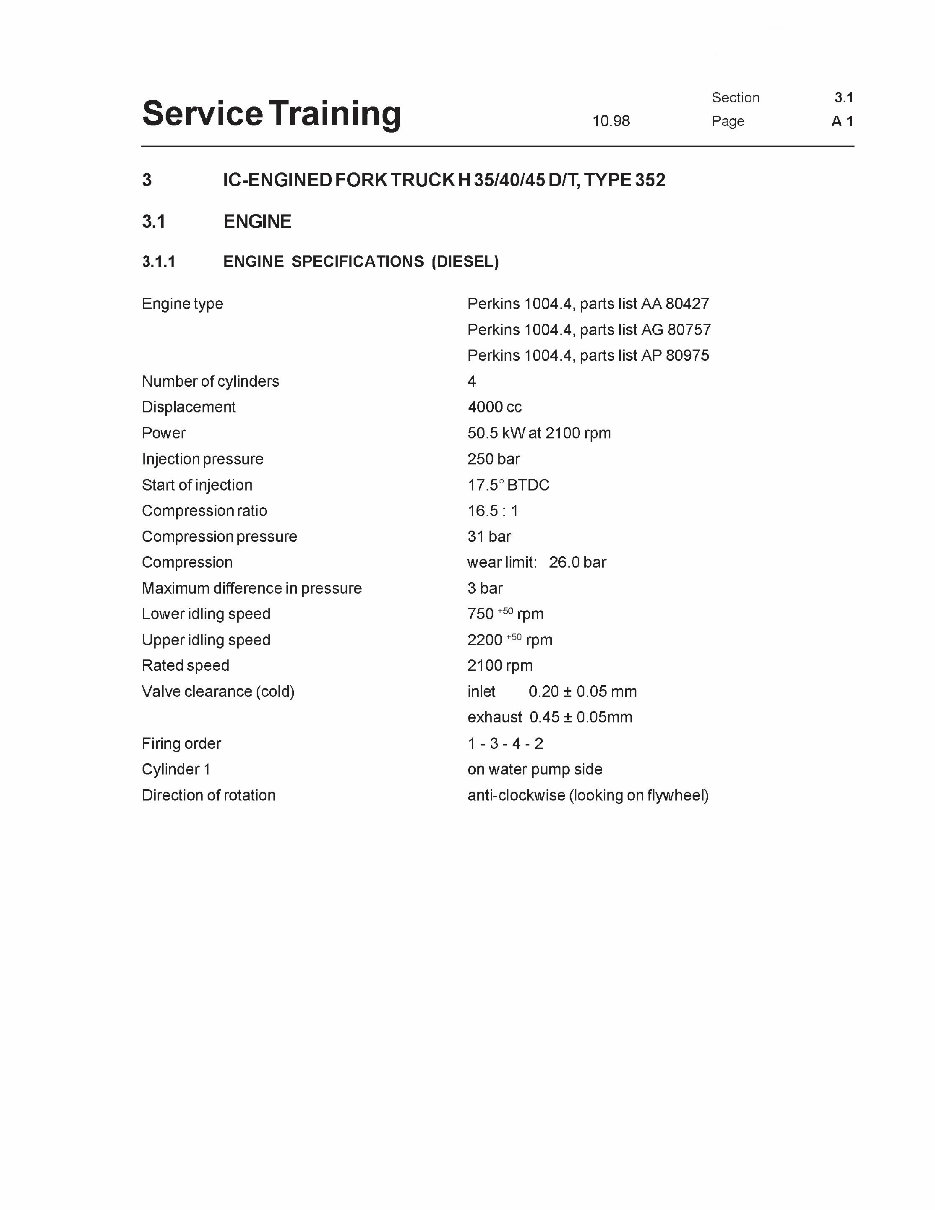
3.1.1 Engine specifications (Diesel) A1
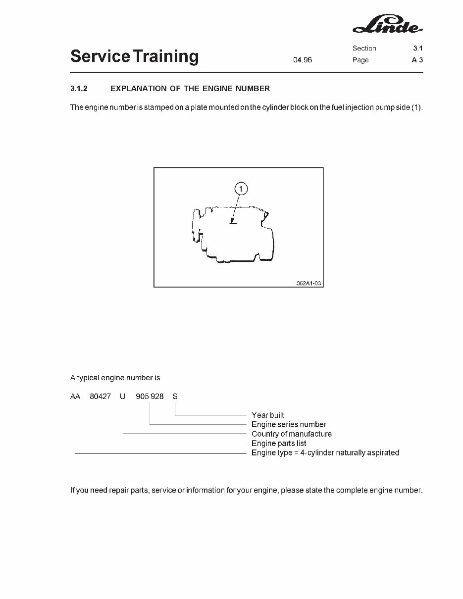
3.1.2 Explanation of the engine number A3
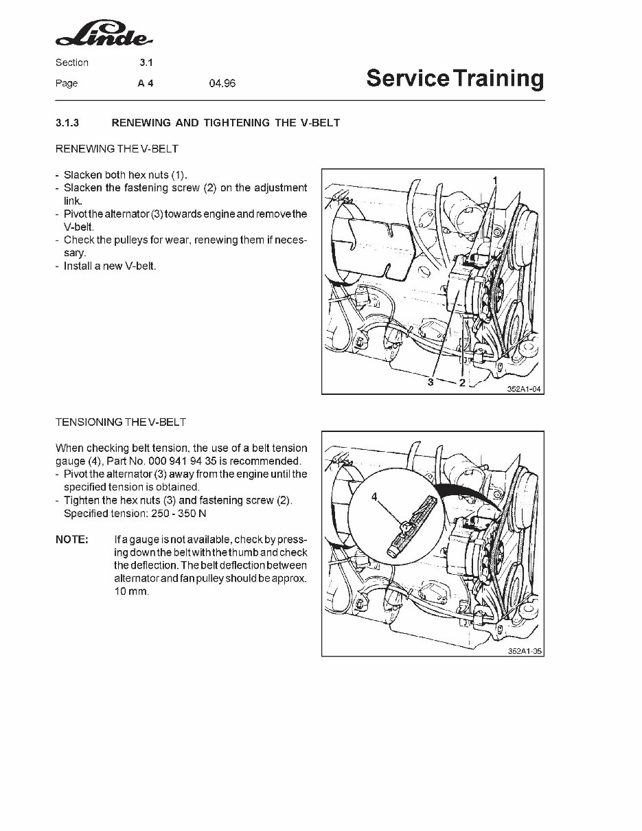
3,1.3 Renewing and tightening the V-belt A4
3.1.4 Adjusting the valve clearance A5
3.1.4.1 Valve clearance adjustment schematic A6
3.1.5 Cylinder head A7
3.1.5.1 Removing the cylinder head A7
3.1.5.2 Installing the cylinder head A8
3.1.6 Engine timing and tightening torques A10
3.1.7 Injection nozzles A11
3.1.7.1 Removing and installing the injection nozzles, parts list AA 80247/AG 80757 A11
3.1.7.2 Removing and installing the injection nozzles, parts list AP 80975 A12
3.1.7.3 Repairing the injection nozzles A13
3.1.8 Fuel injection pump A16
3.1.8.1 Removing and installing the fuel injection pump, version with begin of delivery mark
on pump flange A17
3.1.8.2 Removing and installing the fuel injection pump, version with adjusting pin (pin timing) A19
3.1.9 Fuel injection pump A24
3.1.10 Special tools A25
3.2 Hydrostatic transmission 2
3.2.1 Schematic diagram of the drive unit 3
3.2.2 Travel drive specifications 4
3.2.3 Hydraulic circuit schematic 6
3.2.3.1 Hydraulic circuit schematic Type 352 -03 9a
3.2.4 Description of the hydrostatic travel drive 10
3.2.5 Flushing of the variable displacement pump and drive axle 12
3.2.6 Power limiter and anti stall device 12
3.2.7 Engine lock-out logic - reversing lock 12
3.2.8 Oil reservoir 14
3.2.9 Hydraulic remote control unit, HPV 130 14
3,2.10 Hydraulic remote control unit, HPV 135 -02 15a
3.2.10,1 Valve adjustment on HPV 135 -02 15c
05.04 Service Training
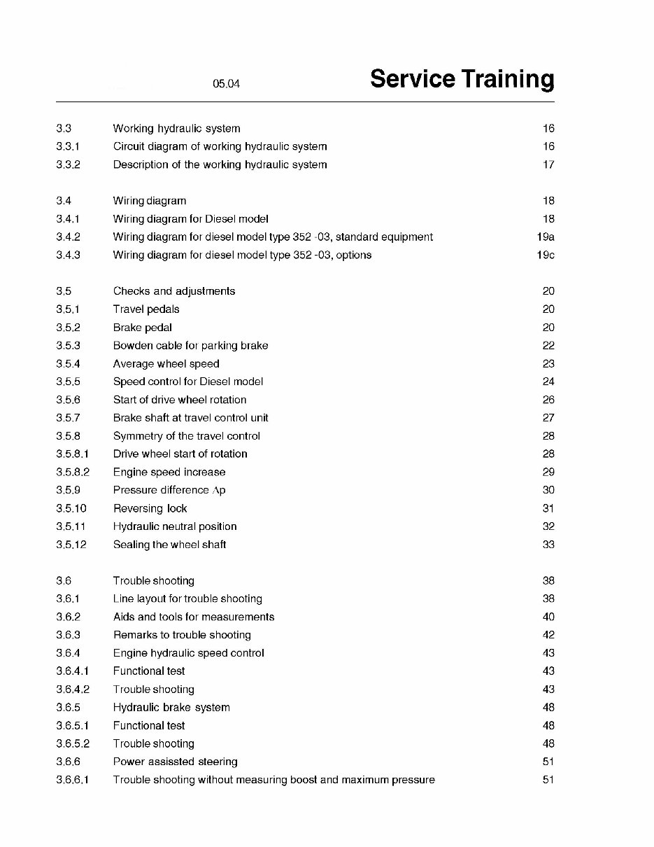
3.3 Working hydraulic system 16
3.3.1 Circuit diagram of working hydraulic system 16
3.3.2 Description of the working hydraulic system 17
3,4 Wiring diagram 18
3.4.1 Wiring diagram for Diesel model 18
3.4.2 Wiring diagram for diesel model type 352 -03, standard equipment 19a
3.4.3 Wiring diagram for diesel model type 352 -03, options 19c
3.5 Checks and adjustments 20
3.5.1 Travel pedals 20
3.5.2 Brake pedal 20
3.5.3 Bowden cable for parking brake 22
3.5.4 Average wheel speed 23
3.5.5 Speed control for Diesel model 24
3.5.6 Start of drive wheel rotation 26
3.5.7 Brake shaft at travel control unit 27
3.5.8 Symmetry of the travel control 28
3.5.8.1 Drive wheel start of rotation 28
3.5.8.2 Engine speed increase 29
3.5.9 Pressure difference Ap 30
3.5.10 Reversing lock 31
3.5.1 1 Hydraulic neutral position 32
3.5.12 Sealing the wheel shaft 33
3.6 Troubleshooting 38
3.6.1 Line layout for trouble shooting 38
3.6.2 Aids and tools for measurements 40
3.6.3 Remarks to trouble shooting 42
3.6.4 Engine hydraulic speed control 43
3.6.4.1 Functional test 43
3.6.4.2 Troubleshooting 43
3.6.5 Hydraulic brake system 48
3.6.5.1 Functional test 48
3.6.5.2 Troubleshooting 48
3.6,6 Power assissted steering 51
3.6.6.1 Trouble shooting without measuring boost and maximum pressure 51
Service Training 05.04
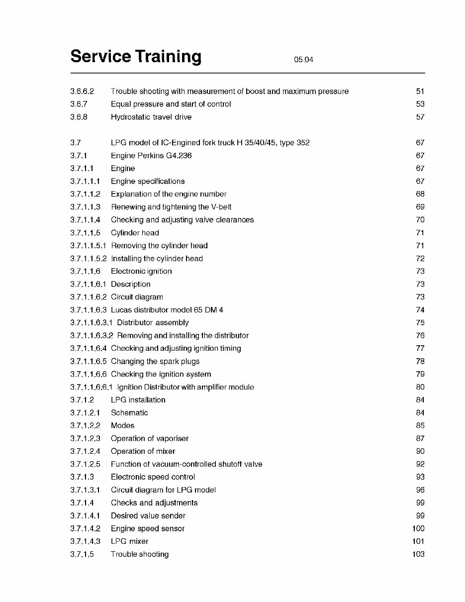
3.6.6.2 T rouble shooting with measurement of boost and maximum pressure 51
3.6.7 Equal pressure and start of control 53
3.6.8 Hydrostatic travel drive 57
3.7 LPG model of IC-Engined fork truck H 35/40/45, type 352 67
3.7.1 Engine Perkins G4.236 67
3.7.1.1 Engine 67
3,7.1.1.1 Engine specifications 67
3.7.1.1.2 Explanation of the engine number 68
3.7.1.1.3 Renewing and tightening the V-belt 69
3.7.1.1.4 Checking and adjusting valve clearances 70
3.7.1.1.5 Cylinder head 71
3.7.1.1.5.1 Removing the cylinder head 71
3.7.1.1.5.2 Installing the cylinder head 72
3.7.1.1.6 Electronic ignition 73
3.7.1.1.6.1 Description 73
3.7.1.1.6.2 Circuit diagram 73
3.7.1.1.6.3 Lucas distributor model 65 DM 4 74
3.7.1.1.6.3.1 Distributor assembly 75
3.7.1.1.6.3.2 Removing and installing the distributor 76
3.7.1.1.6.4 Checking and adjusting ignition timing 77
3.7.1.1.6.5 Changing the spark plugs 78
3.7.1.1.6.6 Checking the ignition system 79
3.7.1.1.6.6.1 Ignition Distributor with amplifier module 80
3.7.1.2 LPG installation 84
3.7.1.2.1 Schematic 84
3.7.1.2.2 Modes 85
3.7.1.2.3 Operation of vaporiser 87
3.7.1.2.4 Operation of mixer 90
3.7.1 .2.5 Function of vacuum-controlled shutoff valve 92
3.7.1.3 Electronic speed control 93
3.7.1.3.1 Circuit diagram for LPG model 96
3.7.1.4 Checks and adjustments 99
3.7.1.4.1 Desired value sender 99
3.7.1.4.2 Engine speed sensor 100
3.7.1.4.3 LPG mixer 101
3.7.1.5 Troubleshooting 103
05.04 Service Training
3.7.1.5.1 Circuit diagram for engine speed control 104
3.7.1.5.2 Electronic control device 106
3.7.2 Engine Perkins 1004-40 S 108
3.7.2.1 Engine 108
3.7.2.1.1 Engine specifications 108
3.7.2.1.2 Explanation of the engine number 109
3.7.2,1.3
Renewing and tightening the V-belt 110
3.7.2.1 .4 Adjusting the valve clearance 1 11
3.7.2.1 .4.1 Valve clearance adjustment schematic 112
3.7.2.1.5 Cylinder head 113
3.7.2.1.5.1 Removing the cylinder head 113
3.7.2.1.5.2 Installing the cylinder head 114
3.7.2.1.6 Electronic ignition 116
3.7.2.2 Electrical system 122
3.7.2.2.1 Main circuit diagram series 352 -03/ 04 122
3.7.2.2.2 Circuit diagram for options 125
3.7.2.2.3 Layout of electrical installation 131
3.7.2.3 LPG system 132
3.7.2.3.1 Without computer-controlled catalytic converter 132
3.7.2.3.2 With computer-controlled catalytic converter 133
3.7.2.3.3 Mixer 134
3.7.2.4 Electronic speed control 136
3.7.2.5 Troubleshooting 140
3.7.2.5.1 Circuit diagram for engine speed control 140
3.7.2.5.2 Electronic control device 142
3.7.2.5.3 Trouble shooting the transistorised ignition system 144
3.7.2.6 Mechanical ignition timing 153
3.8 Drive axle AH 45-02 for model H 35/40/45 D-04/T-04 1
3.8.1 Drive axle AH 45 -02 with hub reduction gearbox, disc brake and hydraulic motor 2
3.8.2 Repairing the reduction gearbox 4
3.8.2,1 Reduction gearbox assembly (planetary hub reduction gearbox) 4
3.8.2.2 Renewing radial seal ring of planetary hub reduction gearbox 5
3.8.2.3 Removal and installation of multiple disc brake and hydraulic motor and swashplate 8
You're Reading a Preview
What's Included?
Fast Download Speeds
Online & Offline Access
Access PDF Contents & Bookmarks
Full Search Facility
Print one or all pages of your manual
$42.99
Viewed 97 Times Today


Secure transaction
What's Included?
Fast Download Speeds
Online & Offline Access
Access PDF Contents & Bookmarks
Full Search Facility
Print one or all pages of your manual
$42.99
Get the Original Illustrated Service Training manual for Linde Forklift Truck with Diesel and LPG Engines 352 series. This manual covers models H35 D, H40 D, H45 D, H35 T, H40 T, H45 T, H35 D-02, H40 D-02, H45 D-02, H35 D-03, H40 D-03, H45 D-03, H35 T-03, H40 T-03, H45 T-03, H35 D-04, H40 D-04, H45 D-04, H35 T-04, H40 T-04, and H45 T-04.
Format: 232 pages
Language: English
Table of contents:
- 3.1 Engine
- 3.1.1 Engine specifications (Diesel)
- 3.1.2 Explanation of the engine number
- 3,1.3 Renewing and tightening the V-belt
- 3.1.4 Adjusting the valve clearance
- 3.1.4.1 Valve clearance adjustment schematic
- 3.1.5 Cylinder head
- 3.1.5.1 Removing the cylinder head
- 3.1.5.2 Installing the cylinder head
- 3.1.6 Engine timing and tightening torques
- 3.1.7 Injection nozzles
- 3.1.7.1 Removing and installing the injection nozzles, parts list AA 80247/AG 80757
- 3.1.7.2 Removing and installing the injection nozzles, parts list AP 80975
- 3.1.7.3 Repairing the injection nozzles
- 3.1.8 Fuel injection pump
- 3.1.8.1 Removing and installing the fuel injection pump, version with begin of delivery mark on pump flange
- 3.1.8.2 Removing and installing the fuel injection pump, version with adjusting pin (pin timing)
- 3.1.9 Fuel injection pump
- 3.1.10 Special tools
- 3.2 Hydrostatic transmission
- 3.2.1 Schematic diagram of the drive unit
- 3.2.2 Travel drive specifications
- 3.2.3 Hydraulic circuit schematic
- 3.2.3.1 Hydraulic circuit schematic Type 352 -03
- 3.2.4 Description of the hydrostatic travel drive
- 3.2.5 Flushing of the variable displacement pump and drive axle
- 3.2.6 Power limiter and anti stall device
- 3.2.7 Engine lock-out logic - reversing lock
- 3.2.8 Oil reservoir
- 3.2.9 Hydraulic remote control unit, HPV 130
- 3,2.10 Hydraulic remote control unit, HPV 135 -02
- 3.2.10,1 Valve adjustment on HPV 135 -02
- 3.3 Working hydraulic system
- 3.3.1 Circuit diagram of working hydraulic system
- 3.3.2 Description of the working hydraulic system
- 3.4 Wiring diagram
- 3.4.1 Wiring diagram for Diesel model
- 3.4.2 Wiring diagram for diesel model type 352 -03, standard equipment
- 3.4.3 Wiring diagram for diesel model type 352 -03, options
- 3.5 Checks and adjustments
- 3.5.1 Travel pedals
- 3.5.2 Brake pedal
- 3.5.3 Bowden cable for parking brake
- 3.5.4 Average wheel speed
- 3.5.5 Speed control for Diesel model
- 3.5.6 Start of drive wheel rotation
- 3.5.7 Brake shaft at travel control unit
- 3.5.8 Symmetry of the travel control
- 3.5.8.1 Drive wheel start of rotation
- 3.5.8.2 Engine speed increase
- 3.5.9 Pressure difference Ap
- 3.5.10 Reversing lock
- 3.5.1 1 Hydraulic neutral position
- 3.5.12 Sealing the wheel shaft
- 3.6 Troubleshooting
- 3.6.1 Line layout for trouble shooting
- 3.6.2 Aids and tools for measurements
- 3.6.3 Remarks to trouble shooting
- 3.6.4 Engine hydraulic speed control
- 3.6.4.1 Functional test
- 3.6.4.2 Troubleshooting
- 3.6.5 Hydraulic brake system
- 3.6.5.1 Functional test
- 3.6.5.2 Troubleshooting
- 3.6.6 Power assissted steering
- 3.6.6.1 Trouble shooting without measuring boost and maximum pressure
- 3.6.6.2 T rouble shooting with measurement of boost and maximum pressure
- 3.6.7 Equal pressure and start of control
- 3.6.8 Hydrostatic travel drive
- 3.7 LPG model of IC-Engined fork truck H 35/40/45, type 352
- 3.7.1 Engine Perkins G4.236
- 3.7.1.1 Engine
- 3.7.1.1.1 Engine specifications
- 3.7.1.1.2 Explanation of the engine number
- 3.7.1.1.3 Renewing and tightening the V-belt
- 3.7.1.1.4 Checking and adjusting valve clearances
- 3.7.1.1.5 Cylinder head
- 3.7.1.1.5.1 Removing the cylinder head
- 3.7.1.1.5.2 Installing the cylinder head
- 3.7.1.1.6 Electronic ignition
- 3.7.1.1.6.1 Description
- 3.7.1.1.6.2 Circuit diagram
- 3.7.1.1.6.3 Lucas distributor model 65 DM 4
- 3.7.1.1.6.3.1 Distributor assembly
- 3.7.1.1.6.3.2 Removing and installing the distributor
- 3.7.1.1.6.4 Checking and adjusting ignition timing
- 3.7.1.1.6.5 Changing the spark plugs
- 3.7.1.1.6.6 Checking the ignition system
- 3.7.1.1.6.6.1 Ignition Distributor with amplifier module
- 3.7.1.2 LPG installation
- 3.7.1.2.1 Schematic
- 3.7.1.2.2 Modes
- 3.7.1.2.3 Operation of vaporiser
- 3.7.1.2.4 Operation of mixer
- 3.7.1.2.5 Function of vacuum-controlled shutoff valve
- 3.7.1.3 Electronic speed control
- 3.7.1.3.1 Circuit diagram for LPG model
- 3.7.1.4 Checks and adjustments
- 3.7.1.4.1 Desired value sender
- 3.7.1.4.2 Engine speed sensor
- 3.7.1.4.3 LPG mixer
- 3.7.1.5 Troubleshooting
- 3.7.1.5.1 Circuit diagram for engine speed control
- 3.7.1.5.2 Electronic control device
- 3.7.2 Engine Perkins 1004-40 S
- 3.7.2.1 Engine
- 3.7.2.1.1 Engine specifications
- 3.7.2.1.2 Explanation of the engine number
- 3.7.2,1.3 Renewing and tightening the V-belt
- 3.7.2.1 Engine
- 3.7.1.1 Engine
- 3.7.1 Engine Perkins G4.236


