

Н»®Є·Ѕ» М®ї·І·І№
Мё· ј±Ѕ«і»І¬ · ±Іґ§ °®±Є·ј»ј є±® §±«® «» ј«®·І№ ¬®ї·І·І№ їІј ·¬ ®»ії·І ¬ё» »ЁЅґ«·Є» °®±°»®¬§ ±є
ФЧТЬЫ ЯЩ Й»®µ№®«°°» Ъґ«®є*®ј»®¦»«№» «Іј Ш§ј®ї«ґ·µ
Ф·Іј» Ыґ»Ѕ¬®·Ѕ Ъ±®µ М®«Ѕµ
Ы пм с пк с пкЭ с пи
Н»®·» ннл


Н»®Є·Ѕ» М®ї·І·І№
Рї№» п
Н»Ѕ¬·±І мтп
м ФЧТЬЫ ЫФЫЭМОЧЭ ЪСОХ МОЛЭХ Ы пм с пк с пкЭ с пиР МЗРЫ ннл
мтп ЬОЧКЫ у УСМСО
Мё» »ґ»Ѕ¬®·Ѕ є±®µ ¬®«Ѕµ ї®» °±©»®»ј ѕ§ ЬЭ »®·»у©±«Іј і±¬±®т ЬЭ »®·»у©±«Іј і±¬±® ј»Є»ґ±° ¬ё»
ё·№ё»¬ ¬±®Ї«» ±є їґґ »ґ»Ѕ¬®·Ѕ і±¬±®т ЧІ »®·»у©±«Іј і±¬±® ¬ё» є·»ґј ©·Іј·І№ · Ѕ±ІІ»Ѕ¬»ј ·І »®·» ¬± ¬ё»
ї®ії¬«®»т
Мё» є·»ґј ©·Іј·І№ ¬»®і·Іїґ Ьп їІј Ьо їІј ¬ё» ї®ії¬«®» ©·Іј·І№ ¬»®і·Іїґ Яп їІј Яо ї®» ії®µ»јт Мё»§
ї®» ґ»їј ±«¬ ±є ¬ё» і±¬±® »°ї®ї¬»ґ§т Мё» ¬®їЅ¬·±І і±¬±® ј·®»Ѕ¬·±І · ®»Є»®»ј ѕ§ ®»Є»®·І№ ¬ё» ї®ії¬«®»
є·»ґјт
Я °»»ј »І±® · ·І¬їґґ»ј ±І ¬ё» ®·№ё¬уёїІј ¬®їЅ¬·±І і±¬±® є±® »І·І№ ¬ё» і±¬±® °»»ј їІј »І» ±є
®±¬ї¬·±Іт
Т±¬»ж Ь«» ¬± ј·єє»®»І¬ ії¬ °·Є±¬ф ¬ё» ®·№ё¬у їІј ґ»є¬уёїІј ¬®їЅ¬·±І і±¬±® ї®» І±¬ ·ј»І¬·Ѕїґт
мтптп МОЯЭМЧСТ УСМСО
М§°»ж Ц«ґ·
К±ґ¬ї№»ж ми К
Р±©»®ж мтр µЙ Но шкр і·І ®ї¬·І№ч
М§°» ±є °®±¬»Ѕ¬·±Іж ЧРрр с оо
Ю®«ё ·¦»ж мр Ё но Ё пр іі
У·Іт ґ»І№¬ёж пн іі
Э±іі«¬ї¬±® ј·їі»¬»®ж І»© ин іі
Яјіт ®»©±®µ·І№ж ј±©І ¬± йи іі
ЫЇ«·°°»ј ©·¬ёж п ¬»і°»®ї¬«®» »І±®ф Ю®«ё і±І·¬±® ±І »їЅё і±¬±® ѕ®«ёф °»»ј »І±® ±І ОШ
і±¬±®
Н»®Є·Ѕ» М®ї·І·І№
Н»Ѕ¬·±І мтп
Рї№» о
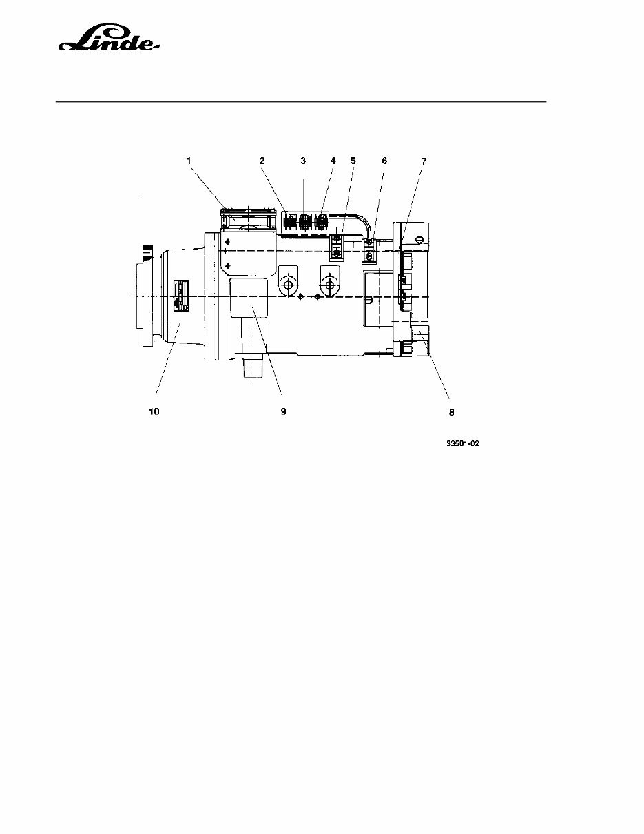
О·№ё¬уёїІј ¬®їЅ¬·±І і±¬±® пУп
п ЪїІ зУп
о Э±ІІ»Ѕ¬±® зИпрф єїІ
н Э±ІІ»Ѕ¬±® пИйф і±¬±®
м Э±ІІ»Ѕ¬±® пИптпф °»»ј »І±®
л Ъ·»ґј ¬»®і·Іїґ ЬоЬп
к Я®ії¬«®» ¬»®і·Іїґ ЯпЯо
й Н°»»ј »І±®
и Ю®їµ» ј·Ѕ
з Рґї¬·Ѕ ѕ®«ё Ѕ±Є»®
пр Щ»ї® ®»ј«Ѕ»®
Я®ії¬«®» ¬»®і·Іїґ Яп їІј Яо
Ъ·»ґј ¬»®і·Іїґ Ьп їІј Ьо
Э±ІІ»Ѕ¬±® пИй ±І ОШ ¬®їЅ¬·±І і±¬±® пУп
Ю®«ё ©·¬Ѕё кЮм
Ю®«ё ©·¬Ѕё кЮм
М»і°»®ї¬«®» »І±® кЮп
М»і°»®ї¬«®» »І±® кЮп
Э±ІІ»Ѕ¬±® пИи ±І ФШ ¬®їЅ¬·±І і±¬±® пУо
Ю®«ё ©·¬Ѕё кЮл
Ю®«ё ©·¬Ѕё кЮл
М»і°»®ї¬«®» »І±® кЮо
М»і°»®ї¬«®» »І±® кЮо
Н»®Є·Ѕ» М®ї·І·І№
Рї№» н
Н»Ѕ¬·±І мтп
мтпто ЭШЫЭХЧТЩ ЯТЬ ОЫТЫЙЧТЩ МШЫ МОЯЭМЧСТ УСМСО ЮОЛНШЫН
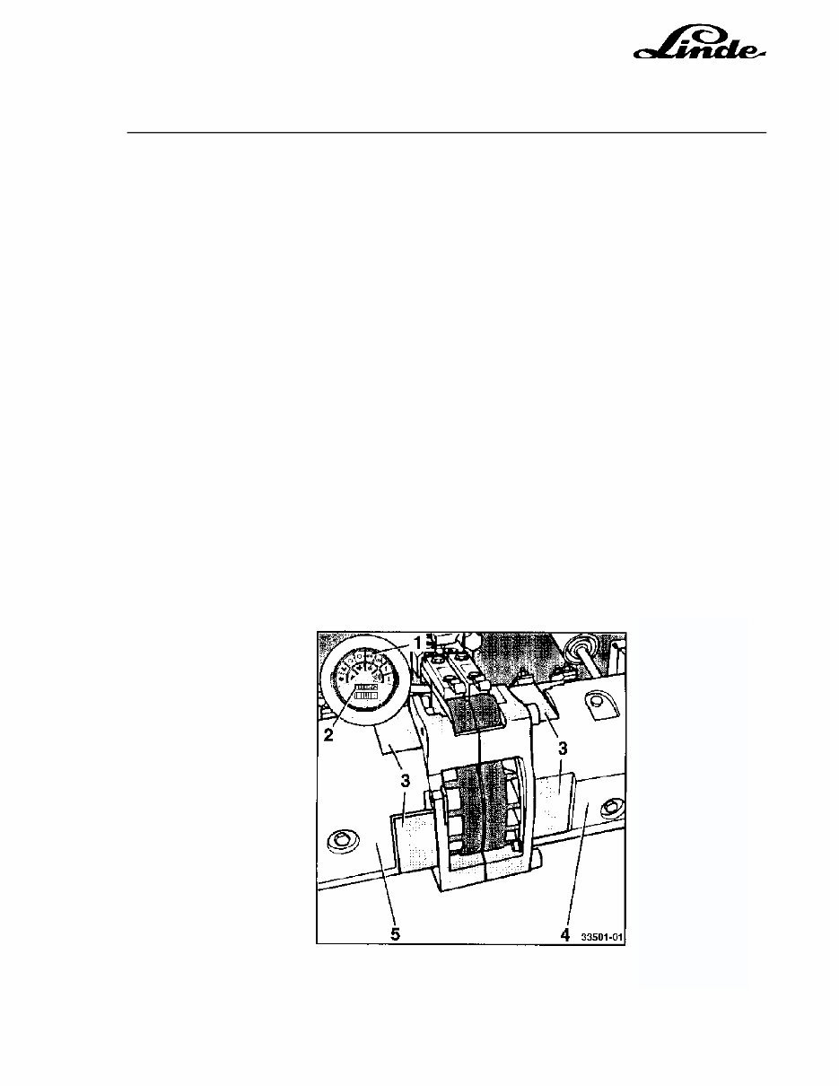
Мё» і±¬±® ѕ®«ё» ЅїІ ѕ» Ѕё»Ѕµ»ј є±® ©»ї® їІј є®»» і±Є»і»І¬ їє¬»® ±°»І·І№ ¬ё» ј®·Є»®Ћ ±Є»®ё»їј
№«ї®јт Мё» ®»Ї«·®»ј ®»І»©їґ ±є ¬ё» і±¬±® ѕ®«ё» · їґ± ·Іј·Ѕї¬»ј ѕ§ ¬ё» ·Іј·Ѕї¬±® ґїі° шпч ·ґґ«і·Ії¬·І№
·І ¬ё» Ѕ±і°±·¬» ·І¬®«і»І¬т Мё» І«іѕ»® ±є ¬ё» і±¬±® ·І Ї«»¬·±І шп г ОШ і±¬±®ф о г ФШ і±¬±®ч ї°°»ї®
·І ¬ё» ФЭЬ ј·°ґї§ шочт
у Юґ±Ѕµ «° ¬ё» ¬®«Ѕµ ї¬ ¬ё» їЁґ»т
у Ої·» ¬ё» є±®µ Ѕї®®·ї№» їІј »Ѕ«®» ї№ї·І¬ ·ІїјЄ»®¬»І¬ ґ±©»®·І№т
у Эё±Ѕµ ¬ё» ©ё»»ґ
у М«®І ±єє ¬ё» µ»§ ©·¬Ѕёт
у Ь·Ѕ±ІІ»Ѕ¬ ¬ё» ѕї¬¬»®§ °ґ«№т
у С°»І ¬ё» ±Є»®ё»їј №«ї®ј ї єї® ї ¬ё» »Ѕ±Іј ј»¬»І¬ °±·¬·±Іт
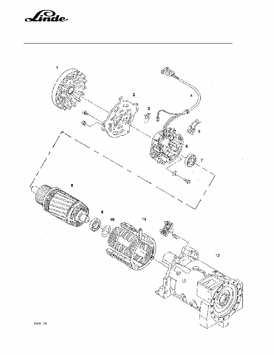
у О»і±Є» ¬ё» ѕ®«ё Ѕ±Є»® шнч ±І ¬ё» ¬®їЅ¬·±І і±¬±® шмч їІј шлчт
у Ф·є¬ ¬ё» ѕ®«ё °®·І№ шйчт
ТСМЫж Йё»І ґ·є¬·І№ ¬ё» °®·І№ є®±і ¬ё» і±¬±® ѕ®«ё» їІј °«¬¬·І№ ¬ё»і ±І ¬ё» ё±ґј»®ф ѕ» «®» ¬ёї¬
¬ё»§ ј± І±¬ ґ·ј» ±єє їІј ±°»Іф ї Ѕ±і°®»·І№ ¬ё»і ©ё»І ¬ё» і±¬±® ї®» ·І¬їґґ»ј ·
»Ё¬®»і»ґ§ ј·єє·Ѕ«ґ¬
у Р«ґґ ¬ё» ѕ®«ё» шич ±«¬ ±є ¬ё» №«·ј» ші·І·і«і ґ»І№¬ё пн ііч
у Эё»Ѕµ ¬ё» ґ»І№¬ё ±є ¬ё» і±¬±® ѕ®«ё» ші·І·і«і ґ»І№¬ё пн іічт
у О»І»© ©±®І і±¬±® ѕ®«ё» ±Іґ§ ї ї »¬т
у Яє¬»® ®»І»©·І№ ¬ё» ѕ®«ё»ф Ѕё»Ѕµ ¬ё» ѕ®«ё» є±® є®»» і±Є»і»І¬ ·І ¬ё» №«·ј» їІј ¬ё» ѕ®«ё ґ»їј є±®
»Ѕ«®·¬§т
у О»у·І¬їґґ ¬ё» ѕ®«ё Ѕ±Є»® шнчт
Н»®Є·Ѕ» М®ї·І·І№
Н»Ѕ¬·±І мтп
Рї№» м
мтптн МОЯЭМЧСТ УСМСО ЬЧНЯННЫУЮФЗ
You're Reading a Preview
What's Included?
 Lifetime Access
Fast Download Speeds
Online & Offline Access
Access PDF Contents & Bookmarks
Full Search Facility
Print one or all pages of your manual
$37.99
Linde Electric Fork Truck 335 series: E14, E16, E16C, E18 Service Training Manual
Viewed 89 Times Today

What's Included?
Lifetime Access
Fast Download Speeds
Online & Offline Access
Access PDF Contents & Bookmarks
Full Search Facility
Print one or all pages of your manual
$37.99

Secure transaction
What's Included?
Lifetime Access
Fast Download Speeds
Online & Offline Access
Access PDF Contents & Bookmarks
Full Search Facility
Print one or all pages of your manual
Description
Illustrated Factory Service Training Manual For Linde Electric ForkLift Truck 335 series is a comprehensive source of information for professionals and DIY enthusiasts alike. This manual covers models E14, E16, E16C, and E18, and includes 146 pages of detailed content in English.
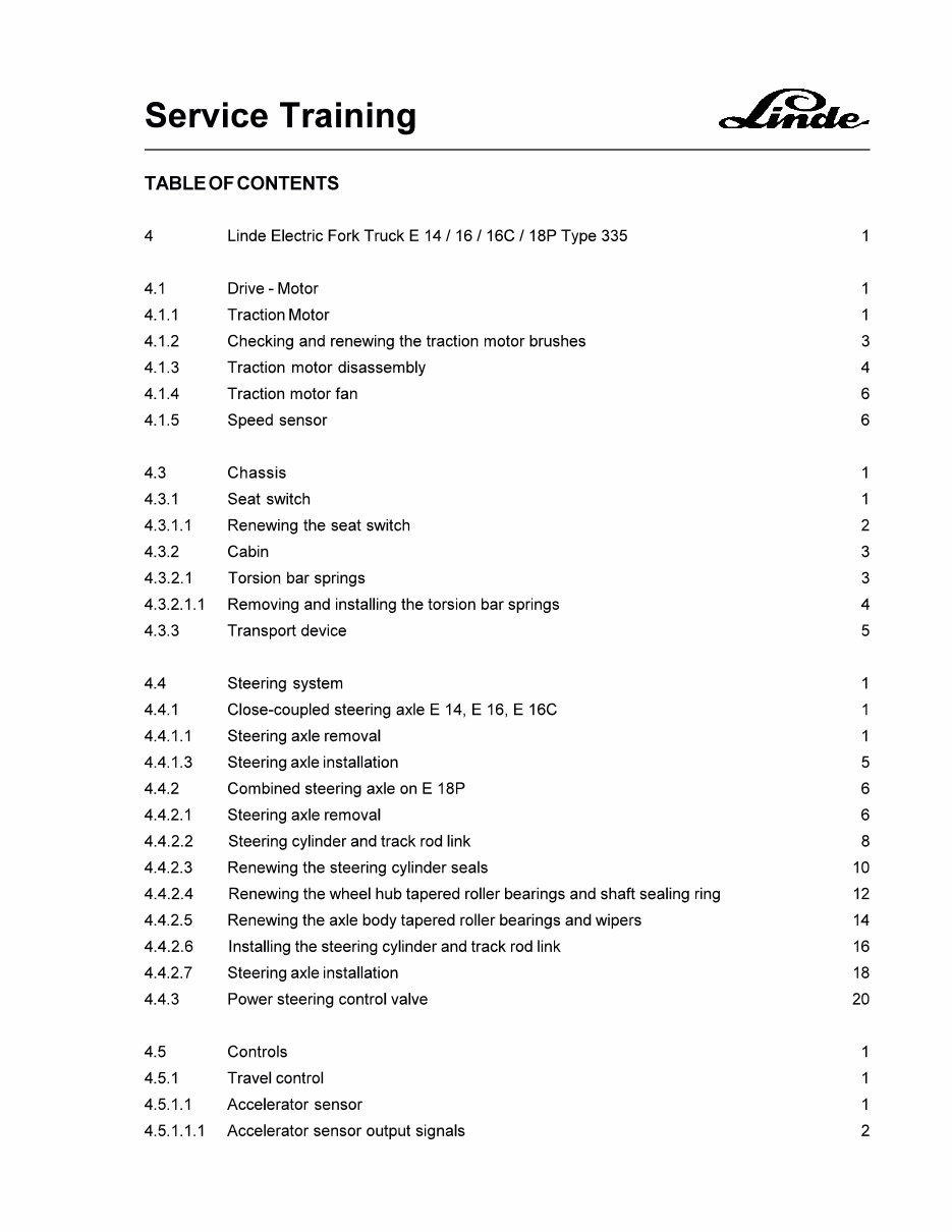
- Drive-Motor
- Traction Motor
- Checking and renewing the traction motor brushes
- Traction motor disassembly
- Traction motor fan
- Speed sensor
- Chassis
- Seat switch
- Renewing the seat switch
- Cabin
- Torsion bar springs
- Removing and installing the torsion bar springs
- Torsion bar springs
- Transport device
- Seat switch
- Steering system
- Close-coupled steering axle E 14, E 16, E 16C
- Steering axle removal
- Steering axle installation
- Combined steering axle on E18P
- Steering axle removal
- Steering cylinder and track rod link
- Renewing the steering cylinder seals
- Renewing the wheel hub tapered roller bearings and shaft sealing ring
- Renewing the axle body tapered roller bearings and wipers
- Installing the steering cylinder and track rod link
- Steering axle installation
- Power steering control valve
- Close-coupled steering axle E 14, E 16, E 16C
- Controls
- Travel control
- Accelerator sensor
- Accelerator sensor output signals
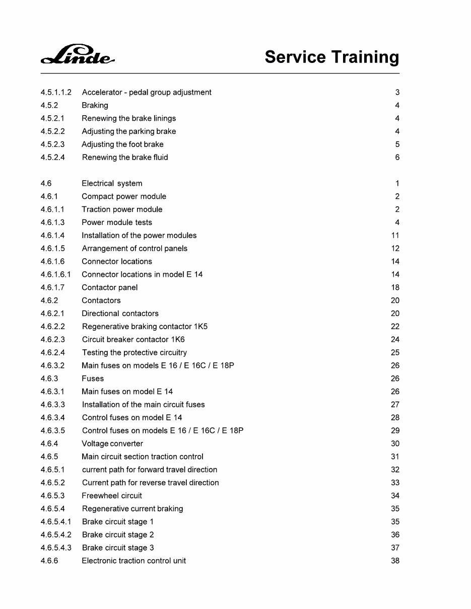
- Accelerator - pedal group adjustment
- Accelerator sensor
- Braking
- Renewing the brake lining
- Adjusting the parking brake
- Adjusting the foot brake
- Renewing the brake fluid
- Travel control
- Electrical system
- Compact power module
- Traction power module
- Power module tests
- Installation of the power modules
- Arrangement of control panels
- Connector locations
- Connector locations in model E 14
- Contactor panel
- Contactors
- Directional contactors
- Regenerative braking contactor 1K5
- Circuit breaker contactor 1K6
- Testing the protective circuitry
- Fuses
- Main fuses on model E 14
- Main fuses on models E 16 / E 16C / E 18P
- Installation of the main circuit fuses
- Control fuses on model E 14
- Control fuses on models E 16 / E 16C / E 18P
- Voltage converter
- Main circuit section traction control
- Current path for forward travel direction
- Current path for reverse travel direction
- Freewheel circuit
- Regenerative current braking
- Brake circuit stage 1
- Brake circuit stage 2
- Brake circuit stage 3
- Electronic traction control unit
- Power supply
- Travel enable from seat switch and overhead guard switch
- Control of directional contactors
- Forward direction of travel
- Reverse direction of travel
- Single Pedal Models
- Modification to single pedal model
- Turning
- Turning with E 14/E 16/E 16C close-coupled steering
- Turning with combined axle model E 18P
- Sensors for steering position
- Handbrake current
- Checking the maximum current and handbrake current
- Temperature sensor for temperature monitoring of the traction motors
- Temperature sensor test
- Speed reduction
- Regenerative braking
- Speed sensor in the traction motor
- Current sensor
- LTM control for working hydraulic system and steering
- Electronic lift control
- Power supply
- Enable signal, thermal sensor and cut-out with discharged battery
- Control of the various work functions
- Adjustments
- Control of the steering function
- Operation of speed sensor 2B8
- Electronic lift control
- Fans
- Combined instrument
- Indicator lights
- Field weakening active indicator light (option)
- Turn signal indicator light
- Parking brake warning light
- Brake shoe warning light (option)
- Motor brush warning light
- Engine temperature warning light
- Travel direction indicator (option)
- Hydraulic oil temperature warning light (option)
- Hydraulic oil level warning light (option)
- Fan warning light
- Service interval indicator light
- Battery discharge indicator
- Indicator lights
- Linde Diagnostic Unit
- Operation of the diagnostic unit in connection with the combined instrument
- Programming of menu functions 11 to 24
- Resetting the service interval indicator with menu function 31
- Programming and reading the service hour menu functions 32 to 35
- Read-out functions with menu functions 41 to 43
- Brush monitoring
- Traction motor switching contacts
- Working hydraulics pump motor switching contacts
- Wiring diagram
- Compact power module
- Hydraulic system
- Hydraulic pump motor
- Renewing the hydraulic pump motor brushes
- Removing the hydraulic pump unit
- Control valve
- Removing the control valve
- Adjusting the pressure relieve valve2
- Distance sensor
- Working and steering hydraulics circuit diagram
- Tilt cylinder
- Tilt cylinder removal
- Sealing the tilt cylinder
- Adjusting the tilt angle
This manual, consisting of 146 pages in English, provides in-depth insights into the various components and systems of Linde Electric ForkLift Truck 335 series, making it an invaluable resource for maintenance and repair tasks.


