tllNGHEINRICH EFG-DF/dc 13-20 12.07 0.1 (GB) CHAPTERS - OVERVIEW Operating Instructions 1 9 Component Technical Description 2 10 General Truck Data Test and Setting Values 3 11 Truck - Maintenance 4 12 Service Manual Items 5 CAN Bus Control MP 1514F/H and MP 1502L 6 Electrical Wiring Diagrams 7 Hydraulic Wiring Diagrams 8
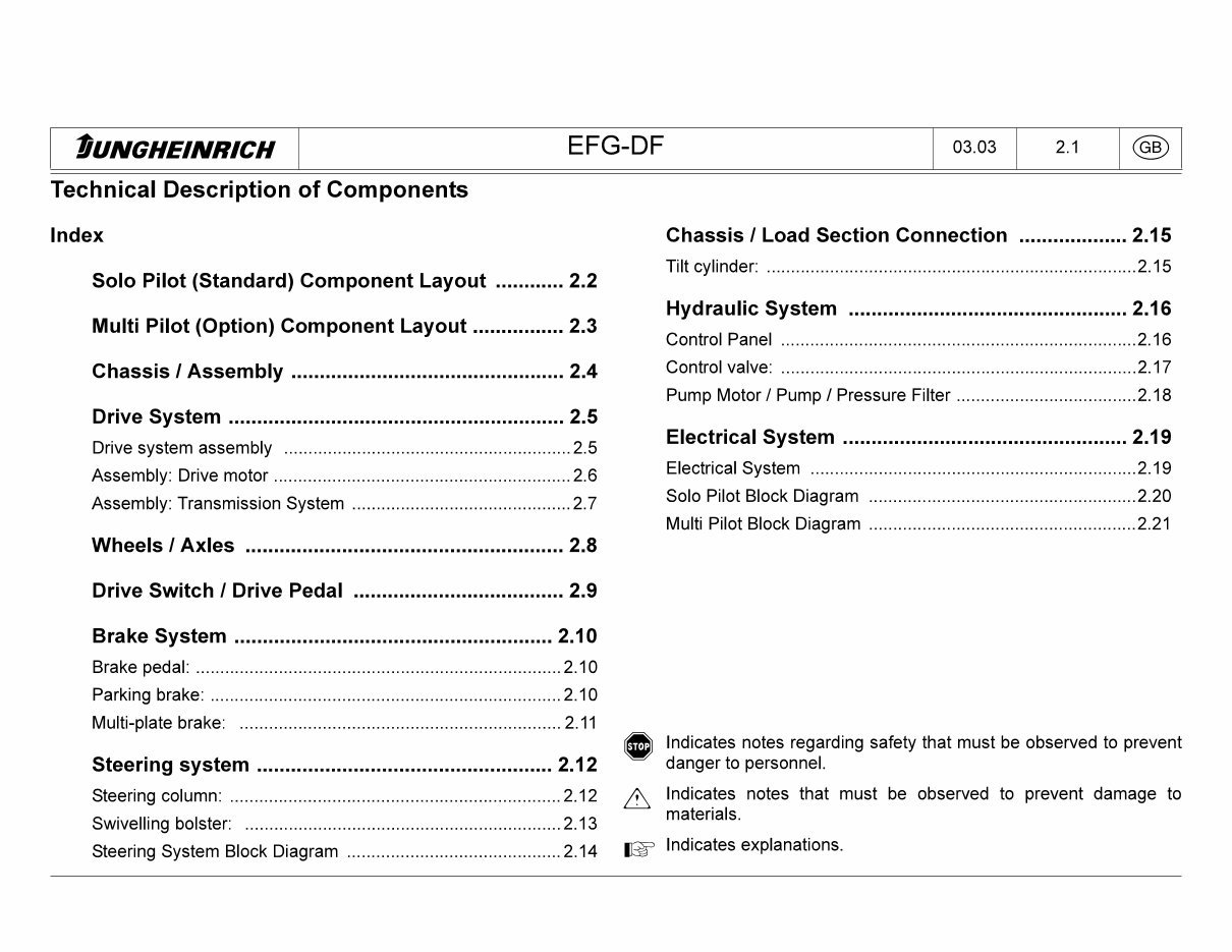
tUNGHEINRICH EFG-DF 03.03 2.1 (GB) Technical Description of Components Index Solo Pilot (Standard) Component Layout Multi Pilot (Option) Component Layout .... Chassis I Assembly Drive System Drive system assembly Assembly: Drive motor Assembly: Transmission System Wheels I Axles Drive Switch I Drive Pedal Brake System Brake pedal: Parking brake: Multi-plate brake: 2.2 2.3 2.4 2.5 ..2.5 .2.6 .2.7 2.8 2.9 2.10 ..2.10 ..2.10 ..2.11 Steering system Steering column: Swivelling bolster: Steering System Block Diagram 2.12 ..2.12 ..2.13 ..2.14 Chassis I Load Section Connection 2.15 Tilt cylinder: 2.15 Hydraulic System 2.16 Control Panel 2.16 Control valve: 2.17 Pump Motor / Pump / Pressure Filter 2.18 Electrical System 2.19 Electrical System 2.19 Solo Pilot Block Diagram 2.20 Multi Pilot Block Diagram 2.21 (®) Indicates notes regarding safety that must be observed to prevent danger to personnel. Indicates notes that must be observed to prevent damage to materials. jgp Indicates explanations.
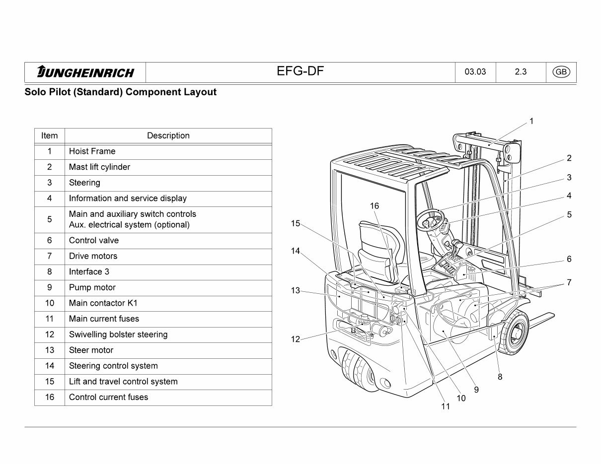
tUNGHEINRICH EFG-DF 03.03 2.3 (GB) Solo Pilot (Standard) Component Layout Item Description 1 Hoist Frame 2 Mast lift cylinder 3 Steering 4 Information and service display 5 Main and auxiliary switch controls Aux. electrical system (optional) 6 Control valve 7 Drive motors 8 Interface 3 9 Pump motor 10 Main contactor K1 11 Main current fuses 12 Swivelling bolster steering 13 Steer motor 14 Steering control system 15 Lift and travel control system 16 Control current fuses 11
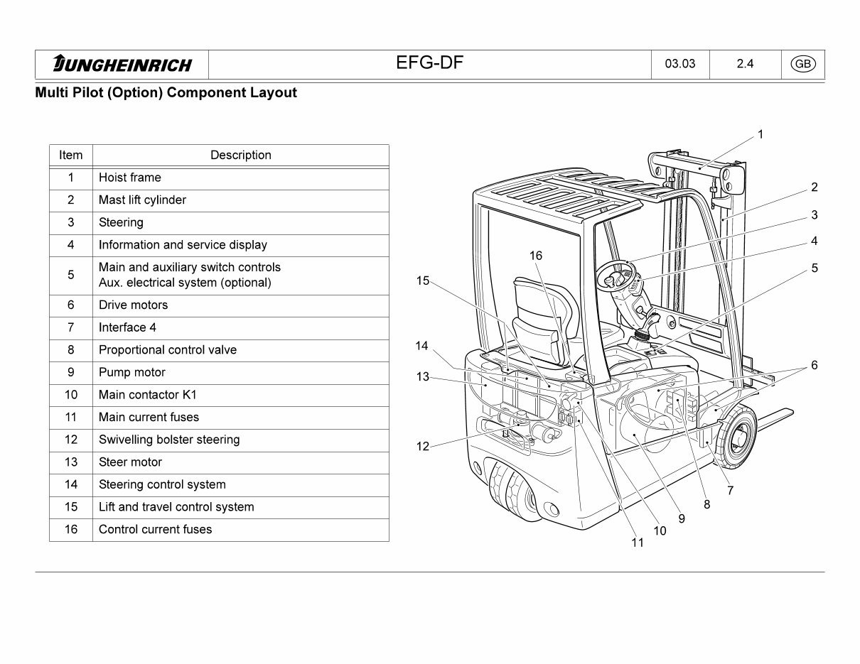
tUNGHEINRICH EFG-DF 03.03 2.4 <GB) Multi Pilot (Option) Component Layout Item Description 1 Hoist frame 2 Mast lift cylinder 3 Steering 4 Information and service display 5 Main and auxiliary switch controls Aux. electrical system (optional) 6 Drive motors 7 Interface 4 8 Proportional control valve 9 Pump motor 10 Main contactor K1 11 Main current fuses 12 Swivelling bolster steering 13 Steer motor 14 Steering control system 15 Lift and travel control system 16 Control current fuses
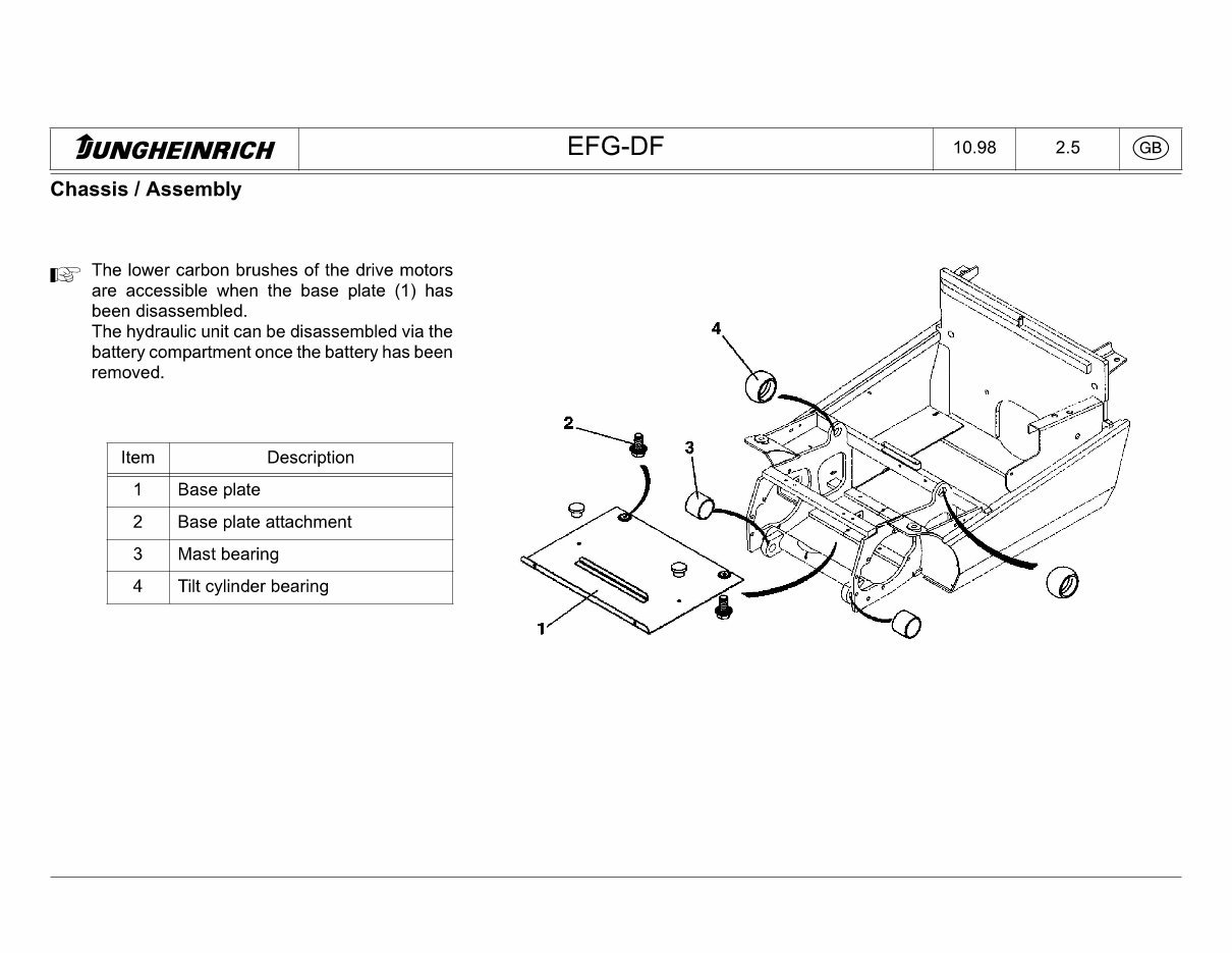
tUNGHEINRICH EFG-DF 10.98 2.5 (GB) Chassis I Assembly |gp The lower carbon brushes of the drive motors are accessible when the base plate (1) has been disassembled. The hydraulic unit can be disassembled via the battery compartment once the battery has been removed. Item Description 1 Base plate 2 Base plate attachment 3 Mast bearing 4 Tilt cylinder bearing
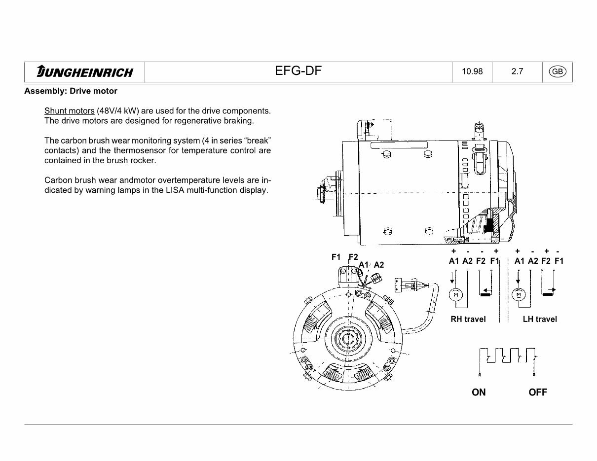
tUNGHEINRICH EFG-DF 10.98 2.7 dD Assembly: Drive motor Shunt motors (48V/4 kW) are used for the drive components. The drive motors are designed for regenerative braking. The carbon brush wear monitoring system (4 in series "break" contacts) and the thermosensor for temperature control are contained in the brush rocker. Carbon brush wear andmotor overtemperature levels are in¬ dicated by warning lamps in the LISA multi-function display. F1 ,F2 A1 A2 F2 F1 A1 A2 J RH travel + + - + - A1 A2 F2 F1 LH travel ON OFF
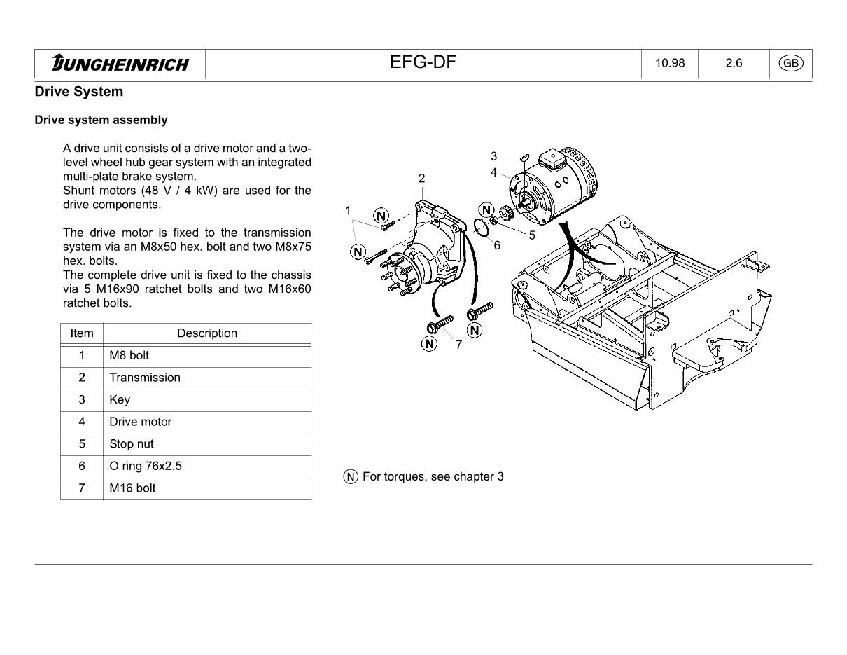
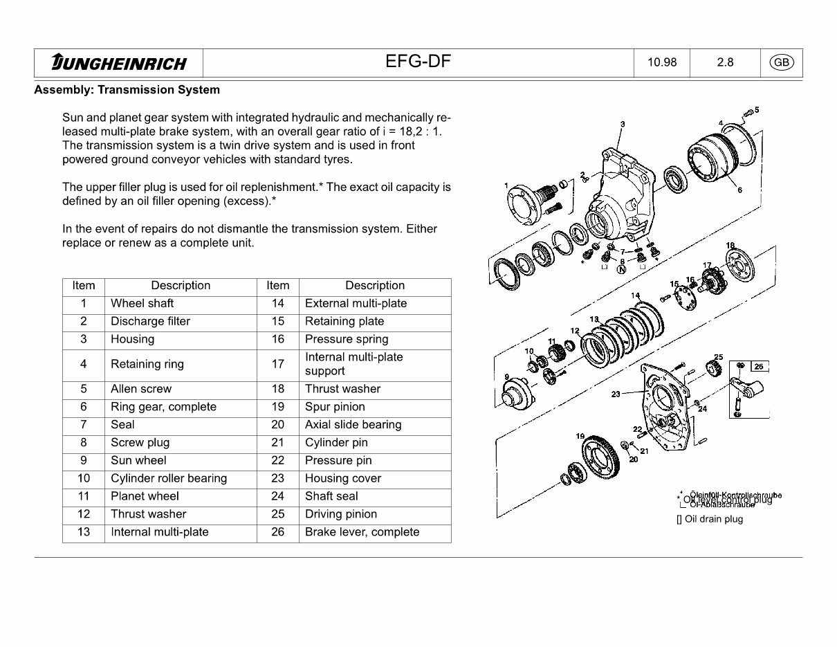
tUNGHEINRICH EFG-DF 10.98 2.8 Assembly: Transmission System Sun and planet gear system with integrated hydraulic and mechanically re¬ leased multi-plate brake system, with an overall gear ratio of i = 18,2 : 1. The transmission system is a twin drive system and is used in front powered ground conveyor vehicles with standard tyres. The upper filler plug is used for oil replenishment.* The exact oil capacity is defined by an oil filler opening (excess).* In the event of repairs do not dismantle the transmission system. Either replace or renew as a complete unit. Item Description Item Description 1 Wheel shaft 14 External multi-plate 2 Discharge filter 15 Retaining plate 3 Housing 16 Pressure spring 4 Retaining ring 17 Internal multi-plate support 5 Allen screw 18 Thrust washer 6 Ring gear, complete 19 Spur pinion 7 Seal 20 Axial slide bearing 8 Screw plug 21 Cylinder pin 9 Sun wheel 22 Pressure pin 10 Cylinder roller bearing 23 Housing cover 11 Planet wheel 24 Shaft seal 12 Thrust washer 25 Driving pinion 13 Internal multi-plate 26 Brake lever, complete [] Oil drain plug
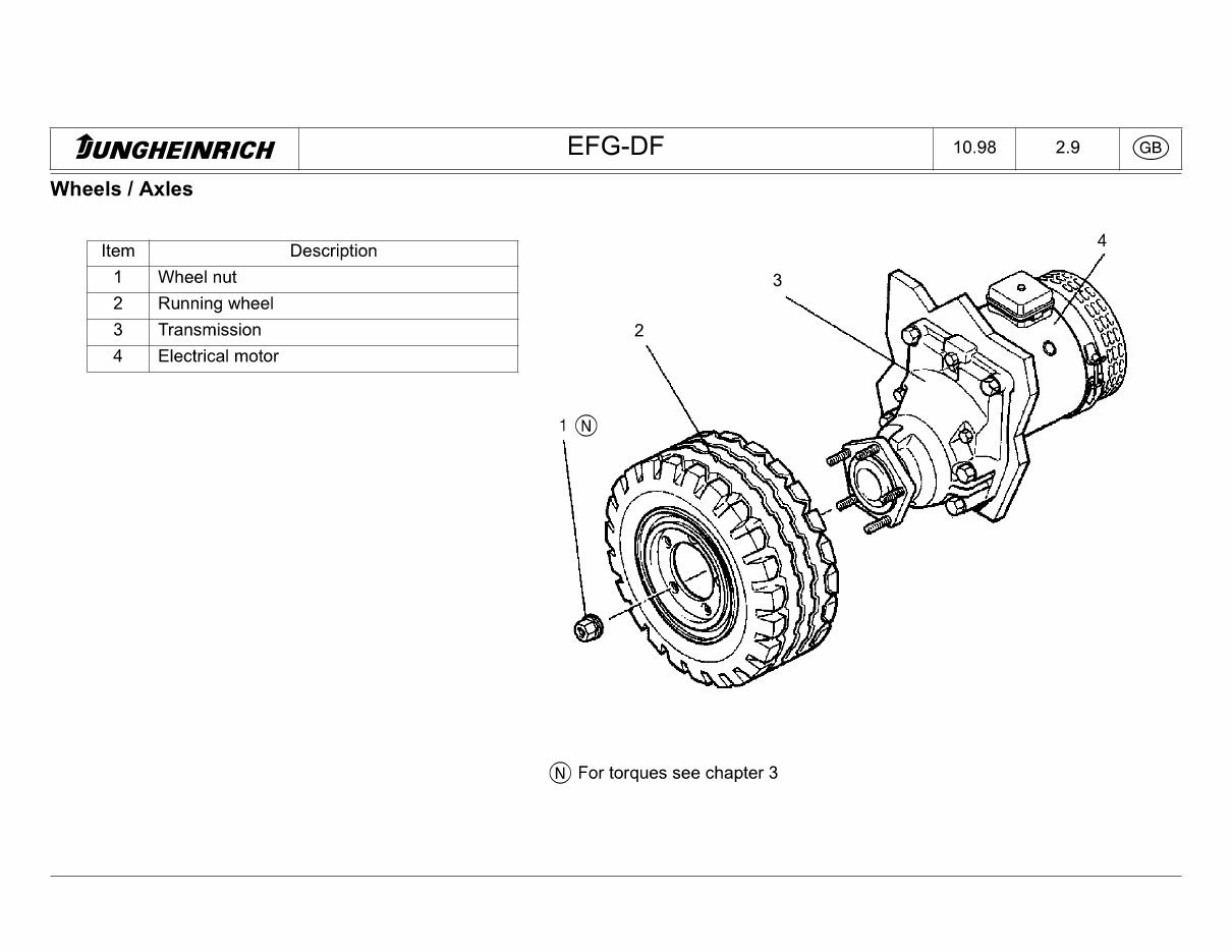
tUNGHEINRICH EFG-DF 10.98 2.9 (GB) Wheels I Axles Description Wheel nut Running wheel Transmission Electrical motor (n) For torques see chapter 3
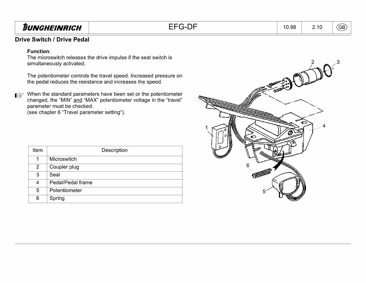
tUNGHEINRICH EFG-DF 10.98 2.10 Drive Switch I Drive Pedal Function: The microswitch releases the drive impulse if the seat switch is simultaneously activated. The potentiometer controls the travel speed. Increased pressure on the pedal reduces the resistance and increases the speed. I2P When the standard parameters have been set or the potentiometer changed, the "MIN" and "MAX" potentiometer voltage in the "travel" parameter must be checked. (see chapter 6 "Travel parameter setting"). Item Description 1 Microswitch 2 Coupler plug 3 Seal 4 Pedal/Pedal frame 5 Potentiometer 6 Spring
Get your hands on the Original Illustrated Factory Workshop Service Manual for Jungheinrich Electric Lift Truck Type EFG DFac. This manual is a comprehensive resource for both professional mechanics and DIY enthusiasts, providing high-quality images, circuit diagrams, and detailed instructions for operating and repairing your truck.
Containing 333 pages of valuable information, this manual covers the following models:
EFG DFac 13 (12.2003-01.2004)
EFG DFac 15 (12.2003-01.2004)
EFG DFac 16 (12.2003-01.2004)
EFG DFac 16L (12.2003-01.2004)
EFG DFac 18 (12.2003-01.2004)
EFG DFac 18L (12.2003-01.2004)
EFG DFac 20 (12.2003-01.2004)
This manual is available in English and includes a wide range of contents such as operating instructions, component technical descriptions, chassis and assembly details, drive system information, brake system instructions, steering system details, hydraulic system insights, electrical system guidance, general truck data, maintenance procedures, service manual items, and various diagrams including electrical and hydraulic wiring diagrams.