

tUNGHEINRICH EFG 2xx / 3xx
03.12 0.1 (S§)
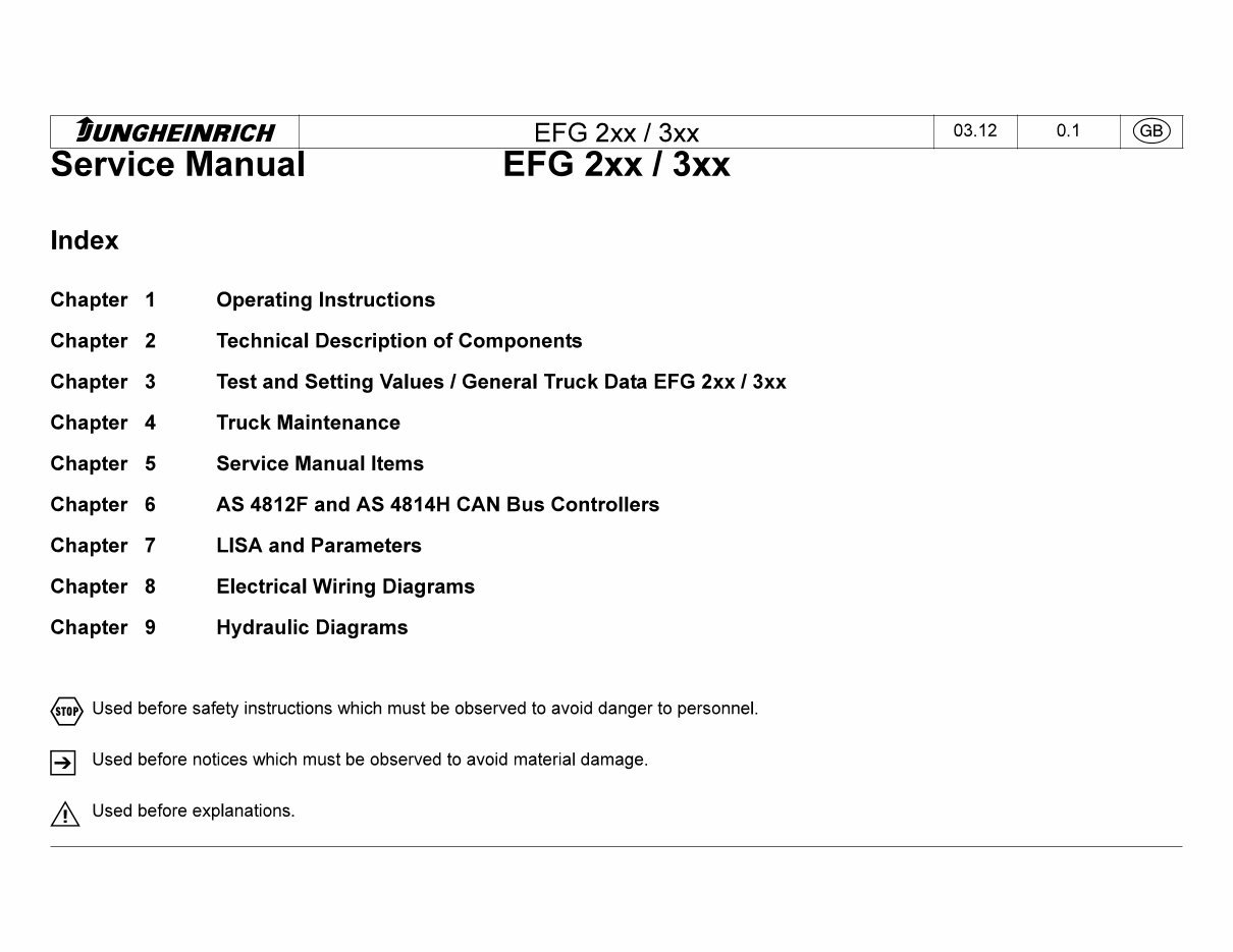
Service Manual EFG 2xx 13xx
Index
Chapter 1 Operating Instructions
Chapter 2 Technical Description of Components
Chapter 3 Test and Setting Values / General Truck Data EFG 2xx / 3xx
Chapter 4 Truck Maintenance
Chapter 5 Service Manual Items
Chapter 6 AS 4812F and AS 4814H CAN Bus Controllers
Chapter 7 LISA and Parameters
Chapter 8 Electrical Wiring Diagrams
Chapter 9 Hydraulic Diagrams
Used before safety instructions which must be observed to avoid danger to personnel.
S
Used before notices which must be observed to avoid material damage.
Used before explanations.
tUNGHEINRICH EFG 2xx / 3xx
05.04 1.1 (SB)
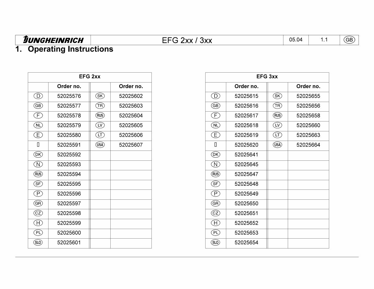
1. Operating Instructions
EFG 2xx
Order no. Order no.
CD
52025576
©
52025602
(GB)
52025577
<TR)
52025603
CD
52025578
(RUS)
52025604
<NL)
52025579
©
52025605
CD
52025580
©
52025606
ÿ
52025591
(USA)
52025607
(DK)
52025592
CD
52025593
(RUS)
52025594
©
52025595
CD
52025596
(GR)
52025597
©
52025598
CD
52025599
(PL)
52025600
©
52025601
EFG 3xx
Order no. Order no.
©
52025615
©
52025655
(GB)
52025616
(TR)
52025656
©
52025617
(RUS)
52025658
©
52025618
®
52025660
©
52025619
©
52025663
0 52025620
(USA)
52025664
(DK)
52025641
©
52025645
(RUS)
52025647
©
52025648
©
52025649
(GR)
52025650
©
52025651
©
52025652
(PL)
52025653
©
52025654
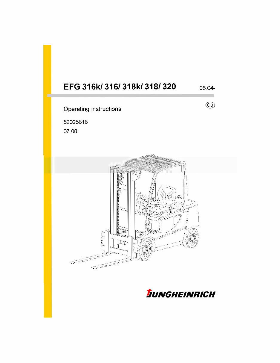
EFG 316k/ 316/318k/ 3181320
08. 04-
Operating instructions
52025616
07.08
Dungheinrich
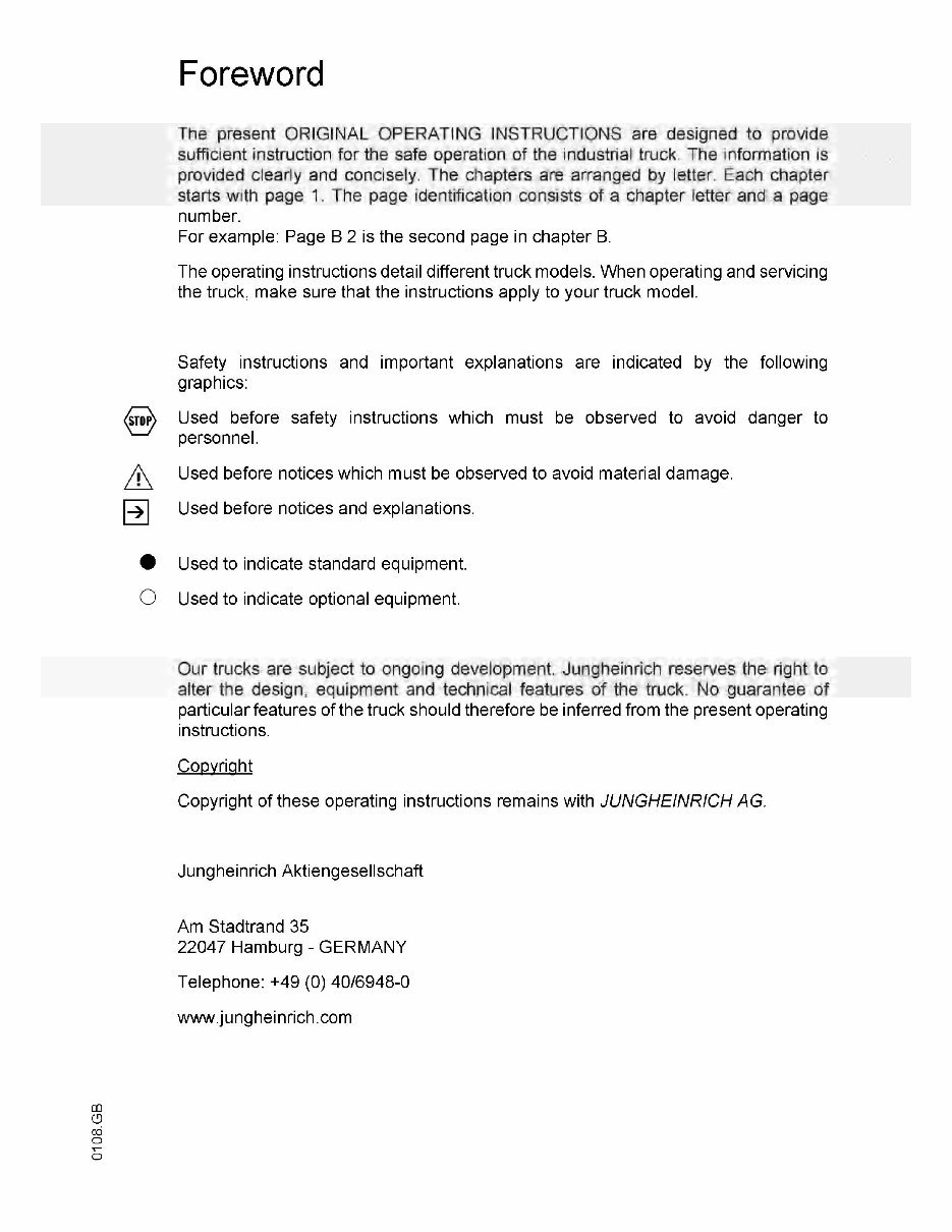
Foreword
The present ORIGINAL OPERATING INSTRUCTIONS are designed to provide
sufficient instruction for the safe operation of the industrial truck. The information is
provided clearly and concisely. The chapters are arranged by letter. Each chapter
starts with page 1. The page identification consists of a chapter letter and a page
number.
For example: Page B 2 is the second page in chapter B.
The operating instructions detail different truck models. When operating and servicing
the truck, make sure that the instructions apply to your truck model.
Safety instructions and important explanations are indicated by the following
graphics:
Used before safety instructions which must be observed to avoid danger to
personnel.
Used before notices which must be observed to avoid material damage.
Used before notices and explanations.
•
Used to indicate standard equipment.
O Used to indicate optional equipment.
Our trucks are subject to ongoing development. Jungheinrich reserves the right to
alter the design, equipment and technical features of the truck. No guarantee of
particular features of the truck should therefore be inferred from the present operating
instructions.
Copyright
Copyright of these operating instructions remains with JUNGHEINRICH AG.
Jungheinrich Aktiengesellschaft
Am Stadtrand 35
22047 Hamburg - GERMANY
Telephone: +49 (0) 40/6948-0
www.jungheinrich.com
CD
CD
CO
o
o
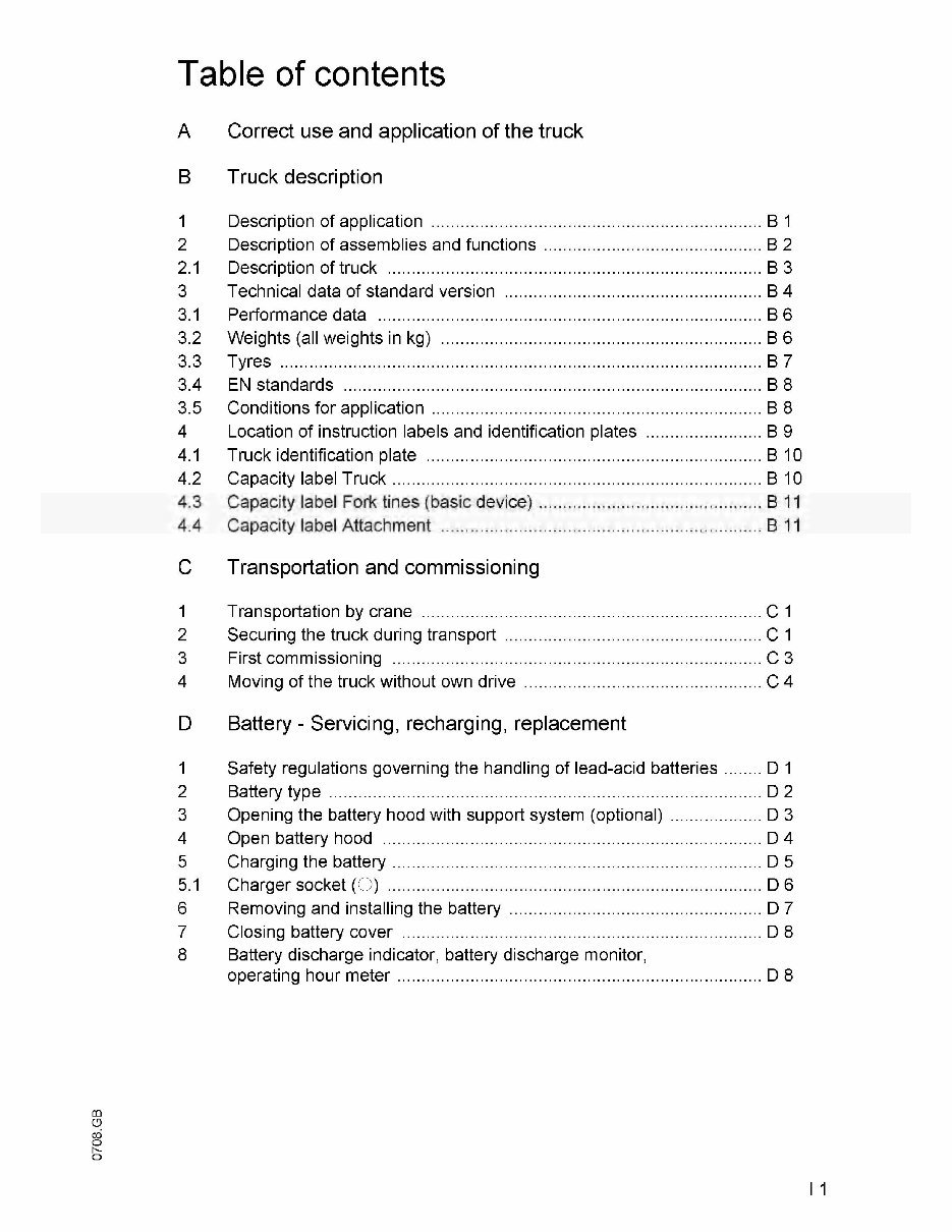
Table of contents
A Correct use and application of the truck
B Truck description
1 Description of application B1
2 Description of assemblies and functions B 2
2.1 Description of truck B 3
3 Technical data of standard version B4
3.1 Performance data B6
3.2 Weights (all weights in kg) B 6
3.3 Tyres B 7
3.4 EN standards B 8
3.5 Conditions for application B 8
4 Location of instruction labels and identification plates B 9
4.1 Truck identification plate B 10
4.2 Capacity label Truck B 10
4.3 Capacity label Fork tines (basic device) B 11
4.4 Capacity label Attachment B 1 1
C Transportation and commissioning
1 Transportation by crane C 1
2 Securing the truck during transport C 1
3 First commissioning C3
4 Moving of the truck without own drive C 4
D Battery - Servicing, recharging, replacement
1 Safety regulations governing the handling of lead-acid batteries D 1
2 Battery type D 2
3 Opening the battery hood with support system (optional) D 3
4 Open battery hood D 4
5 Charging the battery D 5
5.1 Charger socket (O) D 6
6 Removing and installing the battery D 7
7 Closing battery cover D 8
8 Battery discharge indicator, battery discharge monitor,
operating hour meter D 8
h-
O
I 1
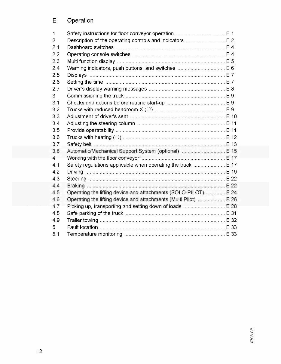
E Operation
1 Safety instructions for floor conveyor operation E 1
2 Description of the operating controls and indicators E 2
2.1 Dashboard switches E 4
2.2 Operating console switches E 4
2.3 Multi function display E 5
2.4 Warning indicators, push buttons, and switches E 6
2.5 Displays E 7
2.6 Setting the time E 7
2.7 Driver's display warning messages E 8
3 Commissioning the truck E 9
3.1 Checks and actions before routine start-up E 9
3.2 Trucks with reduced headroom X (O) E 9
3.3 Adjustment of driver's seat E 10
3.4 Adjusting the steering column E 11
3.5 Provide operatability E 1 1
3.6 Trucks with heating (O) E 12
3.7 Safety belt E 13
3.8 Automatic/Mechanical Support System (optional) E 15
4 Working with the floor conveyor E 17
4.1 Safety regulations applicable when operating the truck E 17
4.2 Driving E 19
4.3 Steering E 22
4.4 Braking E 22
4 5 Operating the lifting device and attachments (SOLO-PILOT) E 24
4.6 Operating the lifting device and attachments (Multi Pilot) E 26
4.7 Picking up, transporting and setting down of loads E 28
4.8 Safe parking of the truck E 31
4.9 Trailer towing E 32
5 Fault location E 33
5.1 Temperature monitoring E 33
m
O
cd
o
h-
o
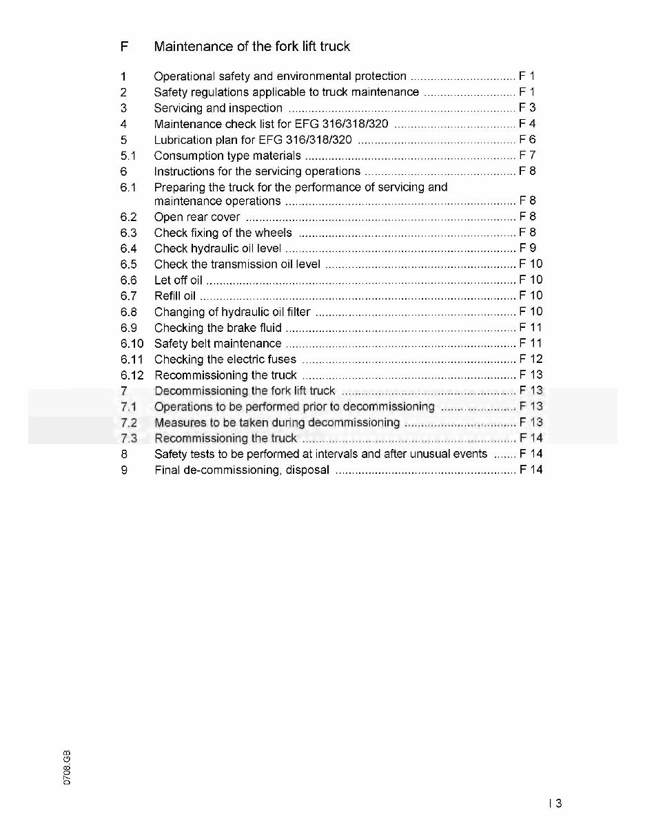
F Maintenance of the fork lift truck
1 Operational safety and environmental protection F 1
2 Safety regulations applicable to truck maintenance F 1
3 Servicing and inspection F 3
4 Maintenance check list for EFG 316/318/320 F4
5 Lubrication plan for EFG 316/318/320 F6
5.1 Consumption type materials F 7
6 Instructions for the servicing operations F 8
6.1 Preparing the truck for the performance of servicing and
maintenance operations F 8
6.2 Open rear cover F 8
6.3 Check fixing of the wheels F 8
6.4 Check hydraulic oil level F 9
6.5 Check the transmission oil level F 10
6.6 Let off oil F 10
6.7 Refill oil F 10
6.8 Changing of hydraulic oil filter F 10
6.9 Checking the brake fluid F 1 1
6.10 Safety belt maintenance F11
6.1 1 Checking the electric fuses F 12
6.12 Recommissioning the truck F 13
7 Decommissioning the fork lift truck F 13
7.1 Operations to be performed prior to decommissioning F 13
7.2 Measures to be taken during decommissioning F 13
7.3 Recommissioning the truck F 14
8 Safety tests to be performed at intervals and after unusual events F 14
9 Final de-commissioning, disposal F 14
CO
U
CO
o
N-
o
A Correct use and application of the truck
|ÿ"|
The
..Guidelines
for the Correct Use and Application of Industrial Trucks" (VDMA) are
included in the scope of delivery for this truck. The guidelines are part of these oper¬
ating instructions and must always be heeded. National regulations are fully applica¬
ble.
The fork-lift truck described in these operating instructions is a truck that is suitable
for lifting and transporting loads.
It must be used, operated and maintained according to the information in these oper¬
ating instructions. Any other uses are outside the design envelope and can lead to
injury to persons or damage to equipment and property. Above all, overloading
caused by excessively heavy or unbalanced loads must be avoided. The max. admis¬
sible load to be picked up is indicated on the identification plate or load diagram label
shown on the truck. The operator must ensure that damaged and/or poorly readable
load diagrams are renewed. The fork-lift truck must not be operated in spaces subject
to fire or explosion hazards, or in spaces where corrosive or very dusty atmospheres
prevail.
Duties of the user: A „user" within the meaning of these operating instructions is de¬
fined as any natural or legal person who either uses the fork-lift truck himself, or on
whose behalf it is used. In special cases (e.g. leasing or renting), the user is consid¬
ered the person, who, in accordance with existing contractual agreements between
the owner and the user of the fork-lift truck, is charged with the observance of the op¬
erating duties.
The user must ensure that the truck is not abused and only used within its design lim¬
its and that all danger to life and limb of the operator, or third parties, is avoided. In
addition to this, it must be ensured that the relevant accident prevention regulations
and other safety-related provisions, as well as the operating, servicing and mainte¬
nance guidelines, are observed. The user must also ensure that all persons operating
the truck have read and understood these operating instructions.
If these operating instructions are not observed the warranty becomes void. The
same applies if improper works are carried out at the device by the customer and/or
third parties without permission of our Customer Service.
Mounting of attachments: The mounting or installation of any attachments which
will interfere with, or supplement, the functions of the truck is permitted only after writ¬
ten approval by the manufacturer has been obtained. If necessary, the approval of
local authorities has to be obtained.
Any approval obtained from local authorities does not, however, make the approval
by the manufacturer unnecessary.
Trailing and slipping loads: The truck may only be used for trailing or slipping loads
for which the truck has been approved.
CD
A 1
B Truck description
1 Description of application
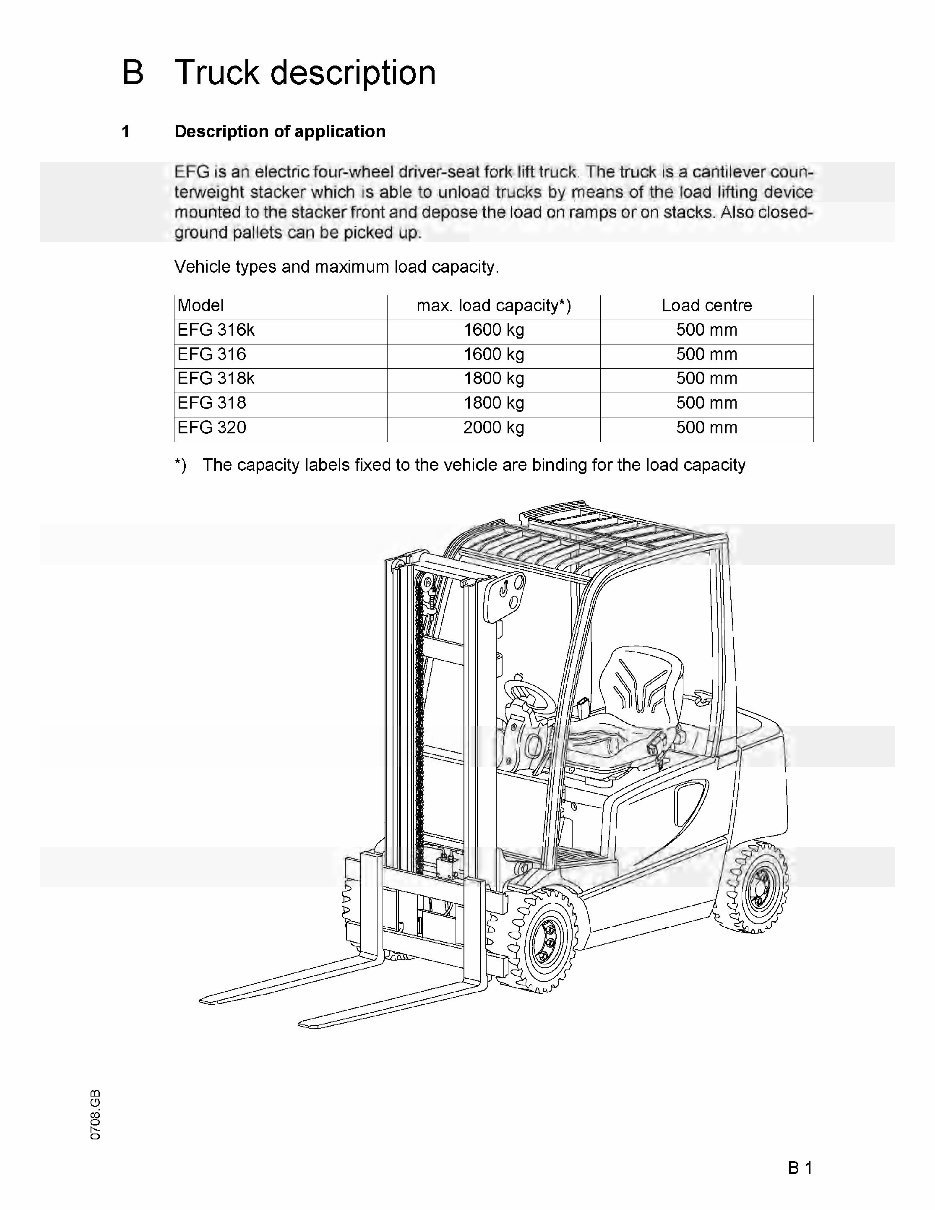
EFG is an electric four-wheel driver-seat fork lift truck. The truck is a cantilever coun¬
terweight stacker which is able to unload trucks by means of the load lifting device
mounted to the stacker front and depose the load on ramps or on stacks. Also closed-
ground pallets can be picked up.
Vehicle types and maximum load capacity.
Model max. load capacity*) Load centre
EFG 316k 1600 kg 500 mm
EFG 316 1600 kg 500 mm
EFG 318k 1800 kg 500 mm
EFG 318 1800 kg 500 mm
EFG 320 2000 kg 500 mm
*) The capacity labels fixed to the vehicle are binding for the load capacity
h-
O
B 1
2 Description of assemblies and functions
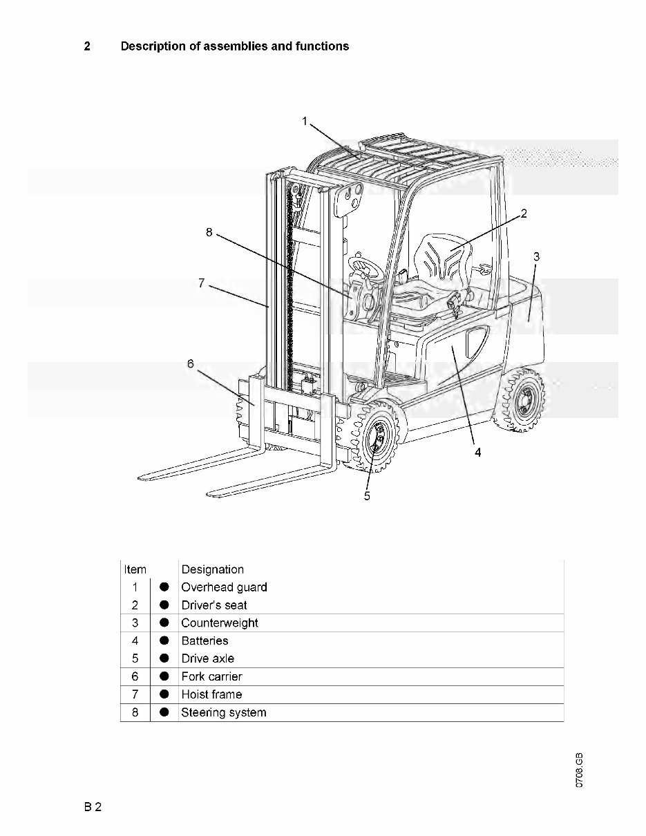
Item Designation
1
•
Overhead guard
2
•
Driver's seat
3
•
Counterweight
4
•
Batteries
5
•
Drive axle
6
•
Fork carrier
7
•
Hoist frame
8
•
Steering system
m
O
cd
o
h-
o
B 2
You're Reading a Preview
What's Included?
 Lifetime Access
Fast Download Speeds
Online & Offline Access
Access PDF Contents & Bookmarks
Full Search Facility
Print one or all pages of your manual
$46.99
$61.99
Jungheinrich Electric Lift Truck EFG 316, EFG 318, EFG 320 (08.2004-12.2008) Workshop Service Manual
Viewed 44 Times Today

What's Included?
Lifetime Access
Fast Download Speeds
Online & Offline Access
Access PDF Contents & Bookmarks
Full Search Facility
Print one or all pages of your manual
$46.99
$61.99

Secure transaction
What's Included?
Lifetime Access
Fast Download Speeds
Online & Offline Access
Access PDF Contents & Bookmarks
Full Search Facility
Print one or all pages of your manual
Description
Get your hands on the Illustrated Factory Workshop Service Manual for Jungheinrich Electric Lift Truck Type EFG 3xx. This original factory manual is a comprehensive resource for Jungheinrich Forklift Trucks, featuring high-quality images, circuit diagrams, and detailed instructions to assist you in the operation and repair of your truck. The manual is printable and contains searchable text for easy access.
- Covered models:
- EFG 316 (08.2004-12.2008)
- EFG 316K (08.2004-12.2008)
- EFG 318 (08.2004-12.2008)
- EFG 318K (08.2004-12.2008)
- EFG 320 (08.2004-12.2008)
Specifications:
- Format: 395 Pages
- Language: English
Contents:
- Operating Instructions
- Technical Description of Components
- Multi-Pilot 2xx Component Arrangement
- Solo Pilot 2xx Component Arrangement
- Multi-Pilot 3xx Component Arrangement
- Solo Pilot 3xx Component Arrangement
- Chassis/Superstructure:
- Drive
- Traction motor
- Transmission
- Wheels/Axles
- Travel switch/Accelerator pedal
- Brake system
- Brake pedal
- Parking brake
- Multi-plate brake
- Steering system
- Steering column
- EFG 2xx swivelling bolster
- EFG 3xx Steering Axle
- Power steering pump
- Steering system block diagram
- Chassis / load section connection
- Tilt cylinder
- Hydraulic system
- Control panel
- Control valve
- Pump motor / pump / pressure filter
- Electrical System
- Solo Pilot block diagram
- Multi Pilot block diagram
- Information and Service Display
- INFO displays
- Effective hours on/off, sound on/off
- Resetting the service interval counter
- Resetting the UW interval counter
- Activating / deactivating operating programs
- Test and Setting Values / General Truck Data EFG 2xx / 3xx
- Truck Maintenance
- Service Manual Items
- Steering angle sensor replacement / adjustment
- Steering angle potentiometer replacement / adjustment
- Brake multi-plate replacement
- Braking distances, minimum braking ratio
- Main brake cylinder (single stage)
- Guidelines for brake line installation
- Screw connection torques in brake systems
- Brake fluid replacement
- Parking brakes
- Steering auxiliary motor connection layout
- Outer cylinder replacement
- Check dimensions and settings for masts with angled support rollers
- Load chain elongation testing
- Forks
- Control valve standard setting
- Assembly instructions for die ring screw connections
- Lowering brakes and line brake safety devices
- Notes on how to avoid accidents and material damage during maintenance, test and repair work on industrial trucks with electronic components
- Notes on how to avoid malfunctions and material damage when cleaning an industrial truck
- Colour coding key
- Wheel bolt disassembly / assembly
- Tilt speed setting
- Sensor Bearing Disassembly/Assembly
- AS 4812F and AS 4814H CAN Bus Controllers
- LISA and Parameters
- Electrical Wiring Diagrams
- Hydraulic Diagrams


