

Jungheinrich Fork Truck Type DFG/TFG 316S/320S/420S/425S/430S/540S/545S/550S Workshop Service Manual
What's Included?
Fast Download Speeds
Offline Viewing
Access Contents & Bookmarks
Full Search Facility
Print one or all pages of your manual
tUNGHEINRICH DFG / TFG 16-50 A/B/C -K / -S
01.11 0.1
@>
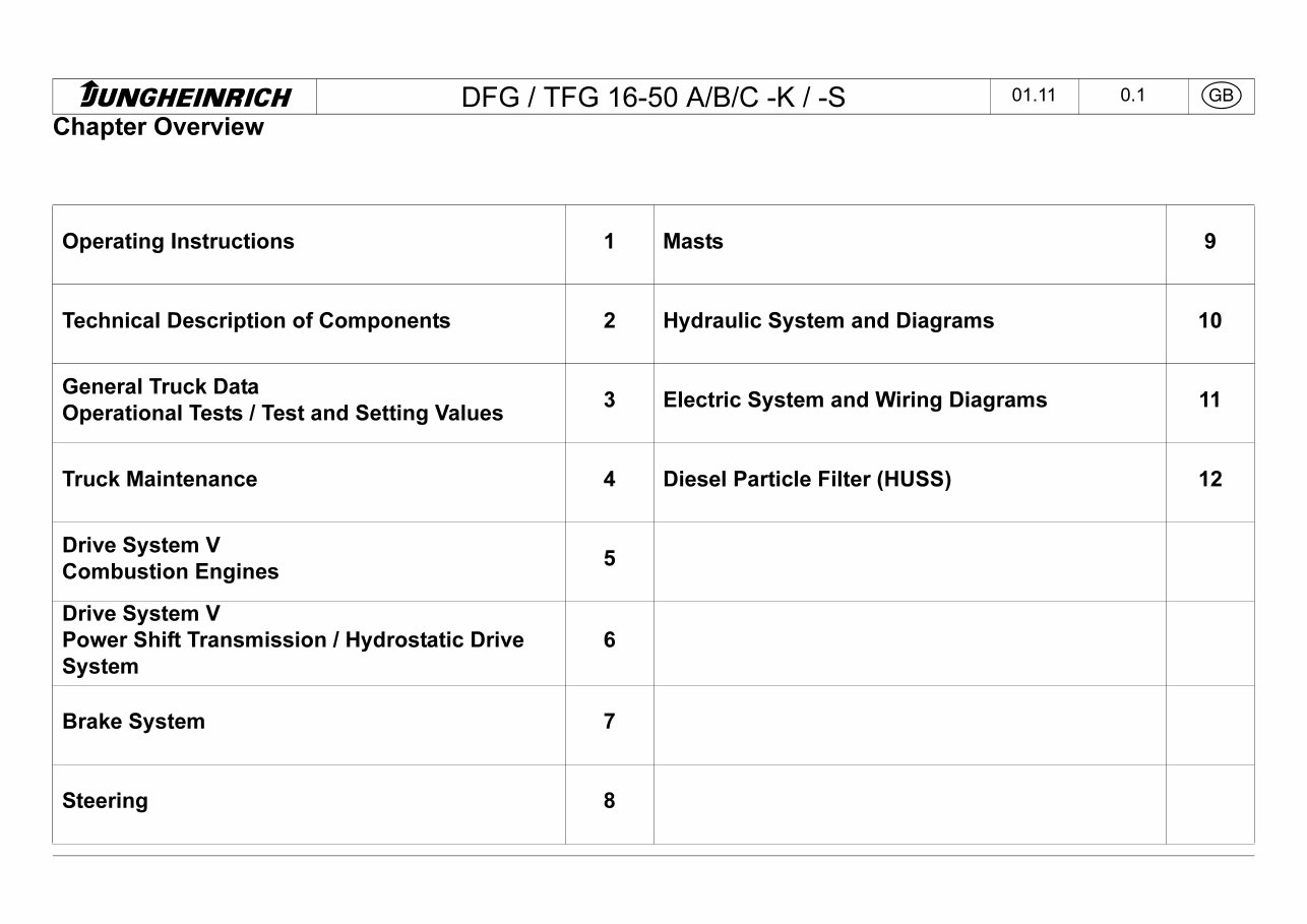
Chapter Overview
Operating Instructions 1 Masts 9
Technical Description of Components 2 Hydraulic System and Diagrams 10
General Truck Data
Operational Tests / Test and Setting Values
3 Electric System and Wiring Diagrams 11
Truck Maintenance 4 Diesel Particle Filter (HUSS) 12
Drive System V
Combustion Engines
5
Drive System V
Power Shift Transmission / Hydrostatic Drive
System
6
Brake System 7
Steering 8
HUNGHEINRICH
DFG / TFG 16-50 A/B/C -K / -S 09.04 1.1
(GB)
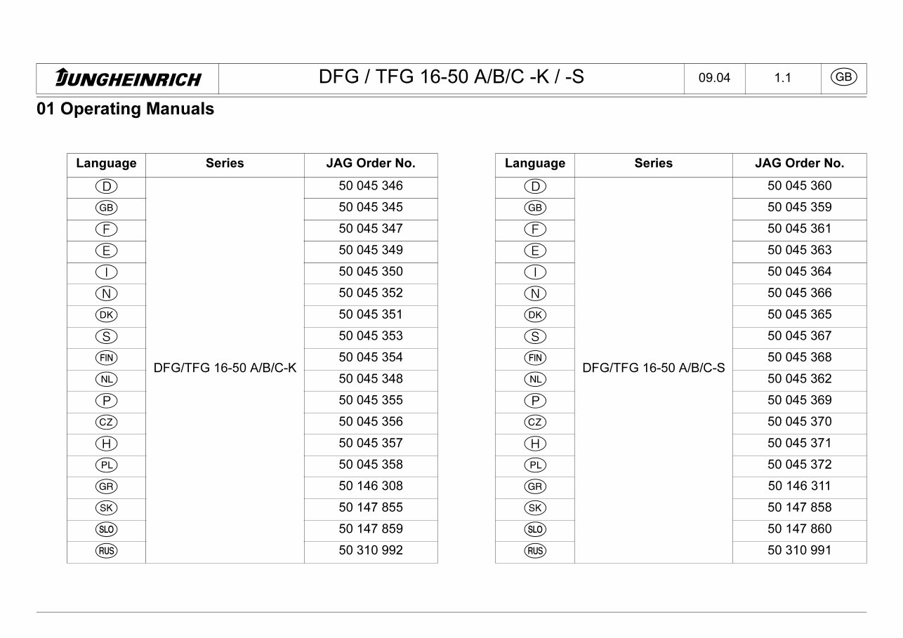
01 Operating Manuals
Language Series JAG Order No.
®
50 045 346
(gb) 50 045 345
CD
50 045 347
©
50 045 349
CD
50 045 350
®
50 045 352
(DK) 50 045 351
®
50 045 353
(RN)
DFG/TFG 16-50 A/B/C-K
50 045 354
(NL) 50 045 348
®
50 045 355
©
50 045 356
®
50 045 357
(PL) 50 045 358
(GR) 50 146 308
(SK) 50 147 855
(SLO) 50 147 859
(RUS) 50 310 992
Language Series JAG Order No.
®
50 045 360
(GB) 50 045 359
©
50 045 361
©
50 045 363
®
50 045 364
®
50 045 366
(DK) 50 045 365
©
50 045 367
@>
DFG/TFG 16-50 A/B/C-S
50 045 368
(NL) 50 045 362
©
50 045 369
©
50 045 370
®
50 045 371
(PL) 50 045 372
©
50 146 311
©
50 147 858
(SLO) 50 147 860
(RUS) 50 310 991
tUNGHEINMCH DFG 1TFG 1 6-50 A/B/C -K / -S
04.07 2.1 (GB)
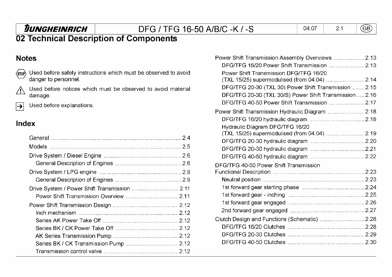
02 Technical Description of Components
Notes
<stop>
Used before safety instructions which must be observed to avoid
danger to personnel.
Used before notices which must be observed to avoid material
damage.
p>|
Used before explanations.
Index
General 2.4
Models 2.5
Drive System / Diesel Engine 2.6
General Description of Engines 2.6
Drive System / LPG engine 2.9
General Description of Engines 2.9
Drive System / Power Shift Transmission 2.11
Power Shift Transmission Overview 2.11
Power Shift Transmission Design 2.12
Inch mechanism 2.12
Series AK Power Take Off 2.12
Series BK / CK Power Take Off 2.12
AK Series Transmission Pump 2.12
Series BK / CK Transmission Pump 2.12
Transmission control valve 2.12
Power Shift Transmission Assembly Overviews 2.13
DFG/TFG 16/20 Power Shift Transmission 2.13
Power Shift Transmission DFG/TFG 16/20
(TXL 15/25) supermodulised (from 04.04) 2.14
DFG/TFG 20-30 (TXL 30) Power Shift Transmission 2.15
DFG/TFG 20-30 (TXL 30/S) Power Shift Transmission ..... 2.16
DFG/TFG 40-50 Power Shift Transmission 2.17
Power Shift Transmission Hydraulic Diagram 2.18
DFG/TFG 16/20 hydraulic diagram 2.18
Hydraulic Diagram DFG/TFG 16/20
(TXL 15/25) supermodulised (from 04.04) 2.19
DFG/TFG 20-30 hydraulic diagram 2.20
DFG/TFG 20-30 hydraulic diagram 2.21
DFG/TFG 40-50 hydraulic diagram 2.22
DFG/TFG 40-50 Power Shift Transmission
Functional Description 2.23
Neutral position 2.23
1st forward gear starting phase 2.24
1st forward gear -inching 2.25
1st forward gear engaged 2.26
2nd forward gear engaged 2.27
Clutch Design and Functions (Schematic) 2.28
DFG/TFG 16/20 Clutches 2.28
DFG/TFG 20-30 Clutches 2.29
DFG/TFG 40-50 Clutches 2.30
tUNGHEINRICH DFG 1TFG 1 6-50 A/B/C -K / -S
04.07 2.2 (GB)
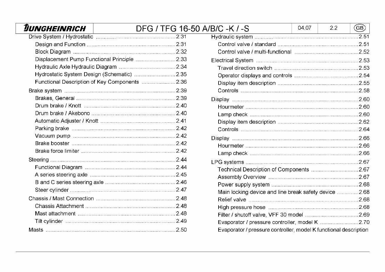
Drive System / Hydrostatic 2.31
Design and Function 2.31
Block Diagram 2.32
Displacement Pump Functional Principle 2.33
Hydraulic Axle Hydraulic Diagram 2.34
Hydrostatic System Design (Schematic) 2.35
Functional Description of Key Components 2.36
Brake system 2.39
Brakes, General 2.39
Drum brake / Knott 2.40
Drum brake / Akebono 2.40
Automatic Adjuster / Knott 2.41
Parking brake 2.42
Vacuum pump 2.42
Brake booster 2.42
Brake force limiter 2.42
Steering 2.44
Functional Diagram 2.44
A series steering axle 2.45
B and C series steering axle 2.46
Steer cylinder 2.47
Chassis / Mast Connection 2.48
Chassis Attachment 2.48
Mast attachment 2.48
Tilt cylinder 2.49
Masts 2.50
Hydraulic system 2.51
Control valve / standard 2.51
Control valve / multi-functional 2.52
Electrical System 2.53
Travel direction switch 2.53
Operator displays and controls 2.54
Display item description 2.55
Controls 2.58
Display 2.60
Hourmeter 2.60
Lamp check 2.60
Display item description 2.62
Controls 2.64
Display 2.66
Hourmeter 2.66
Lamp check 2.66
LPG systems 2.67
Technical Description of Components 2.67
Assembly Overview 2.67
Power supply system 2.68
Main locking device and line break safety device 2.68
Relief valve 2.68
High pressure hose 2.68
Filter / shutoff valve, VFF 30 model 2.69
Evaporator/ pressure controller, model K 2.70
Evaporator /pressure controller, model K functional description
tUNGHEINRICH DFG 1TFG 1 6-50 A/B/C -K / -S
04.07 2.3 (GB)
2.71
Gas air mixer, model CA 100 2.72
Gas air mixer, model CA 100 functional description 2.73
Gas air mixer, model CA 55 2.74
Mazda FE / Hoof speed limiter 2.74
DFG/TFG 40-50 CS solenoids 2.75
DFG/TFG 40-50 CS hydraulic spring-loaded brake 2.76
TFG 20-30 BK/BS and TFG 40-50 CK/CS ignition module ...2.76
tUNGHE/NRICH DFG 1TFG 1 6-50 A/B/C -K / -S
04.07 2.4 (GB)
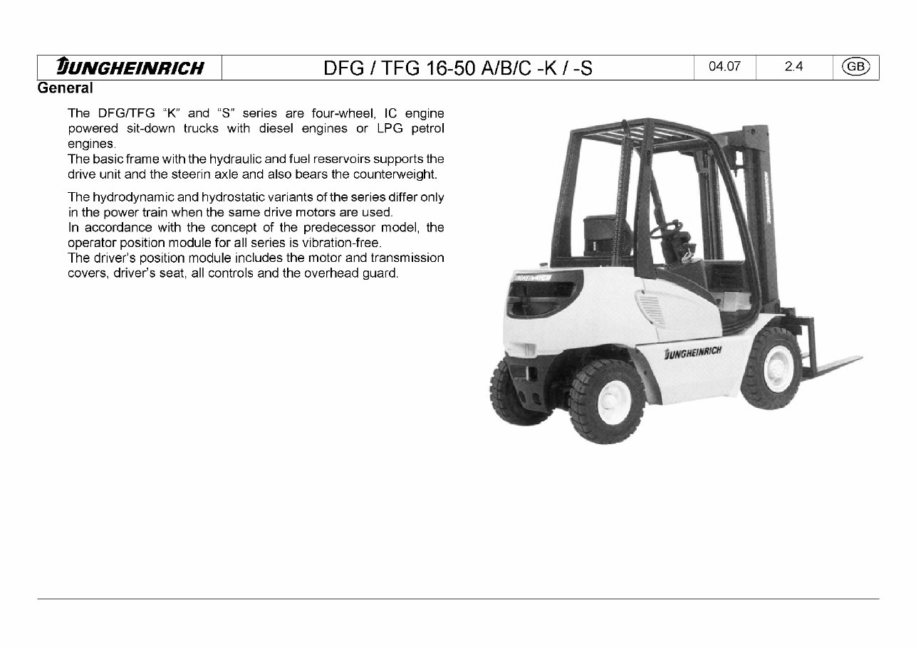
General
The DFG/TFG "K" and "S" series are four-wheel, IC engine
powered sit-down trucks with diesel engines or LPG petrol
engines.
The basic frame with the hydraulic and fuel reservoirs supports the
drive unit and the steerin axle and also bears the counterweight.
The hydrodynamicand hydrostatic variants of the series differ only
in the power train when the same drive motors are used.
In accordance with the concept of the predecessor model, the
operator position module for all series is vibration-free.
The driver's position module includes the motor and transmission
covers, driver's seat, all controls and the overhead guard.
tjUNGH£!M>aj
tUNGHEINRICH DFG / TFG 16-50 A/B/C -K / -S
04.07 2.5 (GB)
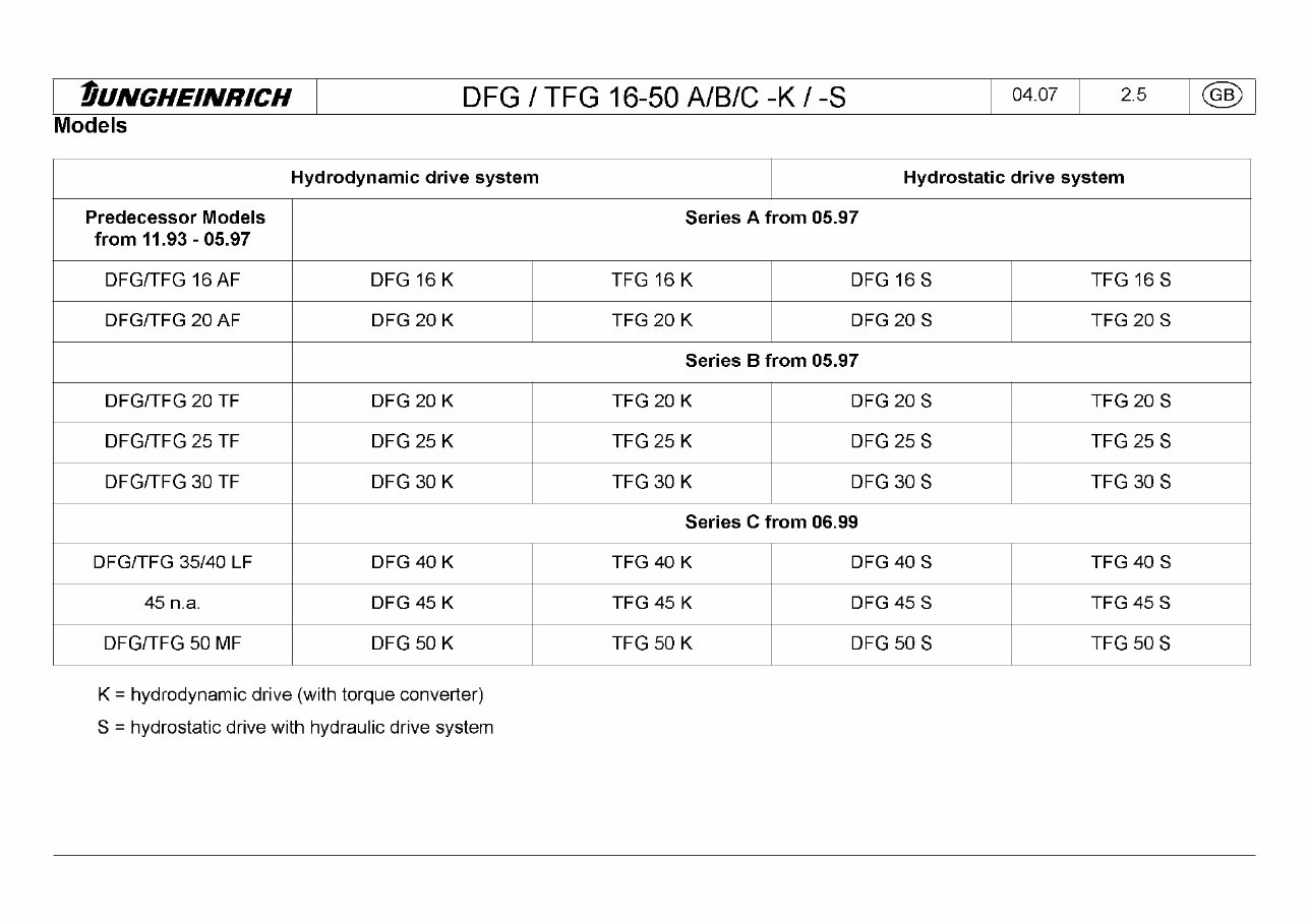
Models
Hydrodynamic drive system Hydrostatic drive system
Predecessor Models
from 11.93-05.97
Series A from 05.97
DFG/TFG 16 AF DFG 16 K TFG 16 K DFG 16 S TFG 16 S
DFG/TFG 20 AF DFG 20 K TFG 20 K DFG 20 S TFG 20 S
Series B from 05.97
DFG/TFG 20 TF DFG 20 K TFG 20 K DFG 20 S TFG 20 S
DFG/TFG 25 TF DFG 25 K TFG 25 K DFG 25 S TFG 25 S
DFG/TFG 30 TF DFG 30 K TFG 30 K DFG 30 S TFG 30 S
Series C from 06.99
DFG/TFG 35/40 LF DFG 40 K TFG 40 K DFG 40 S TFG 40 S
45 n.a. DFG 45 K TFG 45 K DFG 45 S TFG 45 S
DFG/TFG 50 MF DFG 50 K TFG 50 K DFG 50 S TFG 50 S
K = hydrodynamic drive (with torque converter)
S = hydrostatic drive with hydraulic drive system
tUNGHEINMCH DFG 1TFG 1 6-50 A/B/C -K / -S
04.07 2.6 (GB)
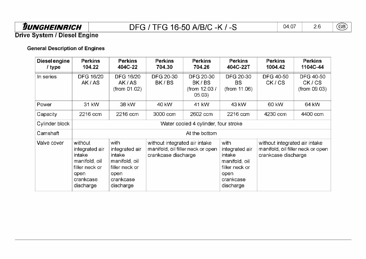
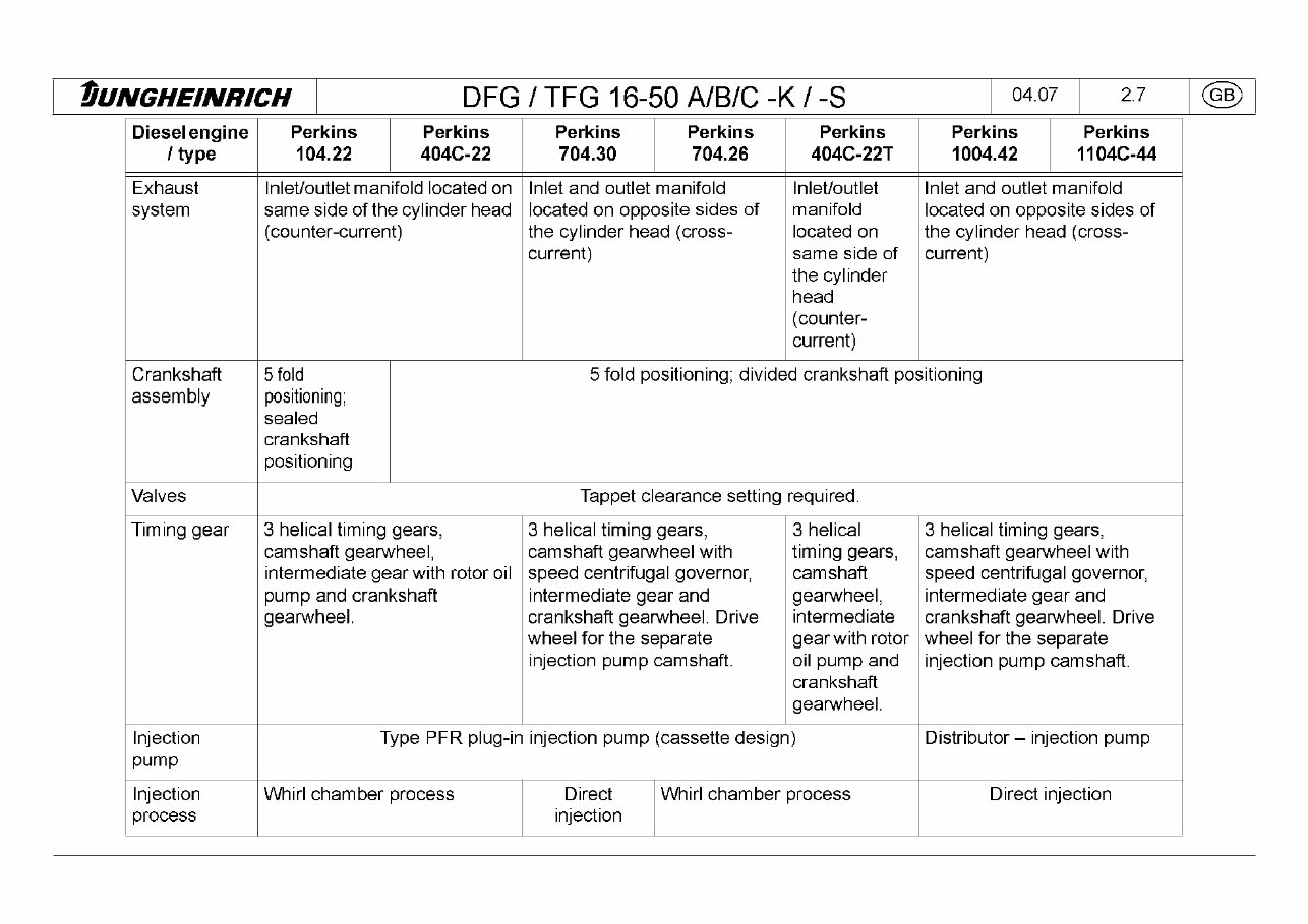
Drive System I Diesel Engine
General Description of Engines
Diesel engine
1 type
Perkins
104.22
Perkins
404C-22
Perkins
704.30
Perkins
704.26
Perkins
404C-22T
Perkins
1004.42
Perkins
1 1 04C-44
In series DFG 16/20
AK/AS
DFG 16/20
AK/AS
(from 01 .02)
DFG 20-30
BK/BS
DFG 20-30
BK/BS
(from 12.03/
05.03)
DFG 20-30
BS
(from 11.06)
DFG 40-50
CK/CS
DFG 40-50
CK/CS
(from 09.03)
Power 31 kW 38 kW 40 kW 41 kW 43 kW 60 kW 64 kW
Capacity 2216 ccm 2216 ccm 3000 ccm 2602 ccm 2216 ccm 4230 ccm 4400 ccm
Cylinder block Water cooled 4 cylinder, four stroke
Camshaft At the bottom
Valve cover without
integrated air
intake
manifold, oil
filler neck or
open
crankcase
discharge
with
integrated air
intake
manifold, oil
filler neck or
open
crankcase
discharge
without integrated air intake
manifold, oil filler neck or open
crankcase discharge
with
integrated air
intake
manifold, oil
filler neck or
open
crankcase
discharge
without integrated air intake
manifold, oil filler neck or open
crankcase discharge
tUNGHEINRICH DFG 1TFG 1 6-50 A/B/C -K / -S
04.07 2.7 (GB)
Diesel engine
/ type
Perkins
104.22
Perkins
404C-22
Perkins
704.30
Perkins
704.26
Perkins
404C-22T
Perkins Perkins
1004.42 1 1 04C-44
Exhaust
system
Inlet/outlet manifold located on
same side of the cylinder head
(counter-current)
Inlet and outlet manifold
located on opposite sides of
the cylinder head (cross¬
current)
Inlet/outlet
manifold
located on
same side of
the cylinder
head
(counter-
current)
Inlet and outlet manifold
located on opposite sides of
the cylinder head (cross¬
current)
Crankshaft
assembly
5 fold
positioning;
sealed
crankshaft
positioning
5 fold positioning; divided crankshaft positioning
Valves Tappet clearance setting required.
Timing gear 3 helical timing gears,
camshaft gearwheel,
intermediate gear with rotor oil
pump and crankshaft
gearwheel.
3 helical timing gears,
camshaft gearwheel with
speed centrifugal governor,
intermediate gear and
crankshaft gearwheel. Drive
wheel for the separate
injection pump camshaft.
3 helical
timing gears,
camshaft
gearwheel,
intermediate
gear with rotor
oil pump and
crankshaft
gearwheel.
3 helical timing gears,
camshaft gearwheel with
speed centrifugal governor,
intermediate gear and
crankshaft gearwheel. Drive
wheel for the separate
injection pump camshaft.
Injection
pump
Type PFR plug-in injection pump (cassette design) Distributor - injection pump
Injection
process
Whirl chamber process Direct
injection
Whirl chamber process Direct injection
tUNGHEINRICH DFG 1TFG 1 6-50 A/B/C -K / -S
04.07 2.8 (GB)
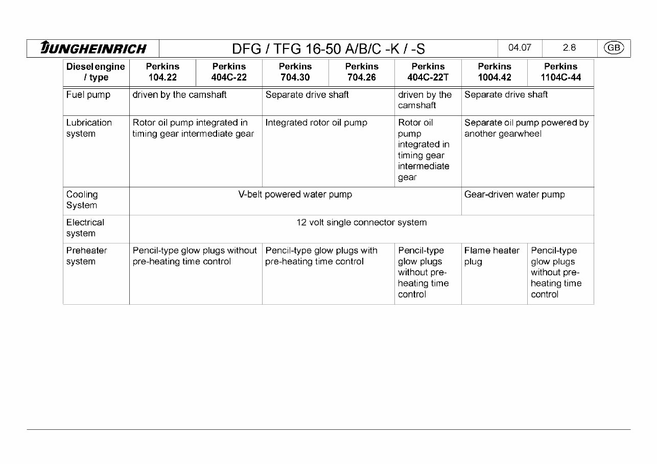
Diesel engine
/ type
Perkins Perkins
104.22 404C-22
Perkins Perkins
704.30 704.26
Perkins
404C-22T
Perkins
1004.42
Perkins
1 1 04C-44
Fuel pump driven by the camshaft Separate drive shaft driven by the
camshaft
Separate drive shaft
Lubrication
system
Rotor oil pump integrated in
timing gear intermediate gear
Integrated rotor oil pump Rotor oil
pump
integrated in
timing gear
intermediate
gear
Separate oil pump powered by
another gearwheel
Cooling
System
V-belt powered water pump Gear-driven water pump
Electrical
system
12 volt single connector system
Preheater
system
Pencil-type glow plugs without
pre-heating time control
Pencil-type glow plugs with
pre-heating time control
Pencil-type
glow plugs
without pre¬
heating time
control
Flame heater
plug
Pencil-type
glow plugs
without pre¬
heating time
control
You're Reading a Preview
What's Included?
Fast Download Speeds
Offline Viewing
Access Contents & Bookmarks
Full Search Facility
Print one or all pages of your manual
$48.99
Viewed 35 Times Today


Secure transaction
What's Included?
Fast Download Speeds
Offline Viewing
Access Contents & Bookmarks
Full Search Facility
Print one or all pages of your manual
$48.99
- Original Illustrated Factory Workshop Service Manual for Jungheinrich Fork Truck Type DFG/TFG 316S-550S.
- Covered models:
- DFG 316S (07.2004-06.2008)
- DFG 320S (07.2004-06.2008)
- DFG 420S (07.2004-06.2008)
- DFG 425S (07.2004-06.2008)
- DFG 430S (07.2004-06.2008)
- DFG 540S (07.2004-06.2008)
- DFG 545S (07.2004-06.2008)
- DFG 550S (07.2004-06.2008)
- TFG 316S (07.2004-06.2008)
- TFG 320S (07.2004-06.2008)
- TFG 420S (07.2004-06.2008)
- TFG 425S (07.2004-06.2008)
- TFG 430S (07.2004-06.2008)
- TFG 540S (07.2004-06.2008)
- TFG 545S (07.2004-06.2008)
- TFG 550S (07.2004-06.2008)
- Language: English
- Contained set of Manuals:
- Service Manual, 753 Pages
- Contents:
- Technical Description of Components
- General Truck Data. Operational Tests / Test and Setting Values
- Truck Maintenance
- Drive System V. Combustion Engines
- Drive System V. Power Shift Transmission / Hydrostatic Drive System
- Brake System
- Steering
- Masts
- Hydraulic System and Diagrams
- Electric System and Wiring Diagrams
- Diesel Particle Filter (HUSS)
- Operating Manual, 147 Pages
- Contents:
- A Correct Use and Application of the Truck
- B Description of Truck
- Description of Use
- Description of Assemblies and Function
- Truck
- Mast
- Changes in operational requirements
- Safety devices
- Technical Data -- Standard Equipment
- Data tables -- DFG/TFG 316s/320s
- Data tables -- DFG/TFG 420s--430s
- Data tables -- DFG/TFG 540s--550s
- Labels and Plates
- Truck Rating Plate
- Load diagrams
- C Transportation and Commissioning
- Transportation
- Commissioning
- D Truck Refuelling
- Safety Conditions for Handling Diesel Fuel and Liquid Petroleum Gas
- Filling with Diesel Fuel
- Changing the Gas Bottle
- Trucks fitted with Twin--Gas Bottles
- E Operation
- Safety Regulations Governing the Operation of the Forklift Truck
- Description of Drivers Controls and Display Elements
- Checks and Activities Before Daily Use
- Using the Truck
- Start Process TFG
- Start Process DFG
- Fault Displays during Operation
- Operation of the Forklift Truck
- Safety regulations applicable when operating the truck
- Driving
- Steering
- Braking
- Operating the Mast and Attachments
- Picking Up, Transporting and Setting Down Load Units
- Instructions for the use of restraint belts
- Parking the Truck Safely
- Engine housing and service covers
- Towing
- Towing Trailers
- Trailer loads
- Fault Locating Operations
- F Truck Maintenance
- Operational Safety and Environmental Protection
- Safety Regulations Applicable to Truck Maintenance
- Servicing and Inspection
- Maintenance Check-list DFG/TFG
- Maintenance Check-list DFG
- Maintenance Check-list TFG
- Coolant Specification
- Lubricant Specifications
- Fuel specification -- DFG
- Lubrication Chart
- Lubrication Diagram -- DFG/TFG 316s--550s
- Description of Maintenance and Repair Work
- Preparing the Truck for Maintenance and Repair Work
- Engine Maintenance TFG 316s/320s
- Engine Maintenance DFG 316s/320s
- Engine Maintenance TFG 420s--430s
- Engine Maintenance DFG 420s--430s
- Engine Maintenance TFG 540s--550s
- Engine Maintenance DFG 540s--550s
- Check Coolant Concentration
- Clean/Change Air Filter Cartridge
- Brakes
- Change Wheels
- Hydraulic System
- Electrical System
- Switch Gear and Control Potentiometers
- Exhaust System
- Decommissioning
- Inspection
- Safety checks to be performed at regular intervals and following any untoward incidents (D: Accident prevention check according to BGV D27)
- Storage
- Disposal
- Appendix for Diesel Engine Exhaust Gas Filter -- STX Type
- Introduction 1
- Regeneration 1


