Introduction 9803/3400 Issue 1 General This Service Manual is designed for the benefit of JCB Distributor Service Engineers who are receiving or have received, train- ing by JCB Technical Training Department. These personnel have a sound knowledge of safe workshop practices, safety procedures, and general techniques associated with the maintenance and repair of hydraulic earthmoving equipment. The replacement of oil seals, gaskets and any other components showing obvious signs of wear or damage is expected as a matter of course. Components should be cleaned and lubricated where appropriate, and any open hose or pipe connection must be blanked off to prevent the loss of hydraulic fluid or allow an ingress of dirt. Finally, please remember SAFETY COMES FIRST! Service Manual Layout This Service manual is compiled in sections, the first three are numbered and contain information as follows: 1 General Information 2 Care and Safety 3 Routine maintenance The remaining sections are alphabetically coded and deal with the overhaul and inspection of specific components, for exam- ple: A Attachments B Body and Framework ....etc. The page numbering in each alphabetically coded section is not continuous. This allows for the insertion of new information in later issues of this Service Manual. Section contents, technical data, circuit descriptions, operation descriptions etc are inserted, where necessary, at the beginning of each alphabetically coded section. Read the section contents to locate machine types, machine type identification is not listed on individual pages. All sections are listed on the front cover; tabbed divider cards align directly with each individual section for quick reference. Where a torque setting is given as a single figure it may be varied by plus or minus 3%. Torque figures indicated are for dry threads. Torque figures for lubricated threads can be reduced by one third. “Left Hand” and “Right Hand” are as viewed from the rear of the machine facing forwards. This Service Manual covers the following machine type: Teletruk Product Identification Number (PIN) 0788001
General Information Section 1 Section 1 i i 9803/3400 Issue 4* Identification - Vehicle Identification Number 1 - 1 - Unit Identification 1 - 1 - Typical Engine Identification Number 1 - 1 Torque Settings - Introduction - Zinc Plated Fasteners and Dacromet Fasteners 2 - 1 - Metric Grade 8.8 Bolts 2 - 1 - UNF Grade “S” Bolts 2 - 1 - Hydraulic Fittings & Torque Settings 2 - 2 - ‘O’ Ring Face Seal System 2 - 2 - Torque Stop Hose System 2 - 3 Service Tools - Numerical List 3 - 1 - Body and Framework 3 - 2 - Electrics 3 - 5 - Hydaulics 3 - 6 Sealing and Retaining Compounds 4 - 1 Contents Page No. * * * * * * *
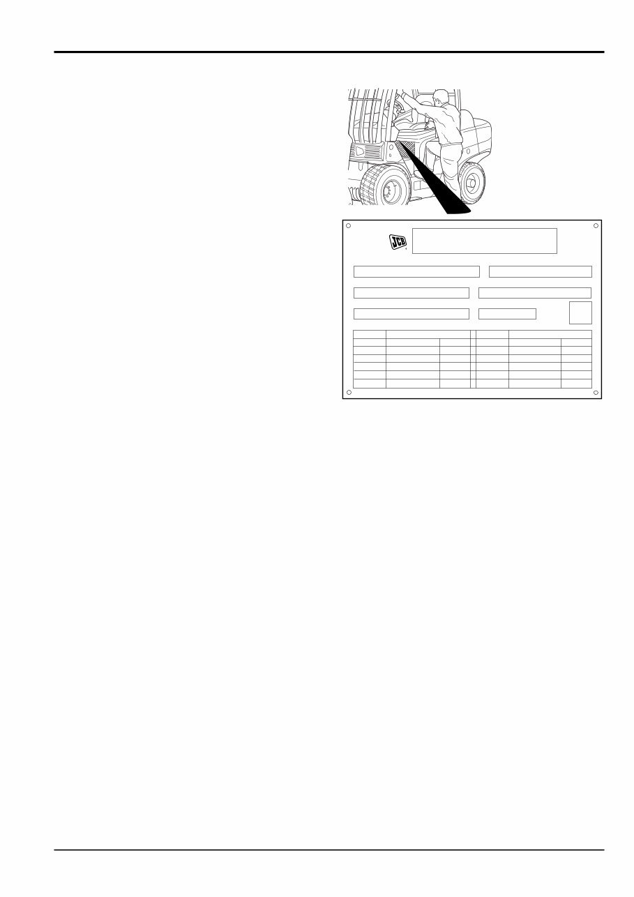
General Information Section 1 Section 1 1 - 1 1 - 1 9803/3400 Issue 3* Vehicle Identification Number (VIN) The Product Identification Number (PIN), transmission pump serial number and engine serial number positively identify the type of Teletruk that you have. These numbers are stamped on the machine VIN plate as shown in the following Figure. A typical VIN is a 17 digit number as follows: SLP TLT25 V E 0788001 SLP Manufacturer (JCB) TLT25 Machine Model (Teletruk) V Year (1997) E Country (England) 0788001 (PIN) Unit Identification To confirm the identity of your machine, check the VIN plate details against the serial numbers of each component. Typical Engine Identification Number This applies to the diesel engines only. HR 51245 U A B C A Engine Type KR = 4 cylinder naturally aspirated - up to machine serial number 892816. HP = 4 cylinder naturally aspirated - low emission stage 2 - from machine serial number 892817. HR = 4 cylinder turbo - low emission stage 2 - 3.5 machines only. Where the service procedure differ between the engine types, the text and or the illustration will specify. B Build Number C Country of Origin Identification CONSTRUCTOR MADE IN UK J.C.BAMFORD EXCAVATORS LTD. ROCESTER, STAFFS, ENGLAND. Vehicle Identification No. Product Identification No. ENGINE SERIAL No. WEIGHT PUMP SERIAL No. YEAR OF MANUFACTURE MODEL 80/1269/EEC MODEL 80/1269/EEC POWER KW R.P.M. POWER KW R.P.M. 817/16599 * 401571
General Information Section 1 Section 1 2 - 1 2 - 1 9803/3400 Issue 2* Torque Settings Introduction - Zinc Plated Fasteners and Dacromet Fasteners JCB Teletruks are assembled using an improved type of corrosion resistant finish. This type of finish is called Dacromet and replaces the original Zinc and Yellow plating used on earlier machines. The two types of fasteners can be readily identified by colour and part number suffix as follows: Fastener Type Colour Part Number Zinc and Yellow Golden finish ‘Z’ (e.g. 1315/3712Z) Dacromet Mottled silver finish ‘D’ (e.g. 1315/3712D) Note: As the Dacromet fasteners have a lower torque setting than the Zinc and Yellow fasteners, the torque figures used must be relevant to the type of fasteners. Note: A Dacromet bolt should not be used in conjunction with a Zinc and Yellow plated nut, as this could change the torque characteristics of the torque settings further. For the same reason, a Dacromet nut should not be used in conjunction with a Zinc and Yellow plated bolt. Use only where no torque setting is specified in the text. Values are for dry threads and may be within three per cent of the figures stated. For lubricated threads the values should be REDUCED by one third. Metric Grade 8.8 Bolts Bolt size Zinc Plated Fasteners Dacromet Fasteners Diameter Hexagon (A/F) Torque Settings Torque Settings mm mm Nm kgf m lbf ft Nm kgf m lbf ft M6 x 1.0 10 12 1.2 9 9 0.9 7 M8 x 1.25 13 28 3.0 21 22.5 2.3 17 M10 x 1.5 17 56 5.7 42 47.5 4.8 35 M12 x 1.75 19 98 10 72 80 8.2 59 M14 x 2 22 133 13.6 98 M16 x 2 24 244 25 180 200 20.4 148 M18 x 2.5 27 350 36 258 278 28.4 205 M20 x 2.5 30 476 48 352 392 40 289 M24 x 3 36 822 84 607 675 69 498 M30 x 3.5 46 1633 166 1205 1348 138 994 UNF Grade 'S' Bolts Bolt Size Hexagon (A/F) Torque Settings in (mm) in Nm kgf m lbf ft 1 /4 (6.3) 7 /16 14 1.4 10 5 /16 (7.9) 1 /2 28 2.8 20 3 /8 (9.5) 9 /16 49 5.0 36 7 /16 (11.1) 5 /8 78 8.0 58 1 /2 (12.7) 3 /4 117 12.0 87 9 /16 (14.3) 13 /16 170 17.3 125 5 /8 (15.9) 15 /16 238 24.3 175 3 /4 (19.0) 1 1 /8 407 41.5 300 7 /8 (22.2) 1 5 /16 650 66.3 480 1 (25.4) 1 1 /2 970 99.0 715 1 1 /4 (31.7) 1 7 /8 1940 198.0 1430 1 1 /2 (38.1) 2 1 /4 3390 345.0 2500 Note: All bolts used on JCB machines are high tensile and must not be replaced by bolts of a lesser tensile specification. *
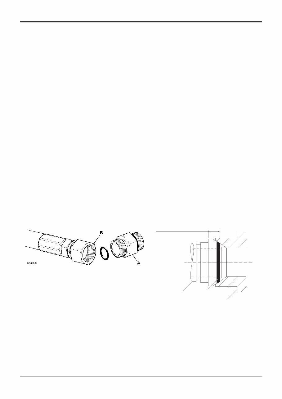
General Information Section 1 Section 1 2 - 2 2 - 2 9803/3400 Issue 1 Hydraulic Fittings & Torque Settings ‘O’ Ring Face Seal System Adaptors screwed into valve blocks Adaptors screwed into valve blocks, etc. seal onto an 'O' ring which is compressed into a 45 o seat machined in the face of the tapped port. Common Spanner Size (A/F) Tightening Torque Adaptor Size mm in. Nm lbf ft 1/4” BSP 19 0.75 18 13 3/8” BSP 22 0.875 31 23 1/2” BSP 27 1 49 36 5/8” BSP 30 60 44 3/4” BSP 32 1.25 81 60 1” BSP 38 1.5 129 95 1 1/4” BSP 206 152 SAE SAE Port Common Spanner Size (A/F) Tightening Torque Tube Size Thread Size mm in. Nm lbf ft 4 7/16 - 20 15.9 0.625 20 - 28 16.5 - 18.5 6 9/16 - 18 19.1 0.750 46 - 54 34 - 40 8 3/4 - 16 22.2 0.875 95 - 105 69 - 77 10 7/8 - 14 27.0 1.063 130 - 140 96 - 104 12 1.1/16 - 12 31.8 1.250 190 - 210 141 - 155 16 1.5/16 - 12 38.1 1.500 290 - 310 216 - 230 20 1.5/8 - 12 47.6 1.875 280 - 380 210 - 280 Hoses Screwed onto Adaptors Hoses B screwed onto adaptors A etc. seal onto an 'O' ring C which is compressed into a 45 o seat machined in the face of the adaptor port. Common Spanner Size (A/F) Tightening Torque Hose Size mm in. Nm lbf ft 1/8” BSP 14 14 10 1/4” BSP 19 0.75 24 18 3/8” BSP 22 0.875 33 24 1/2” BSP 27 1 44 33 5/8” BSP 30 58 43 3/4” BSP 32 1.25 84 62 1” BSP 38 1.5 115 85 1 1/4” BSP 189 140 1 1/2” BSP 244 180 B A C A438690 Dimension will vary depending on torque applied.
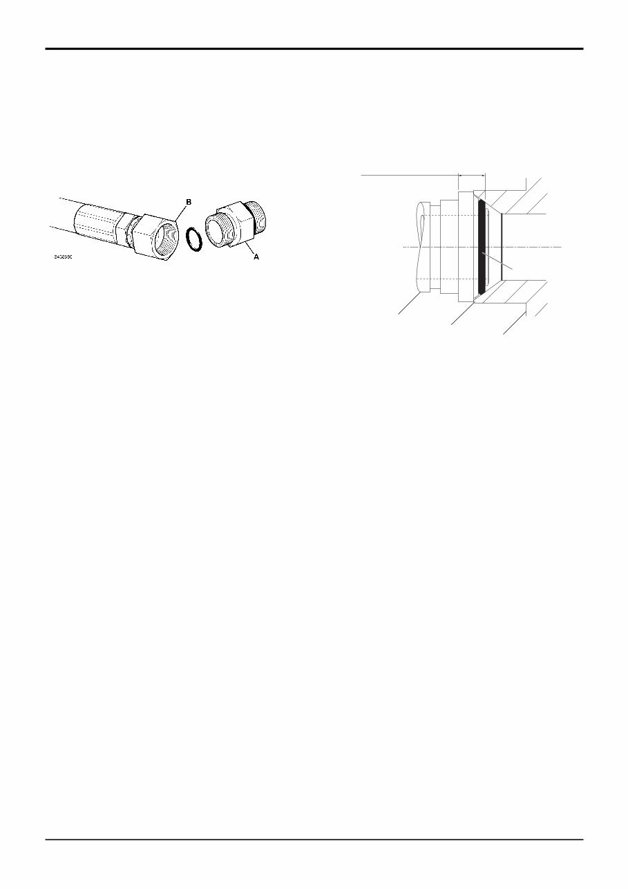
General Information Section 1 Section 1 2 - 3 2 - 3 9803/3400 Issue 1 Hydraulic Fittings & Torque Settings Torque Stop Hose System 'Torque Stop' Hoses B screwed onto adaptors A etc. seal onto an 'O' ring C which is compressed into a 45 o seat machined in the face of the adaptor port. To prevent the ‘O’ ring being damaged as a result of over tightening, 'Torque Stop' Hoses have an additional shoulder, which acts as a physical stop. Common Spanner Size (A/F) Tightening Torque Hose Size mm in. Nm lbf ft 1/8” BSP 14 14 10 1/4” BSP 19 0.75 27 20 3/8” BSP 22 0.875 40 30 1/2” BSP 27 1 55 40 5/8” BSP 30 65 48 3/4” BSP 32 1.25 95 70 1” BSP 38 1.5 120 89 1 1/4” BSP 189 140 1 1/2” BSP 244 180 A438700 D B A C Minimum dimension fixed by shoulder D.
The JCB Teletruk forklift 2.0 D/G 2.5 D/G 3.0 D/G, 3.0D 4*4, 3.5D 4*4 Service Manual contains comprehensive information, diagrams, actual real photo illustrations, and schemes. These provide complete step-by-step operations for repair, servicing, technical maintenance, and troubleshooting procedures for your machine. This manual offers all the information needed for repairing your machine without the need for professional service.
One of the advantages of having digital files instead of a hard-printed manual is the ability to use the Search feature in Acrobat to quickly find specific information and print out exact pages as needed. The manual covers serial numbers 788001 onwards and has a publication number of 9803-9510. It is available in English language and has 609 pages with a file size of 247Mb.
The manual includes the following sections:
General Information
Care and Safety
Routine Maintenance
Attachments
Body and Framework
Electronics
Controls
Hydraulics
Transmission
Brakes
Steering
Engine
We have a comprehensive collection of manuals for JCB machines. If you have any questions or are looking for a specific manual, feel free to reach out to us. Have a great day!
Reviews
Q&A
Recently Viewed
5,521,897Happy Clients
2,594,462eManuals
1,120,453Trusted Sellers
15Years in Business
Price:
Actual Price:
JCB Forklift TELETRUK 2.0D/G 2.5D/G 3.0D/G 35 Service Manual









 Lifetime Access




