

OPERATOR’S CAB
H1.6FT, H1.8FT, 2.0FTS [F001];
H2.0-3.5FT (H40-70FT) [L177];
H4.0FT5/FT6, H4.5FTS5, H4.5FT6,
H5.0-5.5FT (H80, 90, 100, 110, 120FT)
[N005, P005];
H6.0FT, H7.0FT (H135FT, H155FT) [H006, J006]
PART NO. 1673866 100 SRM 1290

SAFETY PRECAUTIONS
MAINTENANCE AND REPAIR
• When lifting parts or assemblies, make sure all slings, chains, or cables are correctly fastened, and
that the load being lifted is balanced. Make sure the crane, cables, and chains have the capacity
to support the weight of the load.
• Do not lift heavy parts by hand, use a lifting mechanism.
• Wear safety glasses.
• DISCONNECT THE BATTERY CONNECTOR before doing any maintenance or repair on electric
lift trucks. Disconnect the battery ground cable on internal combustion lift trucks.
• Always use correct blocks to prevent the unit from rolling or falling. See HOW TO PUT THE LIFT
TRUCK ON BLOCKS in the Operating Manual or the Periodic Maintenance section.
• Keep the unit clean and the working area clean and orderly.
• Use the correct tools for the job.
• Keep the tools clean and in good condition.
• Always use HYSTER APPROVED parts when making repairs. Replacement parts must meet
or exceed the specifications of the original equipment manufacturer.
• Make sure all nuts, bolts, snap rings, and other fastening devices are removed before using force
to remove parts.
• Always fasten a DO NOT OPERATE tag to the controls of the unit when making repairs, or if the
unit needs repairs.
• Be sure to follow the WARNING and CAUTION notes in the instructions.
• Gasoline, Liquid Petroleum Gas (LPG), Compressed Natural Gas (CNG), and Diesel fuel are
flammable. Be sure to follow the necessary safety precautions when handling these fuels and
when working on these fuel systems.
• Batteries generate flammable gas when they are being charged. Keep fire and sparks away from
the area. Make sure the area is well ventilated.
NOTE: The following symbols and words indicate safety information in this
manual:
WARNING
Indicates a condition that can cause immediate death or injury!
CAUTION
Indicates a condition that can cause property damage!

Operator’s Cab Table of Contents
TABLE OF CONTENTS
General ............................................................................................................................................................... 1
Cab Replacement ............................................................................................................................................... 2
Remove, for Lift Truck Models H1.6FT, H1.8FT, 2.0FTS (F001); H2.0-3.5FT (H40-70FT) (L177);
and H4.0FT5/FT6, H4.5FTS5, H4.5FT6, H5.0-5.5FT (H80, 90, 100, 110, 120FT) (N005, P005) .............. 2
Install, for Lift Truck Models H1.6FT, H1.8FT, 2.0FTS (F001); H2.0-3.5FT (H40-70FT) (L177);
and H4.0FT5/FT6, H4.5FTS5, H4.5FT6, H5.0-5.5FT (H80, 90, 100, 110, 120FT) (N005, P005) .............. 13
Remove, for Lift Truck Models H6.0FT, H7.0FT (H135FT, H155FT) (H006, J006) .................................. 14
Install, for Lift Truck Models H6.0FT, H7.0FT (H135FT, H155FT) (H006, J006) ..................................... 18
Door Assemblies ................................................................................................................................................. 19
Right Side Door Assembly, Lift Truck Models H1.6FT, H1.8FT, 2.0FTS (F001); H2.0-3.5FT
(H40-70FT) (L177); and H4.0FT5/FT6, H4.5FTS5, H4.5FT6, H5.0-5.5FT (H80, 90, 100, 110,
120FT) (N005, P005) ..................................................................................................................................... 19
Remove ....................................................................................................................................................... 19
Disassemble ............................................................................................................................................... 24
Door Cover ............................................................................................................................................. 24
Heater Assembly ................................................................................................................................... 26
Door Lock Assembly.............................................................................................................................. 27
Windows ................................................................................................................................................ 28
Clean .......................................................................................................................................................... 28
Inspect ........................................................................................................................................................ 28
Assemble .................................................................................................................................................... 28
Windows ................................................................................................................................................ 28
Door Lock Assembly.............................................................................................................................. 28
Heater Assembly ................................................................................................................................... 29
Door Cover ............................................................................................................................................. 29
Install ......................................................................................................................................................... 29
Left Side Door Assembly, Lift Truck Models H1.6FT, H1.8FT, 2.0FTS (F001); H2.0-3.5FT
(H40-70FT) (L177); and H4.0FT5/FT6, H4.5FTS5, H4.5FT6, H5.0-5.5FT (H80, 90, 100, 110,
120FT) (N005, P005) ..................................................................................................................................... 29
Remove ....................................................................................................................................................... 29
Disassemble ............................................................................................................................................... 29
Door Cover ............................................................................................................................................. 29
Door Lock Assembly.............................................................................................................................. 31
Windows ................................................................................................................................................ 31
Clean .......................................................................................................................................................... 31
Inspect ........................................................................................................................................................ 31
Assemble .................................................................................................................................................... 31
Windows ................................................................................................................................................ 31
Door Lock Assembly.............................................................................................................................. 31
Door Cover ............................................................................................................................................. 31
Install ......................................................................................................................................................... 31
Right and Left Side Door Assemblies, Lift Truck Models H6.0FT, H7.0FT (H135FT, H155FT)
(H006, J006) ................................................................................................................................................... 32
Remove ....................................................................................................................................................... 32
Disassemble ............................................................................................................................................... 32
Door Cover ............................................................................................................................................. 32
Door Lock Assembly.............................................................................................................................. 34
Windows ................................................................................................................................................ 34
Clean .......................................................................................................................................................... 34
Inspect ........................................................................................................................................................ 34
Assemble .................................................................................................................................................... 35
©2008 HYSTER COMPANY i

Table of Contents Operator’s Cab
TABLE OF CONTENTS (Continued)
Windows ................................................................................................................................................ 35
Door Lock Assembly.............................................................................................................................. 35
Door Cover ............................................................................................................................................. 35
Install ......................................................................................................................................................... 36
Window Wipers Replacement ............................................................................................................................ 36
General ........................................................................................................................................................... 36
Front Wiper Assembly and Motor................................................................................................................. 36
Remove, Lift Truck Models H1.6FT, H1.8FT, 2.0FTS (F001) and H2.0-3.5FT (H40-70FT)
(L177) ......................................................................................................................................................... 36
Install, Lift Truck Models H1.6FT, H1.8FT, 2.0FTS (F001) and H2.0-3.5FT (H40-70FT) (L177) ........ 36
Remove, Lift Truck Models H4.0FT5/FT6, H4.5FTS5, H4.5FT6, H5.0-5.5FT (H80, 90, 100,
110, 120FT) (N005, P005) and H6.0FT, H7.0FT (H135FT, H155FT) (H006, J006) ............................... 38
Install, Lift Truck Models H4.0FT5/FT6, H4.5FTS5, H4.5FT6, H5.0-5.5FT (H80, 90, 100, 110,
120FT) (N005, P005) and H6.0FT, H7.0FT (H135FT, H155FT) (H006, J006)....................................... 38
Rear Wiper Assembly and Motor .................................................................................................................. 40
Remove, Lift Truck Models H1.6FT, H1.8FT, 2.0FTS (F001) ................................................................. 40
Install, Lift Truck Models H1.6FT, H1.8FT, 2.0FTS (F001) ................................................................... 40
Remove, Lift Truck Models H2.0-3.5FT (H40-70FT) (L177) ................................................................... 42
Install, Lift Truck Models H2.0-3.5FT (H40-70FT) (L177) ..................................................................... 42
Remove, Lift Truck Models H4.0FT5/FT6, H4.5FTS5, H4.5FT6, H5.0-5.5FT (H80, 90, 100,
110, 120FT) (N005, P005) ......................................................................................................................... 45
Install, Lift Truck Models H4.0FT5/FT6, H4.5FTS5, H4.5FT6, H5.0-5.5FT (H80, 90, 100, 110,
120FT) (N005, P005) ................................................................................................................................. 45
Remove, Lift Truck Models H6.0FT, H7.0FT (H135FT, H155FT) (H006, J006) .................................... 47
Install, Lift Truck Models H4.0FT5/FT6, H4.5FTS5, H4.5FT6, H5.0-5.5FT (H80, 90, 100, 110,
120FT) (N005, P005) and H6.0FT, H7.0FT (H135FT, H155FT) (H006, J006)....................................... 47
Window Replacement......................................................................................................................................... 49
General ........................................................................................................................................................... 49
Remove Door Window, Lift Truck Models H1.6FT, H1.8FT, 2.0FTS (F001); H2.0-3.5FT
(H40-70FT) (L177); and H4.0FT5/FT6, H4.5FTS5, H4.5FT6, H5.0-5.5FT (H80, 90, 100, 110,
120FT) (N005, P005) ..................................................................................................................................... 49
Install Door Windows, Lift Truck Models H1.6FT, H1.8FT, 2.0FTS (F001); H2.0-3.5FT
(H40-70FT) (L177); and H4.0FT5/FT6, H4.5FTS5, H4.5FT6, H5.0-5.5FT (H80, 90, 100, 110,
120FT) (N005, P005) ..................................................................................................................................... 50
Remove Door Window, Lift Truck Models H6.0FT, H7.0FT (H135FT, H155FT) (H006, J006) ................. 51
Install Door Window, Lift Truck Models H6.0FT, H7.0FT (H135FT, H155FT) (H006, J006) ................... 52
Heater Replacement .......................................................................................................................................... 52
Remove, for Lift Truck Models H6.0FT, H7.0FT (H135FT, H155FT) (H006, J006) .................................. 52
Install, for Lift truck Models H6.0FT, H7.0FT (H135FT, H155FT) (H006, J006) ..................................... 55
Light Replacement ............................................................................................................................................. 56
Work Lights (Front and Rear)....................................................................................................................... 56
Remove ....................................................................................................................................................... 56
Install ......................................................................................................................................................... 56
Strobe Light ................................................................................................................................................... 58
Remove ....................................................................................................................................................... 58
Install ......................................................................................................................................................... 58
Turn, Stop, Tail, and Backup Light .............................................................................................................. 59
Remove ....................................................................................................................................................... 59
Install ......................................................................................................................................................... 59
Front Marker/Turn Signal Lights ................................................................................................................. 59
Remove ....................................................................................................................................................... 59
ii

Operator’s Cab Table of Contents
TABLE OF CONTENTS (Continued)
Install ......................................................................................................................................................... 59
Display Switches ................................................................................................................................................ 60
Electrical Schematics......................................................................................................................................... 64
Optional Equipment .......................................................................................................................................... 67
Heavy Duty Pre-Cleaner ............................................................................................................................... 67
Remove ....................................................................................................................................................... 67
Clean .......................................................................................................................................................... 68
Inspect ........................................................................................................................................................ 68
Install ......................................................................................................................................................... 68
Fan.................................................................................................................................................................. 68
Remove ....................................................................................................................................................... 68
Install ......................................................................................................................................................... 68
Mirror ............................................................................................................................................................. 68
Remove ....................................................................................................................................................... 68
Install ......................................................................................................................................................... 68
Label Replacement............................................................................................................................................. 68
This section is for the following models:
H1.6FT, H1.8FT, 2.0FTS [F001];
H2.0-3.5FT (H40-70FT) [L177];
H4.0FT5/FT6, H4.5FTS5, H4.5FT6, H5.0-5.5FT (H80, 90, 100,
110, 120FT) [N005, P005];
H6.0FT, H7.0FT (H135FT, H155FT) [H006, J006]
iii

"THE
QUALITY
KEEPERS"
HYSTER
APPROVED
PARTS
100 SRM 1290 General
General
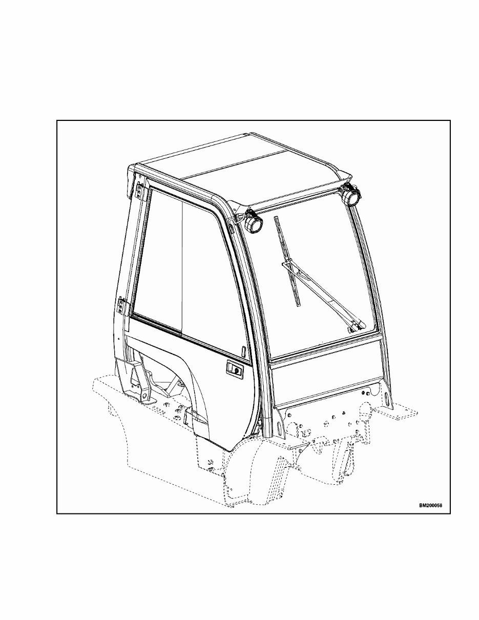
The overhead guard is an integral part of the opera-
tor cab. The operator cab is installed on a platform
above the main frame members. Step plates on both
sides of the lift truck provide access to the operator
cab. The operator cab is a separate unit and can
be removed as a complete unit from the module and
frame of the lift truck. See Figure 1.
Figure 1. Operator Cab
1
Cab Replacement 100 SRM 1290
Cab Replacement
REMOVE, FOR LIFT TRUCK MODELS
H1.6FT, H1.8FT, 2.0FTS (F001); H2.0-3.5FT
(H40-70FT) (L177); AND H4.0FT5/FT6,
H4.5FTS5, H4.5FT6, H5.0-5.5FT (H80, 90,
100, 110, 120FT) (N005, P005)
NOTE: The EZXchange™ bracket used on these
trucks to mount the LPG tank onto the counter-
weight come in two styles. One style of bracket
swings out to the side of the truck and the other
swings out to the side and drops down.
NOTE: Lift trucks equipped with LPG, make sure to
release the EZXchange™ bracket before opening the
hood.
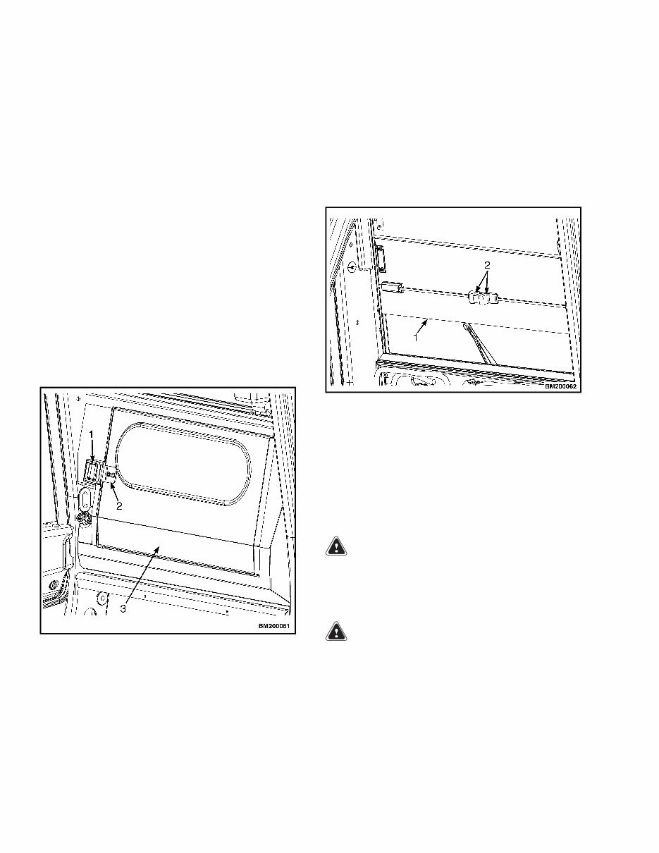
1. For lift truck models H1.6FT, H1.8FT, 2.0FTS
(F001), tilt the steering column to the UP posi-
tion, slide seat assembly forward, open rear door,
and open hood to disconnect battery. See Fig-
ure 2.
1. LATCH
2. HINGE
3. REAR DOOR
Figure 2. Rear Door and Latch for Lift Truck
Models H1.6FT, H1.8FT, 2.0FTS (F001)
2. For lift trucks models H2.0-3.5FT (H40-70FT)
(L177) and H4.0FT5/FT6; H4.5FTS5, H4.5FT6;
H5.0-5.5FT (H80, 90, 100, 110, 120FT) (N005,
P005), tilt the steering column to the UP po-
sition, slide seat assembly forward, open rear
sliding window and open the hood to disconnect
battery. See Figure 3.
1. REAR BOTTOM WINDOW
2. RELEASE LATCH
Figure 3. Rear Bottom Window for Lift Trucks
Models H2.0-3.5FT (H40-70FT) (L177) and
H4.0FT5/FT6, H4.5FTS5, H4.5FT6, H5.0-5.5FT
(H80, 90, 100, 110, 120FT) (N005, P005)
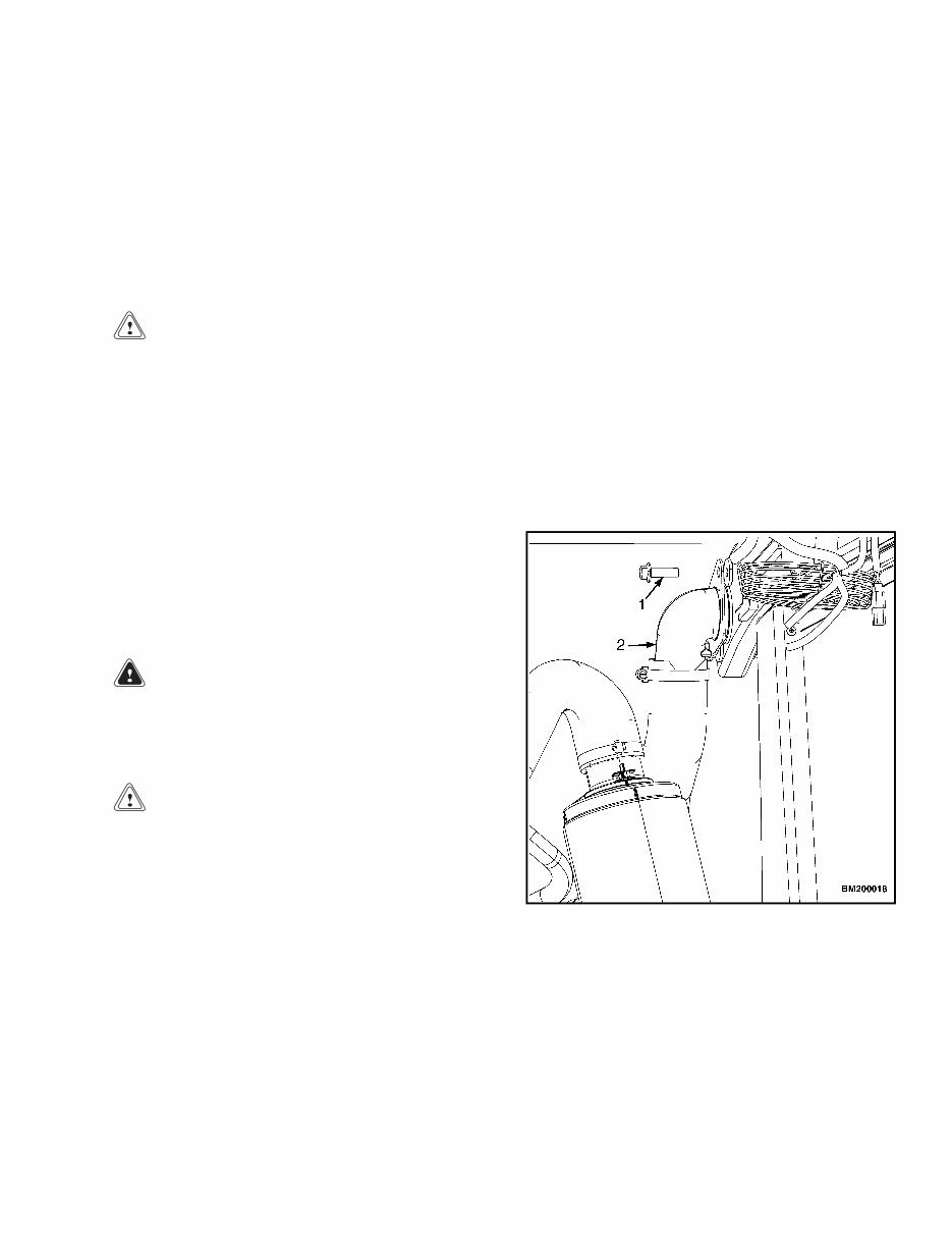
3. Disconnect the air filter hose from the rear left
corner leg of the cab frame. See Figure 4.
WARNING
DO NOT disconnect the heater hoses from the
engine when the engine is hot or when the cool-
ing system is under pressure, to do so could
cause serious injury.
WARNING
DO NOT remove the radiator cap from the ra-
diator when the engine is hot. When the radia-
tor is hot and the cap is removed, the pressure
is released from the system and the steam and
boiling coolant can cause burns. Wait 30 min-
utes for the engine to cool. Do a touch test by
2
100 SRM 1290 Cab Replacement
touching the radiator with your hand. If the
radiator is still hot to the touch, wait another
30 minutes before attempting to remove, check,
or fix any part of the cooling system.
NOTE: Removing the radiator cap will help depres-
surize the cooling system.
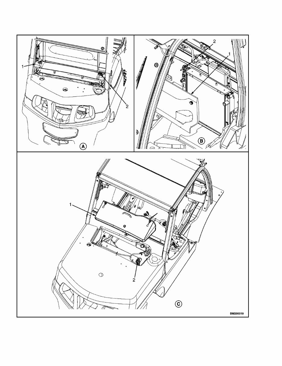
4. Remove radiator cover to access radiator cap. Re-
move radiator cap. See Figure 5.
CAUTION
Do not allow any fluid to drain when discon-
necting the heater hose from the engine. The
method will help when purging the system dur-
ing installation.
5. Disconnect and cap the heater hoses from engine.
See Figure 6.
NOTE: Removing the door assemblies requires two
people.
6. Open left side door, remove lock nut, and discon-
nect gas spring from the cab mounting bracket.
See Figure 7.
7. Lift left side door up and over hinge pin and set
aside. See Figure 8.
WARNING
DO NOT disconnect the heater hoses from the
quick disconnect fittings (inside operator cab)
or engine when the engine is hot or under pres-
sure, to do so could cause serious injury.
CAUTION
Disconnecting the right-hand gas spring and
fully opening the door without disconnecting
the heater hoses may cause the hoses to pull
loose from the quick disconnect fittings.
8. Disconnect heater hose quick disconnect fittings.
a. For Lift truck models H1.6FT, H1.8FT,
2.0FTS (F001), open right side door and
push the buttons on quick disconnect fit-
tings to disconnect the heater hoses from the
heater assembly hoses (see Figure 6). Dis-
connect the heater wire harness connection.
See Figure 9.
b. For lift truck models H2.0-3.5FT (H40-70FT)
(L177), open right side door and remove radi-
ator cover to access the quick disconnect fit-
tings. Push the buttons on the quick discon-
nect fittings to disconnect the heater hoses
from heater assembly (see Figure 6). Discon-
nect the heater wire harness connection. See
Figure 9.
c. For lift truck models H4.0FT5/FT6;
H4.5FTS5, H4.5FT6; H5.0-5.5FT (H80, 90,
100, 110, 120FT) (N005, P005), open right
side door and located on inner rear cover
there are two port holes (see Figure 6). Push
the buttons on the quick disconnect fittings
to disconnect the heater hoses from heater
assembly and disconnect the heater wire
harness connection. See Figure 9.
1. CAPSCREW
2. AIR FILTER HOSE
Figure 4. Air Filter Hose Removal
3
Cab Replacement 100 SRM 1290
Figure 5. Radiator Cover and Cap Location
4
You're Reading a Preview
What's Included?
 Lifetime Access
Fast Download Speeds
Online & Offline Access
Access PDF Contents & Bookmarks
Full Search Facility
Print one or all pages of your manual
$26.99
Hyster L177, N005, P005, H006, J006 Operator Cab Manual
Viewed 19 Times Today

What's Included?
Lifetime Access
Fast Download Speeds
Online & Offline Access
Access PDF Contents & Bookmarks
Full Search Facility
Print one or all pages of your manual
$26.99

Secure transaction
What's Included?
Lifetime Access
Fast Download Speeds
Online & Offline Access
Access PDF Contents & Bookmarks
Full Search Facility
Print one or all pages of your manual
Description
These manuals are designed to fit the following models:
- H1.6FT, H1.8FT, 2.0FTS [F001]
- H2.0-3.5FT (H40-70FT) [L177]
- H4.0FT5/FT6, H4.5FTS5, H4.5FT6
- H5.0-5.5FT(H80, 90, 100, 110, 120FT) [N005, P005]
- H6.0FT, H7.0FT (H135FT, H155FT) [H006, J006]


