SAFETY PRECAUTIONS MAINTENANCE AND REPAIR • When lifting parts or assemblies, make sure all slings, chains, or cables are correctly fastened, and that the load being lifted is balanced. Make sure the crane, cables, and chains have the capacity to support the weight of the load. • Do not lift heavy parts by hand, use a lifting mechanism. • Wear safety glasses. • DISCONNECT THE BATTERY CONNECTOR before doing any maintenance or repair on electric lift trucks. Disconnect the battery ground cable on internal combustion lift trucks. • Always use correct blocks to prevent the unit from rolling or falling. See HOW TO PUT THE LIFT TRUCK ON BLOCKS in the Operating Manual or the Periodic Mainte- nance section. • Keep the unit clean and the working area clean and orderly. • Use the correct tools for the job. • Keep the tools clean and in good condition. • Always use HYSTER APPROVED parts when making repairs. Replacement parts must meet or exceed the specifications of the original equipment manufacturer. • Make sure all nuts, bolts, snap rings, and other fastening devices are removed before using force to remove parts. • Always fasten a DO NOT OPERATE tag to the controls of the unit when making repairs, or if the unit needs repairs. • Be sure to follow the WARNING and CAUTION notes in the instructions. • Gasoline, Liquid Petroleum Gas (LPG), Compressed Natural Gas (CNG), and Diesel fuel are flammable. Be sure to follow the necessary safety precautions when handling these fuels and when working on these fuel systems. • Batteries generate flammable gas when they are being charged. Keep fire and sparks away from the area. Make sure the area is well ventilated. NOTE: The following symbols and words indicate safety information in this manual: WARNING Indicates a condition that can cause immediate death or injury! CAUTION Indicates a condition that can cause property damage!
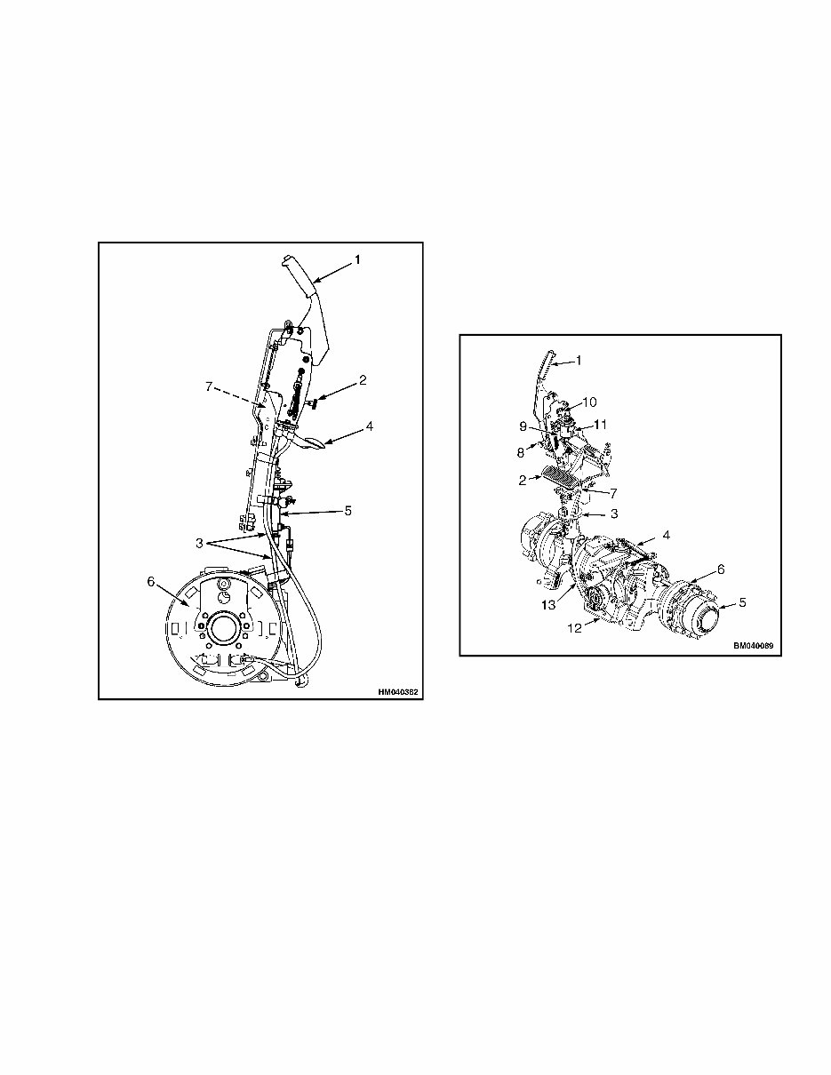
1800 SRM 1135 General General DRY BRAKE SYSTEM This section has service procedures for the dry brake system. The dry brake system includes the following parts: master cylinder, brake shoes, wheel cylinders, and parking brake system. 1. PARK BRAKE LEVER 2. ADJUSTMENT KNOB 3. PARK BRAKE CABLES 4. INCHING/BRAKE PEDAL 5. MASTER CYLINDER 6. BRAKE ASSEMBLY 7. BRAKE POSITION SENSOR (RIGHT HAND SIDE) Figure 1. Brake System WET BRAKE SYSTEM The wet brake system in this section includes the fol- lowing parts: master cylinder and parking brake sys- tem. See Figure 2. The wet disc brakes are a component of the wet brake drive axle. The brake discs are located inside the planetary carrier housing on the left side of the drive axle. See Drive Axle Repair, (Wet Brake) 1400 SRM 1215 for Remove, Assemble and Install proce- dures. See Figure 2. 1. PARK BRAKE HAND LEVER 2. INCH/BRAKE PEDAL 3. MASTER CYLINDER AND BOOSTER 4. PARK BRAKE LEVER 5. WET DISC BRAKE HOUSING 6. PLANETARY CARRIER HOUSING (RIGHT SIDE SHOWN) 7. BRAKE OIL SUPPLY HOSE 8. ADJUSTMENT KNOB 9. BRAKE POSITION SENSOR 10. BRAKE POSITION SENSOR CONNECTOR 11. BRAKE OIL RESERVOIR 12. PARKING BRAKE CABLE BRACKET 13. PARKING BRAKE CABLE Figure 2. Wet Brake System for Lift Truck Model H2.0-3.5FT (H40-70FT) (L177) 1
Service Brakes Repair (Dry Brake) 1800 SRM 1135 Service Brakes Repair (Dry Brake) REMOVE AND DISASSEMBLE WARNING Brake linings can contain dangerous fibers. Breathing the dust from these brake linings is a cancer or lung disease hazard. Do not create dust! Do not clean brake parts with compressed air or by brushing. Use vacuum equipment approved for brake dust or follow the cleaning procedure in this section. When the brake drums are removed, do not create dust. Do not sand, grind, chisel, hammer, or change linings in any way that will create dust. Any changes to brake linings must be done in a re- stricted area with special ventilation. Protec- tive clothing and a respirator must be used. 1. Remove the capscrews that hold the axle shaft to the hub. Remove the axle shaft. 2. See the procedure How to Put Lift Truck on Blocks in the section Periodic Maintenance 8000 SRM 1150, or the Operating Manual. Start the engine and tilt the mast fully back- ward. Put blocks under the mast. Tilt the mast forward until the wheels just touch the floor. Stop the engine. Put blocks under the frame of the lift truck. 3. Bend the lock plate and remove the nut that holds the axle bearing. Remove the washer and the bearing cone. WARNING When the brake shoes are removed, do not cre- ate dust in the air. See the Clean procedure in this section. 4. Put grease on the floor so that the wheel assem- bly will slide easily from the axle tube. Pull the wheel assembly from the lift truck. If the wheel assembly cannot be removed easily, use a small screwdriver to push the adjuster actuator away from the adjuster wheel. Use a brake adjustment tool or a screwdriver to turn the adjuster wheel to loosen the brake shoes. Remove the hub and drum assembly. Do not damage the grease seal when removing the hub. 5. Make a note of the arrangement of the parts. See Figure 3 and Figure 4 for S2.0-3.5FT (S40-70FT, S55FTS) [F187] and H2.0-3.5FT (H40-70FT) [L177] lift trucks. See Figure 5 and Figure 6 for S30FT, S35FT, S40FTS (E010) and H1.6FT, H1.8FT, H2.0FTS (H30FT, H35FT, H40FTS) [F001] lift trucks. Remove the return springs with spring pliers. 6. Remove the retainers, springs, and anchor pins that hold the brake shoes to the back plate. 7. Disengage the link from the adjuster wheel actu- ator. Remove the link, washer, and pivot plate. Remove the anchor guide. 8. Move the brake shoes away from each other to disengage the brake shoes from the wheel cylin- der. Disconnect the parking brake lever from the parking brake cable as the brake assembly is re- moved from the back plate. The parking brake lever has a hook that engages the parking brake cable. NOTE: The adjuster wheel for the left brake is not the same as the adjuster wheel for the right brake. The adjuster wheel for the left brake has left-hand threads. 9. Make a note of the arrangement of parts and dis- assemble the brake assembly. Remove the park- ing brake link and spring if they are still engaged with brake shoes. The parking brake link and spring will often fall from the brake assembly when the brake assembly is removed from the back plate. The adjuster wheel will also disen- gage from the brake shoes after the brake assem- bly is removed. 10. Remove the spring for the adjuster wheel actu- ator. Remove the adjuster wheel actuator from the brake shoe. 11. Use a screwdriver or small pry bar to move apart the ends of the retainer. Remove the spring washer and pivot pin to remove the parking brake lever from the brake shoe. 12. Disconnect the brake line from the wheel cylin- der. Remove the capscrews that hold the wheel cylinder to the back plate and remove the wheel cylinder. 2
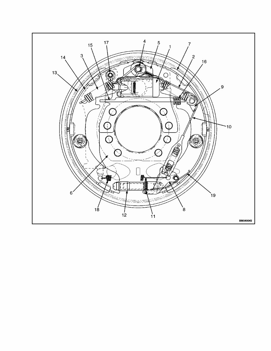
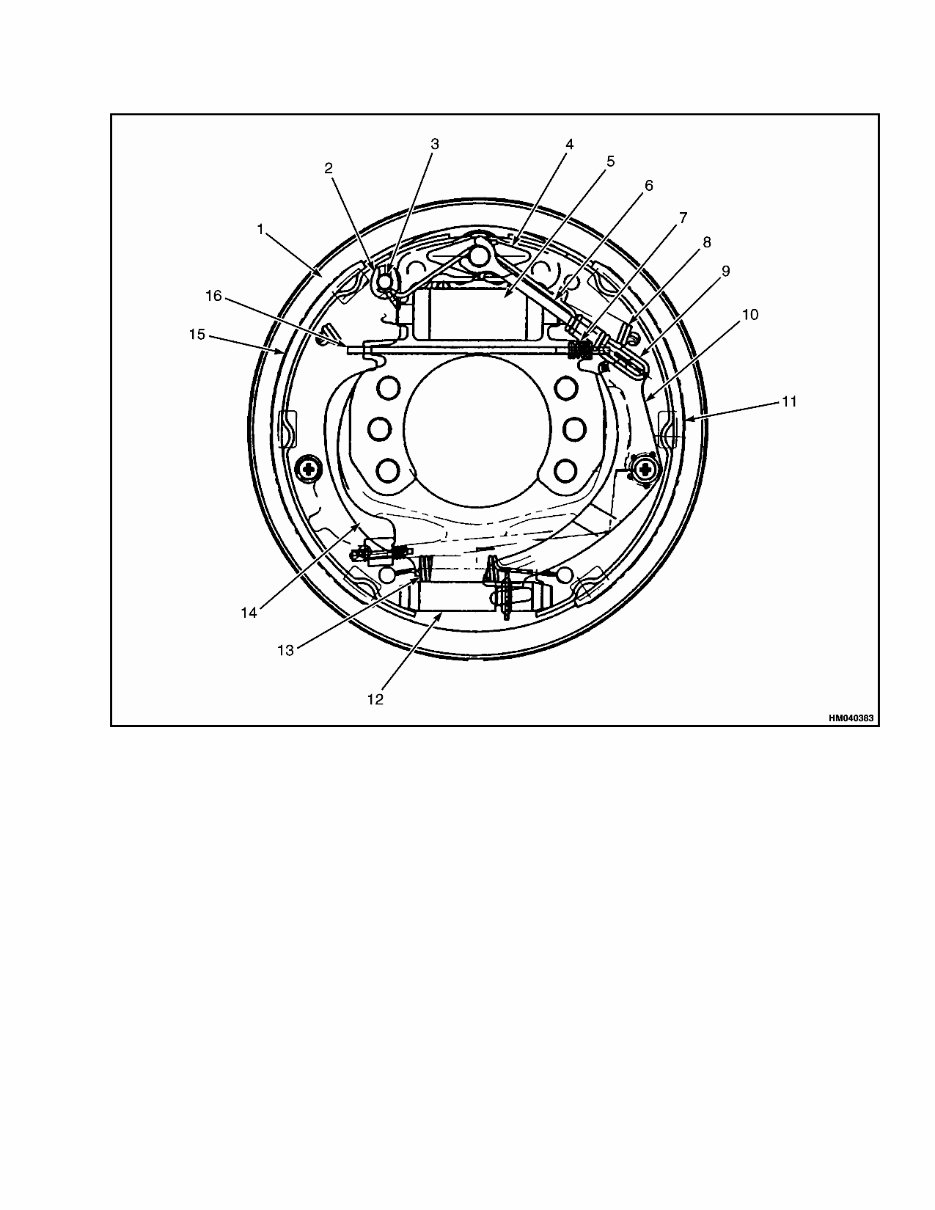
1800 SRM 1135 Service Brakes Repair (Dry Brake) 1. WHEEL CYLINDER 2. RETURN SPRING 3. RETURN SPRING 4. ANCHOR 5. ANCHOR GUIDE 6. BACK PLATE 7. SECONDARY BRAKE SHOE 8. LEVER 9. PIVOT PLATE 10. SPRING AND CABLE ASSEMBLY 11. ADJUSTER WHEEL 12. ADJUSTER ASSEMBLY 13. PRIMARY BRAKE SHOE 14. PARKING BRAKE LEVER 15. LINK, PARKING BRAKE 16. SPRING, PARKING BRAKE 17. PIVOT PIN, RETAINER, AND SPRING WASHER 18. ADJUSTER ACTUATOR SPRING 19. SPRING Figure 3. Brake Assembly (Left-Hand Shown), S2.0-3.5FT (S40-70FT, S55FTS) [F187] and H2.0-3.5FT (H40-70FT) [L177] 3
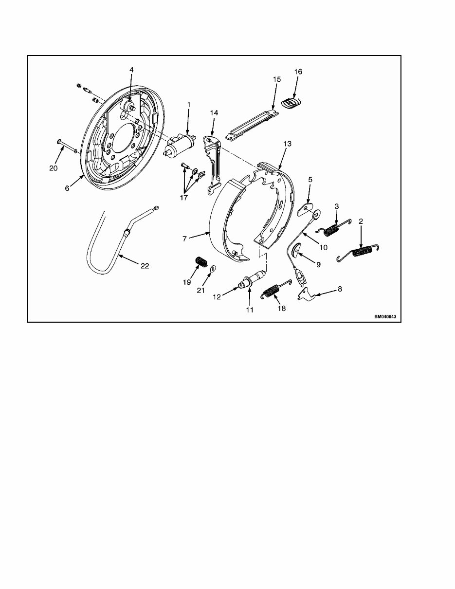
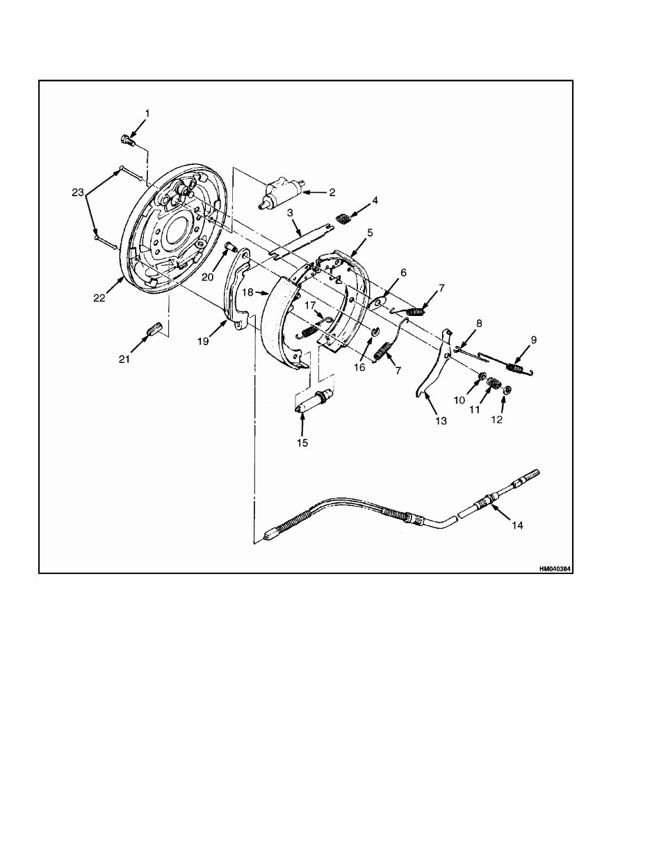
Service Brakes Repair (Dry Brake) 1800 SRM 1135 NOTE: RIGHT-HAND BRAKE ASSEMBLY SHOWN. 1. WHEEL CYLINDER 2. RETURN SPRING 3. RETURN SPRING 4. ANCHOR 5. ANCHOR GUIDE 6. BACK PLATE 7. SECONDARY BRAKE SHOE 8. LEVER 9. PIVOT PLATE 10. ADJUSTER ACTUATOR LINK 11. ADJUSTER WHEEL 12. ADJUSTER ASSEMBLY 13. PRIMARY BRAKE SHOE 14. PARKING BRAKE LEVER 15. PARKING BRAKE LINK 16. PARKING BRAKE SPRING 17. PIVOT PIN, RETAINER, AND SPRING WASHER 18. ADJUSTER ACTUATOR SPRING 19. SPRING 20. RETAINING PIN 21. RETAINING WASHER 22. PARKING BRAKE CABLE Figure 4. Service Brake Parts, S2.0-3.5FT (S40-70FT, S55FTS) [F187] and H2.0-3.5FT (H40-70FT) [L177] 4
1800 SRM 1135 Service Brakes Repair (Dry Brake) 1. BACKING PLATE 2. RETAINING RING 3. LEVER PIN 4. GUIDE PLATE 5. WHEEL CYLINDER 6. PAWL LEVER STOPPER 7. SPRING (ANTI-RATTLE) 8. RETURN SPRING 9. SPRING (ACTUATOR) 10. PAWL LEVER 11. SECONDARY BRAKE SHOE 12. ADJUSTER ASSEMBLY 13. ADJUSTER SPRING 14. PARK BRAKE LEVER 15. PRIMARY BRAKE SHOE 16. STRUT Figure 5. Brake Assembly (Left Hand Side), S30FT, S35FT, S40FTS (E010) and H1.6FT, H1.8FT, H2.0FTS (H30FT, H35FT, H40FTS) [F001] 5
Service Brakes Repair (Dry Brake) 1800 SRM 1135 1. BOLT 2. WHEEL CYLINDER 3. STRUT 4. SPRING 5. SECONDARY BRAKE SHOE 6. PLATE 7. SPRING 8. LEVER (STOP) 9. SPRING 10. WASHER 11. SPRING (SHOE HOLD DOWN) 12. WASHER 13. PAWL LEVER 14. PARK BRAKE CABLE 15. ADJUSTER ASSEMBLY 16. PLUG 17. SPRING (ADJUSTER) 18. PRIMARY BRAKE SHOE 19. PARK BRAKE LEVER 20. PIN 21. PLUG 22. BACKING PLATE 23. PIN Figure 6. Service Brake Parts, S30FT, S35FT, S40FTS (E010) and H1.6FT, H1.8FT, H2.0FTS (H30FT, H35FT, H40FTS) [F001] 6
Get your hands on the Hyster L177 (H2.0FT-H3.5FT Europe) Forklift Complete Workshop Service Repair Manual. This comprehensive manual is designed to cover every service and repair procedure you may need, making it an invaluable resource for both professional mechanics and DIY enthusiasts.
With easy-to-follow step-by-step instructions and detailed pictures, this manual empowers you to save money by performing your own repairs. You can conveniently access and utilize this manual indefinitely, whether in printed form, on your tablet, or on your smartphone.
All models, engines, trim, and transmission types are included in this manual, ensuring that it caters to a wide range of needs. From A to Z, this high-quality Service Repair Workshop Manual encompasses every repair and service procedure, providing comprehensive coverage.
Compatible with all PC and MAC computers, tablets, and mobile phones, this downloadable manual requires only Adobe Reader, which is commonly pre-installed. Upon payment via Visa, MasterCard, or PayPal, the manual will be promptly emailed to your specified address, ensuring instant delivery.
Rest assured, customer satisfaction is guaranteed with this manual, offering peace of mind as you delve into the world of forklift service and repair.
Recently Viewed
5,521,897Happy Clients
2,594,462eManuals
1,120,453Trusted Sellers
15Years in Business
Price:
Actual Price:
Hyster L177 (H2.0FT-H3.5FT Europe) Forklift Complete Workshop Service Repair Manual

 Forklift Complete Workshop Service Repair Manual")