


Calibration Procedures Table of Contents
TABLE OF CONTENTS
Description ......................................................................................................................................................... 1
Proc_Cal_001: Service Password Entry............................................................................................................ 4
When to Perform............................................................................................................................................ 4
Why Perform .................................................................................................................................................. 4
How to Perform.............................................................................................................................................. 4
Proc_Cal_002: Hydraulic Valve Calibration Warm Up and Air Bleed............................................................ 6
When to Perform............................................................................................................................................ 6
Calibration Order .......................................................................................................................................... 6
Why Perform .................................................................................................................................................. 6
How to Perform.............................................................................................................................................. 6
Proc_Cal_003: Save and Exit ............................................................................................................................ 8
When to Perform............................................................................................................................................ 8
Why Perform .................................................................................................................................................. 8
How to Perform.............................................................................................................................................. 8
Proc_Cal_004: Lift Valve Output Threshold .................................................................................................... 10
When to Perform............................................................................................................................................ 10
Calibration Order .......................................................................................................................................... 10
Why Perform .................................................................................................................................................. 10
How to Perform.............................................................................................................................................. 10
Proc_Cal_005: Lower Valve Output Threshold ................................................................................................ 12
When to Perform............................................................................................................................................ 12
Calibration Order .......................................................................................................................................... 12
Why Perform .................................................................................................................................................. 12
How to Perform.............................................................................................................................................. 12
Proc_Cal_006: Tilt Back Valve Output Threshold ........................................................................................... 16
When to Perform............................................................................................................................................ 16
Calibration Order .......................................................................................................................................... 16
Why Perform .................................................................................................................................................. 16
How to Perform.............................................................................................................................................. 16
Proc_Cal_007: Tilt Forward Valve Output Threshold ..................................................................................... 18
When to Perform............................................................................................................................................ 18
Calibration Order .......................................................................................................................................... 18
Why Perform .................................................................................................................................................. 18
How to Perform.............................................................................................................................................. 19
Proc_Cal_008: Aux 1 Dir A Valve Output Threshold....................................................................................... 22
When to Perform............................................................................................................................................ 22
Calibration Order .......................................................................................................................................... 22
Why Perform .................................................................................................................................................. 22
How to Perform.............................................................................................................................................. 22
Proc_Cal_009: Aux 1 Dir B Valve Output Threshold....................................................................................... 24
When to Perform............................................................................................................................................ 24
Calibration Order .......................................................................................................................................... 24
Why Perform .................................................................................................................................................. 24
How to Perform.............................................................................................................................................. 24
Proc_Cal_010: Aux 2 Dir A Valve Output Threshold....................................................................................... 28
When to Perform............................................................................................................................................ 28
Calibration Order .......................................................................................................................................... 28
Why Perform .................................................................................................................................................. 28
How to Perform.............................................................................................................................................. 28
Proc_Cal_011: Aux 2 Dir B Valve Output Threshold ....................................................................................... 30
When to Perform............................................................................................................................................ 30

Table of Contents Calibration Procedures
TABLE OF CONTENTS (Continued)
Calibration Order .......................................................................................................................................... 30
Why Perform .................................................................................................................................................. 30
How to Perform.............................................................................................................................................. 31
Proc_Cal_012: Aux 3 Dir A Valve Output Threshold....................................................................................... 34
When to Perform............................................................................................................................................ 34
Calibration Order .......................................................................................................................................... 34
Why Perform .................................................................................................................................................. 34
How to Perform.............................................................................................................................................. 34
Proc_Cal_013: Aux 3 Dir B Valve Output Threshold....................................................................................... 36
When to Perform............................................................................................................................................ 36
Calibration Order .......................................................................................................................................... 36
Why Perform .................................................................................................................................................. 36
How to Perform.............................................................................................................................................. 37
Proc_Cal_014: Load Weight Zero Point ............................................................................................................ 40
When to Perform............................................................................................................................................ 40
Calibration Order .......................................................................................................................................... 40
Why Perform .................................................................................................................................................. 40
How to Perform.............................................................................................................................................. 40
Proc_Cal_015: Loaded Weight Calibration....................................................................................................... 42
When to Perform............................................................................................................................................ 42
Calibration Order .......................................................................................................................................... 42
Why Perform .................................................................................................................................................. 42
How to Perform.............................................................................................................................................. 42
Proc_Cal_016: Transmission Valve Calibration ............................................................................................... 44
Applicable System/Option ............................................................................................................................. 44
When to Perform............................................................................................................................................ 44
Calibration Order .......................................................................................................................................... 44
Why Perform .................................................................................................................................................. 45
How to Perform.............................................................................................................................................. 45
Applicable System/Option ............................................................................................................................. 46
When to Perform............................................................................................................................................ 46
Calibration Order .......................................................................................................................................... 46
Why Perform .................................................................................................................................................. 46
How to Perform.............................................................................................................................................. 46
Proc_Cal_016A: Transmission Valve Calibration-Electronic Extended Function .......................................... 48
Applicable System/Option ............................................................................................................................. 48
When to Perform............................................................................................................................................ 48
Calibration Order .......................................................................................................................................... 48
Why Perform .................................................................................................................................................. 48
How to Perform.............................................................................................................................................. 48
Proc_Cal_016B: Trans. Valve Calibration-Electronic and Electronic Extended Function ............................ 50
Applicable System/Option ............................................................................................................................. 50
When to Perform............................................................................................................................................ 50
Calibration Order .......................................................................................................................................... 50
Why Perform .................................................................................................................................................. 50
How to Perform.............................................................................................................................................. 50
Proc_Cal_019: Mazda LP and Gas Accelerator Pedal Adjustment ................................................................. 52
Required Tools................................................................................................................................................ 52
When to Perform............................................................................................................................................ 52
Calibration Order .......................................................................................................................................... 52
Why Perform .................................................................................................................................................. 52

Calibration Procedures Table of Contents
TABLE OF CONTENTS (Continued)
How to Perform.............................................................................................................................................. 52
Proc_Cal_025: Hydraulic Valve Pressure Gage Installation ........................................................................... 54
When to Perform............................................................................................................................................ 54
Why Perform .................................................................................................................................................. 54
How to Perform.............................................................................................................................................. 54
Proc_Cal_026: Travel Speed Calibration .......................................................................................................... 56
When to Perform............................................................................................................................................ 56
Calibration Order .......................................................................................................................................... 56
Why Perform .................................................................................................................................................. 56
How to Perform.............................................................................................................................................. 56
This section is for the following models:
S30FT, S35FT, S40FTS [E010];
H1.6FT, H1.8FT, H2.0FTS (H30FT, H35FT, H40FTS) [F001];
S2.0-3.5FT (S40-70FT, S55FTS ) [F187];
S4.0, 4.5, 5.5FT, S5.5FTS (S80, 100, 120FT; S80, 100FTBCS;
S120FTS; S120FTPRS) [G004];
H2.0-3.5FT (H40-70FT) [L177];
H4.0FT5/FT6; H4.5FTS5, H4.5FT6; H5.0-5.5FT (H80, 90, 100,
110, 120FT) [N005, P005];
H6.0FT, H7.0FT; (H135FT, H155FT) [H006, J006];
S6.0FT, S7.0FT, (S135FT,S155FT) [D024, E024]

8000 SRM 1134 Description
Description
This section is written assuming no experience with
electronic controllers. The menu progressions indi-
cate how many key presses it will take to get to a
given screen, versus detailing out every screen you
would see. Refer to Table 1 for calibration proce-
dures. Refer to Table 2 for an example of how to read
calibration procedures.
NOTE: The calibration procedures described in this
SRM may have to be repeated when any on-board
controllers, sensors, or related components are re-
placed.
Table 1. Calibration Procedures
When Procedure is Used:
Proc_Cal/Procedure All
Units
3
Functions
Electronic-
Hydraulic
Valves
4
Functions
Electronic-
Hydraulic
Valves
5
Functions
Electronic-
Hydraulic
Valves
Mazda Engine
w/Electronic
1-Speed
Transmission
Units
w/Load
Weight
Display
Electronic
Transmission
(Basic & L1)
Electronic
Extended
Function
2-Speed
(L2-2)
001 Service Password Entry X
002 Hydraulic Valve
Calibration Warm Up and
Air Bleed
X X X
003 Save and Exit X
004 Lift Valve Output
Threshold
X X X
005 Lower Valve Output
Threshold
X X X
006 Tilt Back Valve Output
Threshold
X X X
007 Tilt Forward Valve
Output Threshold
X X X
008 Aux 1 Dir A Valve Output
Threshold
X X X
009 Aux 1 Dir B Valve Output
Threshold
X X X
010 Aux 2 Dir A Valve Output
Threshold
X X
011 Aux 2 Dir B Valve Output
Threshold
X X
012 Aux 3 Dir A Valve Output
Threshold
X
013 Aux 3 Dir B Valve Output
Threshold
X
014 Load Weight Zero Point X
015 Loaded Weight
Calibration
X
016 Transmission Valve
Calibration (Basic & L1)
X
016A Transmission Valve
Calibration (L2)
X
019 Mazda LP and
Gas Acceleration Pedal
Adjustment
X
Description 8000 SRM 1134
Table 1. Calibration Procedures (Continued)
When Procedure is Used:
Proc_Cal/Procedure All
Units
3
Functions
Electronic-
Hydraulic
Valves
4
Functions
Electronic-
Hydraulic
Valves
5
Functions
Electronic-
Hydraulic
Valves
Mazda Engine
w/Electronic
1-Speed
Transmission
Units
w/Load
Weight
Display
Electronic
Transmission
(Basic & L1)
Electronic
Extended
Function
2-Speed
(L2-2)
025 Hydraulic Valve Pressure
Gage Installation
X X X
026 Travel Speed Calibration X X
Table 2. How to Read Calibration Procedure
Proc_Cal_XXX Number and title of calibration procedure.
Calibration Order Calibration procedures that must be completed before this
procedure, if any.
When to Perform Performed either during initial manufacture or after
component changes.
Why Perform Description of why the procedure is performed.
Proc_Cal_001: Service Password Entry
Proc_Cal_002: Hydraulic Valve Calibration
Warm Up
Calibration procedures that must be completed before this
procedure, if any.
Action Actions to perform other than calibration steps. Numbered
when needed for clarification.
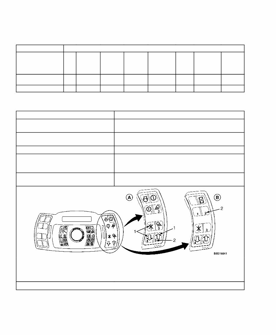
A. TYPICAL DISPLAY WITHOUT KEY,
WITH OPTIONS
B. TYPICAL DISPLAY WITH KEY,
WITHOUT OPTIONS
1. SYMBOLS USED IN CALIBRATION
PROCEDURES
2. NUMBERS FOR SERVICE PASSWORD ENTRY -
SEE PROC_CAL_001
NOTE: Perform all actions and calibration steps in the order shown.

8000 SRM 1134 Description
Table 2. How to Read Calibration Procedure (Continued)
Step 1: Press * One Time
You will see:
Passwords
Enter Password
Step 2: Press * One Time
You will see:
Enter Password
Calibration steps.
Information Information to assist in completion of calibration procedure.
NOTE: Perform all actions and calibration steps in the order shown.

Proc_Cal_001: Service Password Entry 8000 SRM 1134
Proc_Cal_001: Service Password Entry
WHEN TO PERFORM
Performed when any service menu-related items
must be performed.
WHY PERFORM
Service-related items are protected from inadvertent
access. This procedure allows the service menus to
be accessed.
HOW TO PERFORM
WARNING
Keep yourself and all others clear of the lift
mechanism. Never allow anyone under or on
the forks.
Never put hands, arms, head, or legs through
the mast or near the carriage or lift chains.
This warning applies not only to the opera-
tor but also the helper. A helper must not be
near the load or the lift mechanism while the
operator is attempting to handle a load. The
lift mechanism has moving parts with close
clearances that can cause serious injury.
Refer to Table 3 for the procedures on how to perform
Pro_Cal_001: Service Password Entry.
8000 SRM 1134 Proc_Cal_001: Service Password Entry
Table 3. Proc_Cal_001: Service Password Entry
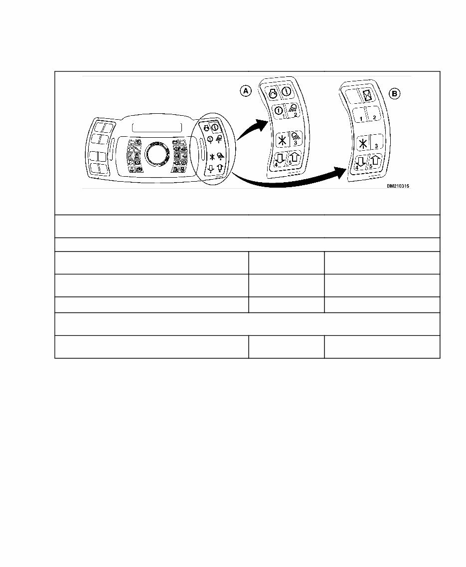
A. TYPICAL DISPLAY WITHOUT KEY, WITH OPTIONS
B. TYPICAL DISPLAY WITH KEY, WITHOUT OPTIONS
NOTE: The password entry can only be done with the ignition ON and the engine OFF. If the engine is
started, and then turned OFF, the password will have to be re-entered.
Action: Ignition ON/EngineOFF
Step 1: Press * One Time.
You Will See: Main Menu
Passwords
Step 2: Press * One Time.
You Will See: Passwords
Enter Password
Step 3: Press * One Time.
You Will See: Enter Password
Information: Refer to Number Location on Keypad and Enter Service Password (Default Service
Password is 55555).
Step 4: Press * One Time.
You Will See: Passwords or Main Menu
Enter Password
Proc_Cal_002: Hydraulic Valve Calibration Warm Up and Air Bleed 8000 SRM 1134
Proc_Cal_002: Hydraulic Valve Calibration Warm Up and Air Bleed
WHEN TO PERFORM
Performed when any hydraulic calibration items are
performed.
CALIBRATION ORDER
1. Proc_Cal_025
2. Proc_Cal_001
3. Proc_Cal_002
WHY PERFORM
Hydraulic calibrations are the process of setting the
hydraulic current levels that result in initial function
movement. Pressure and flow are directly related to
the hydraulic fluid viscosity which is a function of the
fluid temperature. Air, trapped within the lift valve
assembly, may produce slight mast movement at
engine start. This process ensures that the hydraulic
fluid achieves an optimum temperature, and that the
air is bled out of the lift valve and cylinders prior to
performing calibrations.
HOW TO PERFORM
WARNING
Keep yourself and all others clear of the lift
mechanism. Never allow anyone under or on
the forks.
Never put hands, arms, head, or legs through
the mast or near the carriage or lift chains.
This warning applies not only to the opera-
tor but also the helper. A helper must not be
near the load or the lift mechanism while the
operator is attempting to handle a load. The
lift mechanism has moving parts with close
clearances that can cause serious injury.
Refer to Table 4 for the procedures on how to perform
Proc_Cal_002: Hydraulic Valve Calibration Warm
Up and Air Bleed.
Table 4. Proc_Cal_002: Hydraulic Valve Calibration Warm Up and Air Bleed

8000 SRM 1134 Proc_Cal_002: Hydraulic Valve Calibration Warm Up and Air Bleed
Table 4. Proc_Cal_002: Hydraulic Valve Calibration Warm Up and Air Bleed (Continued)
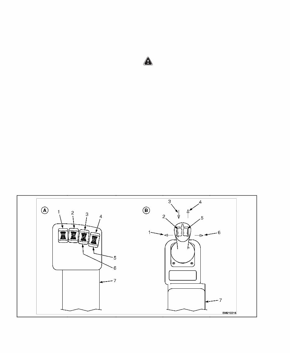
A. E-HYD CONTROL LEVERS
1. LIFT/LOWER
DIRECTION LIFT ↓
DIRECTION LOWER ↑
2. TILT
DIRECTION BACK ↓
DIRECTION FWD ↑
3. *AUX 1 OR AUX 2
DIRECTION A ↑
DIRECTION B ↓
4. *AUX 2 OR AUX 3
DIRECTION A ↑
DIRECTION B ↓
5. *FOURTH LEVER
6. *THIRD LEVER
7. SEAT ARMREST
*AUX 2 IS IN THE FOURTH LEVER LOCATION EXCEPT AS FOLLOWS: WITH 5 FUNCTION VALVE WITH CLAMPING ATTACHMENT, AUX
2 IS IN THE THIRD LEVER LOCATION.
B. JOYSTICK
1. TILT BACK 2. AUX 1
DIRECTION A ↑
DIRECTION B ↓
3. LIFT ↓
4. ↑ LOWER
5. AUX 2
DIRECTION A ↑
DIRECTION B ↓
6. TILT FORWARD
7. SEAT ARMREST
Perform Proc_Cal_025: Hydraulic Valve Pressure Gage Installation and Proc_Cal_001: Service
Password Entry before proceeding.
Information: First determine if it is necessary to bleed the air out of the lift valve and cylinders. The hoist
valve air bleed procedure is necessary if the carriage moves slightly (approximately 1/4 inch) when the
engine is started, without activation of the lift control. The cylinder air bleed procedure is necessary if the
cylinders have not been previously cycled, or if the left function is not operating smoothly.
NOTE: Optional for initial manufacture.
Information: To ensure that the oil temperature is optimal, warm up the hydraulic fluid until it is within a
range of 50 to 65 C (12 to 149 F).
Action:
• Ignition: ON
• Engine: High Idle
• Transmission: Neutral
• Park Brake: ON
Step 1: (Optional hoist valve air bleed): Activate Lift Control from neutral to full lift and back to neutral
at a rate of one or two times per second. Repeat until the lift function is operating smoothly and there is no
mast movement upon engine start.
Step 2: (Optional cylinder air bleed): Cycle function completely two or three times; repeat if necessary.
NOTE: Optional for initial manufacture.
Step 3: (Required warm up for service): Activate tilt at relief pressure until the hydraulic fluid temperature
is within the optimum range 50 to 65 C (12 to 149 F).
Step 4: Proceed to calibrate desired electro-hydraulic functions.
Information: You do not need to START or turn OFF the vehicle if you are performing other procedures.
You're Reading a Preview
What's Included?
Fast Download Speeds
Online & Offline Access
Access PDF Contents & Bookmarks
Full Search Facility
Print one or all pages of your manual
$27.99
$36.99
Hyster Forklift Calibration Procedures Manual
Viewed 17 Times Today

What's Included?
Fast Download Speeds
Online & Offline Access
Access PDF Contents & Bookmarks
Full Search Facility
Print one or all pages of your manual
$27.99
$36.99

Secure transaction
What's Included?
Fast Download Speeds
Online & Offline Access
Access PDF Contents & Bookmarks
Full Search Facility
Print one or all pages of your manual
These digital manuals are designed to fit the following models:
- S30FT, S35FT, S40FTS [E010]
- H1.6FT, H1.8FT, H2.0FTS (H30FT, H35FT, H40FTS) [F001]
- S2.0-3.5FT(S40-70FT, S55FTS ) [F187]
- S4.0, 4.5,5.5FT, S5.5FTS (S80, 100, 120FT; S80, 100FTBCS;S120FTS; S120FTPRS) [G004]
- H2.0-3.5FT (H40-70FT) [L177]
- H4.0FT5/FT6; H4.5FTS5, H4.5FT6
- H5.0-5.5FT (H80, 90, 100, 110, 120FT) [N005, P005]
- H6.0FT, H7.0FT; (H135FT, H155FT) [H006, J006]
- S6.0FT, S7.0FT, (S135FT,S155FT) [D024, E024]


