SAFETY PRECAUTIONS MAINTENANCE AND REPAIR • When lifting parts or assemblies, make sure all slings, chains, or cables are correctly fastened, and that the load being lifted is balanced. Make sure the crane, cables, and chains have the capacity to support the weight of the load. • Do not lift heavy parts by hand, use a lifting mechanism. • Wear safety glasses. • DISCONNECT THE BATTERY CONNECTOR before doing any maintenance or repair on electric lift trucks. • Disconnect the battery ground cable on internal combustion lift trucks. • Always use correct blocks to prevent the unit from rolling or falling. See HOW TO PUT THE LIFT TRUCK ON BLOCKS in the Operating Manual or the Periodic Mainte- nance section. • Keep the unit clean and the working area clean and orderly. • Use the correct tools for the job. • Keep the tools clean and in good condition. • Always use HYSTER APPROVED parts when making repairs. Replacement parts must meet or exceed the specifications of the original equipment manufacturer. • Make sure all nuts, bolts, snap rings, and other fastening devices are removed before using force to remove parts. • Always fasten a DO NOT OPERATE tag to the controls of the unit when making repairs, or if the unit needs repairs. • Be sure to follow the WARNING and CAUTION notes in the instructions. • Gasoline, Liquid Petroleum Gas (LPG), Compressed Natural Gas (CNG), and Diesel fuel are flammable. Be sure to follow the necessary safety precautions when handling these fuels and when working on these fuel systems. • Batteries generate flammable gas when they are being charged. Keep fire and sparks away from the area. Make sure the area is well ventilated. NOTE: The following symbols and words indicate safety information in this manual: WARNING Indicates a condition that can cause immediate death or injury! CAUTION Indicates a condition that can cause property damage!
Table of Contents Perkins Diesel Engines TABLE OF CONTENTS (Continued) Engine Speed Control Assembly ................................................................................................................... 57 Remove ....................................................................................................................................................... 57 Replace ....................................................................................................................................................... 58 Install ......................................................................................................................................................... 58 Fuel Injection Pump Linkage........................................................................................................................ 58 Remove ....................................................................................................................................................... 58 Fuel Control Lever, Replace...................................................................................................................... 59 Governor Control Lever, Replace.............................................................................................................. 59 Install ......................................................................................................................................................... 60 Record Maximum Fuel Position.................................................................................................................... 61 Record Maximum Fuel Position of Fuel Rack ......................................................................................... 61 Set Adjustment Screw for Maximum Fuel Setting ................................................................................. 62 Electrical Stop Solenoid ................................................................................................................................ 63 Remove ....................................................................................................................................................... 63 Install ......................................................................................................................................................... 64 Cooling System Repair ...................................................................................................................................... 64 Description ..................................................................................................................................................... 64 Thermostat, Replace ...................................................................................................................................... 64 Coolant Pump ................................................................................................................................................ 64 Remove ....................................................................................................................................................... 64 Install ......................................................................................................................................................... 65 Fan.................................................................................................................................................................. 65 Remove ....................................................................................................................................................... 65 Install ......................................................................................................................................................... 65 Flywheel and Housing Repair ........................................................................................................................... 65 Description ..................................................................................................................................................... 65 Flywheel ......................................................................................................................................................... 65 Remove ....................................................................................................................................................... 65 Install ......................................................................................................................................................... 65 Ring Gear, Replace ........................................................................................................................................ 66 Flywheel Housing .......................................................................................................................................... 66 Remove ....................................................................................................................................................... 66 Install ......................................................................................................................................................... 66 Electrical System Repair ................................................................................................................................... 66 Drive Belt ....................................................................................................................................................... 66 Alternator....................................................................................................................................................... 67 Remove ....................................................................................................................................................... 67 Install ......................................................................................................................................................... 67 Starter Motor ................................................................................................................................................. 68 Remove ....................................................................................................................................................... 68 Install ......................................................................................................................................................... 68 Glow Plugs ..................................................................................................................................................... 68 Remove ....................................................................................................................................................... 68 Continuity Check....................................................................................................................................... 68 Operation Check ........................................................................................................................................ 68 Install ......................................................................................................................................................... 69 Engine Specifications ......................................................................................................................................... 69 Cylinder Head Assembly ............................................................................................................................... 69 Piston and Connecting Rods ......................................................................................................................... 71 Crankshaft Assembly .................................................................................................................................... 73 Crankshaft Heat Treatment ..................................................................................................................... 73 iv
Perkins Diesel Engines Table of Contents TABLE OF CONTENTS (Continued) Crankshaft Overhaul ................................................................................................................................ 73 Timing Case and Gear Assembly .................................................................................................................. 75 Engine Block Assembly ................................................................................................................................. 76 Timing Data ................................................................................................................................................... 76 Lubrication System ....................................................................................................................................... 76 Fuel System ................................................................................................................................................... 77 Cooling System .............................................................................................................................................. 77 Electrical Equipment..................................................................................................................................... 78 Torque Specifications ......................................................................................................................................... 79 Cylinder Head Assembly ............................................................................................................................... 79 Piston and Connecting Rod Assemblies ....................................................................................................... 79 Crankshaft Assembly .................................................................................................................................... 79 Timing Case and Drive Assembly ................................................................................................................. 79 Lubrication System ....................................................................................................................................... 79 Fuel System ................................................................................................................................................... 79 Cooling System .............................................................................................................................................. 80 Flywheel ......................................................................................................................................................... 80 Valve Cover .................................................................................................................................................... 80 Electrical Equipment..................................................................................................................................... 80 Special Tools ....................................................................................................................................................... 81 This section is for the following models: H2.00-3.20XM (H40-65XM) [D177, H177] v
"THE QUALITY KEEPERS" HYSTER APPROVED PARTS
600 SRM 706 General Safety Rules Description This section has the description and the repair pro- cedures for the Perkins diesel 704-26 (Model UB) en- gine. Disassembly, cleaning, assembly procedures, Engine Specifications, and Torque Specifications are included in this section. The end of the engine with the fan is the front of the engine. Model UB is a 2.6-liter, four-cylinder, liquid-cooled engine. This diesel engine uses indirect fuel injec- tion. An indirect fuel injection engine has a small precombustion chamber in the cylinder head. This precombustion chamber permits ignition of a normal fuel-to-air ratio which then expands into a less than normal fuel-to-air-air ratio of the combustion cham- ber in the piston head. This combustion process de- creases smoke and possible harmful emissions from the engine exhaust. This engine has a closed crankcase ventilation sys- tem (breather system). Exhaust gases generated in the crankcase and cylinder head spaces during engine operation are returned to the combustion chambers through the air induction system. The cast-iron cylinder block is made without cylin- der liners. The crankshaft is induction hardened and has five main bearings. The end clearance of the crankshaft is controlled by two half thrust washers installed on each side of the number four main bear- ing. Each piston has two compression rings and an oil control ring. Each piston and connecting rod is matched to its cylinder. The correct piston height is obtained during engine assembly by careful selection of one of six possible lengths of connecting rods. The cylinder head has two valves per cylinder. There is a valve guide and a valve seat for each valve. Each valve has a single valve spring and an oil seal in- stalled on top of the valve guide. The face angle for all of the valves is 45 degrees and the angle for all of the valve seats is 45 degrees. The bottom face of the cylinder head cannot be machined because of the precombustion chamber. General Safety Rules WARNING Viton Seals Some seals used in this engine are made of a synthetic material called Viton. Viton is a safe material when used under normal conditions of operation. If Viton is burned, a dangerous acid is pro- duced as a byproduct. Never permit burned material to come into contact with the skin or the eyes. If it is necessary to handle components that have been burned, use the following proce- dures: • Make sure the components are cool. • Use neoprene gloves and discard the gloves after use. • Wash the area with calcium hydroxide solu- tion and then clean with water. • Discard the components and gloves in accor- dance with environmental regulations. Burned Viton byproduct that touches the skin or eyes must be immediately flushed with wa- ter or a calcium hydroxide solution. Get medi- cal help immediately. WARNING Disconnect the battery cables before doing any disassembly and repair of the engine or parts of the electrical system. Put a DO NOT OPERATE tag in the operator’s area and on the battery connectors. Long-term exposure to used engine oil can cause skin irritation or cancer. Wash with detergent and water. Exhaust from internal combustion engines contains carbon monoxide and other harmful chemicals. Carbon monoxide is a colorless, odorless poison and can cause unconscious- ness or death without warning. Long-term exposure to exhaust or chemicals in the ex- haust can cause cancer, birth defects, and other reproductive harm. Avoid exposure to engine exhaust. 1
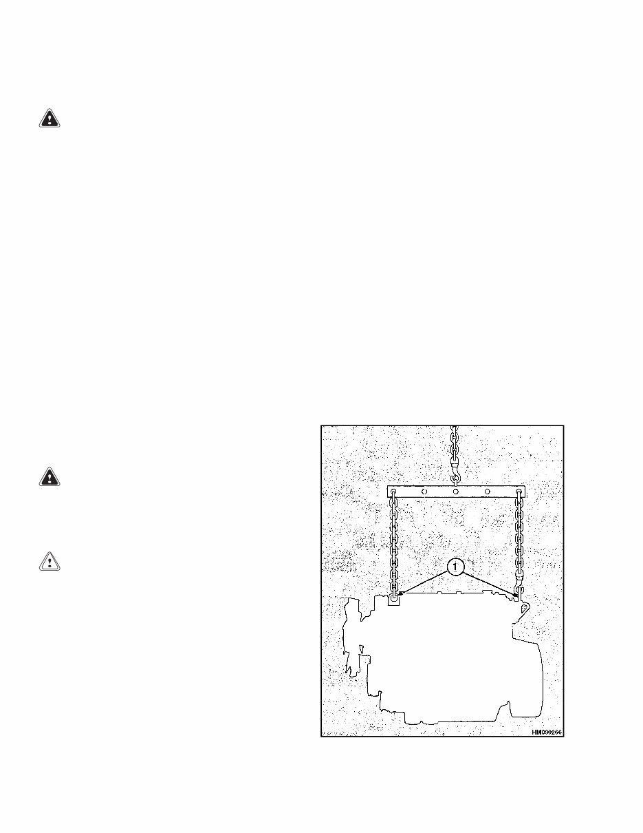
Engine Removal and Installation 600 SRM 706 Do not use diesel engines indoors where soot can accumulate. WARNING If engines are operated in confined spaces, maintain adequate ventilation or vent exhaust to the outside. Do not exceed applicable air contaminant limits. Follow the inspection and maintenance sched- ule and procedures in this manual. Do not alter exhaust, ignition, or fuel systems. Disposal of batteries must meet local environ- mental regulations. The diodes and resistors in the electrical sys- tem can be damaged if the following cautions are not followed: • Do not disconnect the battery when the en- gine is running. The voltage surge can dam- age the diodes and resistors. • Do not disconnect an electric wire before the engine is stopped and the switches are OFF. • Do not cause a short circuit by connection of the electric wires to the wrong terminals. Make sure a correct identification is made of a wire before it is connected. • Make sure a battery is the correct voltage and polarity before it is connected. • Do not check for current flow by mak- ing a spark because the diodes and other solid-state components can be damaged. Please observe the previous warnings before working on engine. Engine Removal and Installation GENERAL See Frame section for the procedure for removing the engine and transmission. See Transmission section for the procedure to separate the transmis- sion from the engine. LIFTING ENGINE WARNING A complete engine weighs approximately 300 kg (700 lb). Use a lifting device that has a minimum capacity of 500 kg (1100 lb) when a complete engine assembly must be moved. CAUTION Disposal of lubricants and fluids must meet lo- cal environmental regulations. Before an engine is lifted: • Make sure the lifting equipment has the correct capacity to lift the engine. Use a vertical lift as shown in Figure 1. Never use a single lift bracket to lift an engine. • Make sure the engine lift brackets are in good con- dition and correctly fastened to the engine. The capscrews for the engine brackets are tightened to 22 N•m (195 lbf in). • Make sure lifting slings do not damage the valve cover or other engine components. • Some components of the engine assembly are heavy. Always use a lifting device when moving the cylinder bock, cylinder head, flywheel housing, crankshaft, and flywheel. Figure 1. Lifting Engine 2 A HM090266
This Complete Service Repair Workshop Manual for the Hyster Challenger H177 H45xm, H50xm, H55xm, H60xm, H65xm Forklift is an invaluable resource for both professional mechanics and DIY enthusiasts.
DESCRIPTION:
This manual provides easy-to-follow, step-by-step instructions and pictures for all servicing and repair procedures, enabling you to save money by performing your own repairs. Once downloaded, the manual is yours to keep forever, allowing you to print individual pages, chapters, or the entire manual. It can also be saved to your tablet or smartphone for easy access.
MODELS COVERED:
All Models/Engines/Trim/Transmissions Types Are Covered.
CONTENTS:
This high-quality Service Repair Workshop Manual covers all repair procedures from A to Z, ensuring that every repair and service procedure is comprehensively addressed.
COMPUTER REQUIREMENTS:
This downloadable Manual is compatible with all PC & MAC Computers, tablets, and mobile phones. The only software required is Adobe Reader, which is typically pre-installed on most computers or can be downloaded for free.
INSTANT DELIVERY:
Upon payment by Visa, MasterCard, or PayPal, the manual will be instantly emailed to the address provided during checkout.