SAFETY PRECAUTIONS MAINTENANCE AND REPAIR • When lifting parts or assemblies, make sure all slings, chains, or cables are correctly fastened, and that the load being lifted is balanced. Make sure the crane, cables, and chains have the capacity to support the weight of the load. • Do not lift heavy parts by hand, use a lifting mechanism. • Wear safety glasses. • DISCONNECT THE BATTERY CONNECTOR before doing any maintenance or repair on electric lift trucks. • Disconnect the battery ground cable on internal combustion lift trucks. • Always use correct blocks to prevent the unit from rolling or falling. See HOW TO PUT THE LIFT TRUCK ON BLOCKS in the Operating Manual or the Periodic Mainte- nance section. • Keep the unit clean and the working area clean and orderly. • Use the correct tools for the job. • Keep the tools clean and in good condition. • Always use HYSTER APPROVED parts when making repairs. Replacement parts must meet or exceed the specifications of the original equipment manufacturer. • Make sure all nuts, bolts, snap rings, and other fastening devices are removed before using force to remove parts. • Always fasten a DO NOT OPERATE tag to the controls of the unit when making repairs, or if the unit needs repairs. • Be sure to follow the WARNING and CAUTION notes in the instructions. • Gasoline, Liquid Petroleum Gas (LPG), Compressed Natural Gas (CNG), and Diesel fuel are flammable. Be sure to follow the necessary safety precautions when handling these fuels and when working on these fuel systems. • Batteries generate flammable gas when they are being charged. Keep fire and sparks away from the area. Make sure the area is well ventilated. NOTE: The following symbols and words indicate safety information in this manual: WARNING Indicates a condition that can cause immediate death or injury! CAUTION Indicates a condition that can cause property damage!
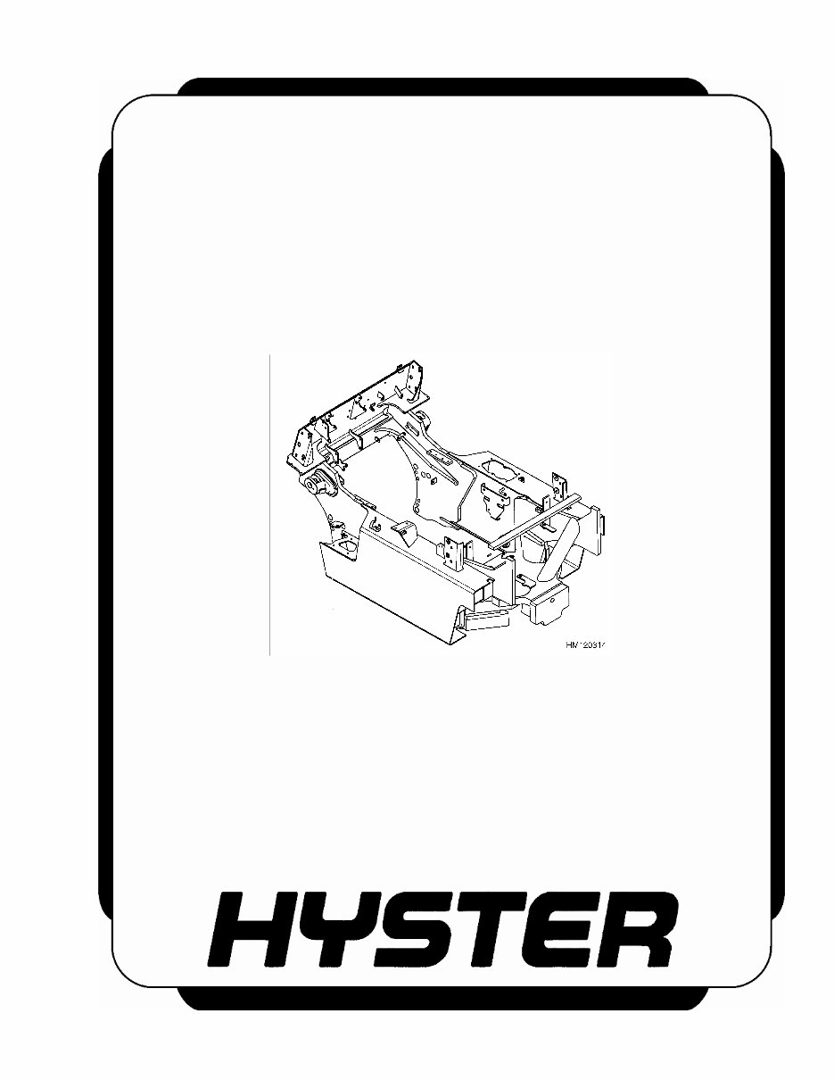
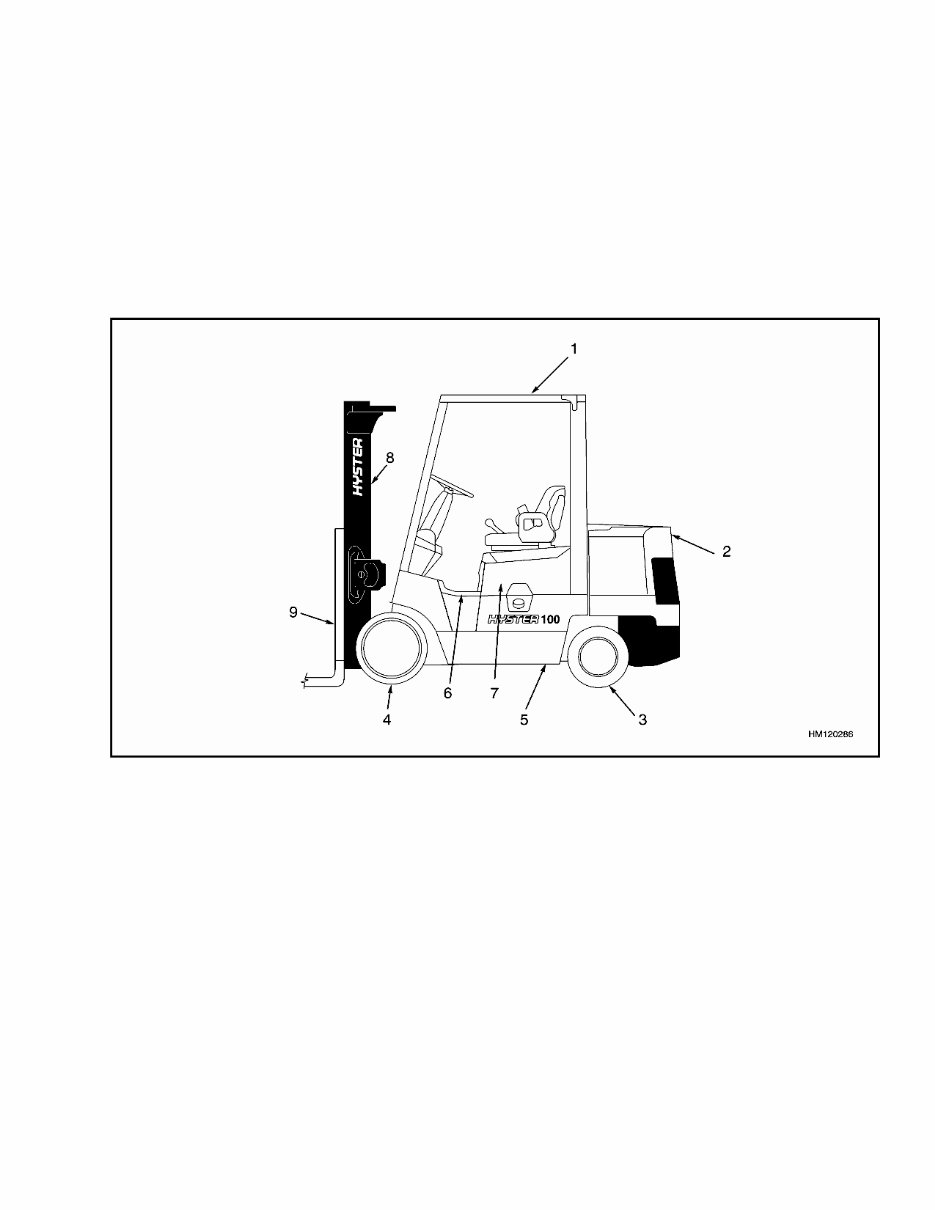
100 SRM 981 Description Description The frame is one weldment and includes the hy- draulic tank and fuel tank for gasoline or diesel fuel. Liquefied petroleum gas (LPG) tanks are mounted behind the seat on top of the counterweight. There is a counterweight for each capacity of lift truck. The counterweights are similar, but are dif- ferent weights. The muffler is fastened to the frame inside of the counterweight. An overhead guard is fastened to the cowl at the front of the lift truck and to a frame plate at the rear of the lift truck. The hood is connected to the frame plate with hinges. A gas-controlled spring gives assistance when raising the hood and holds the hood in the open position. The floor plates can be removed for access to the trans- mission and other components. See Figure 1. 1. OVERHEAD GUARD 2. COUNTERWEIGHT 3. STEER AXLE 4. DRIVE AXLE 5. FRAME 6. FLOOR PLATE 7. HOOD 8. MAST 9. CARRIAGE Figure 1. Frame and Connected Parts 1 HM120286
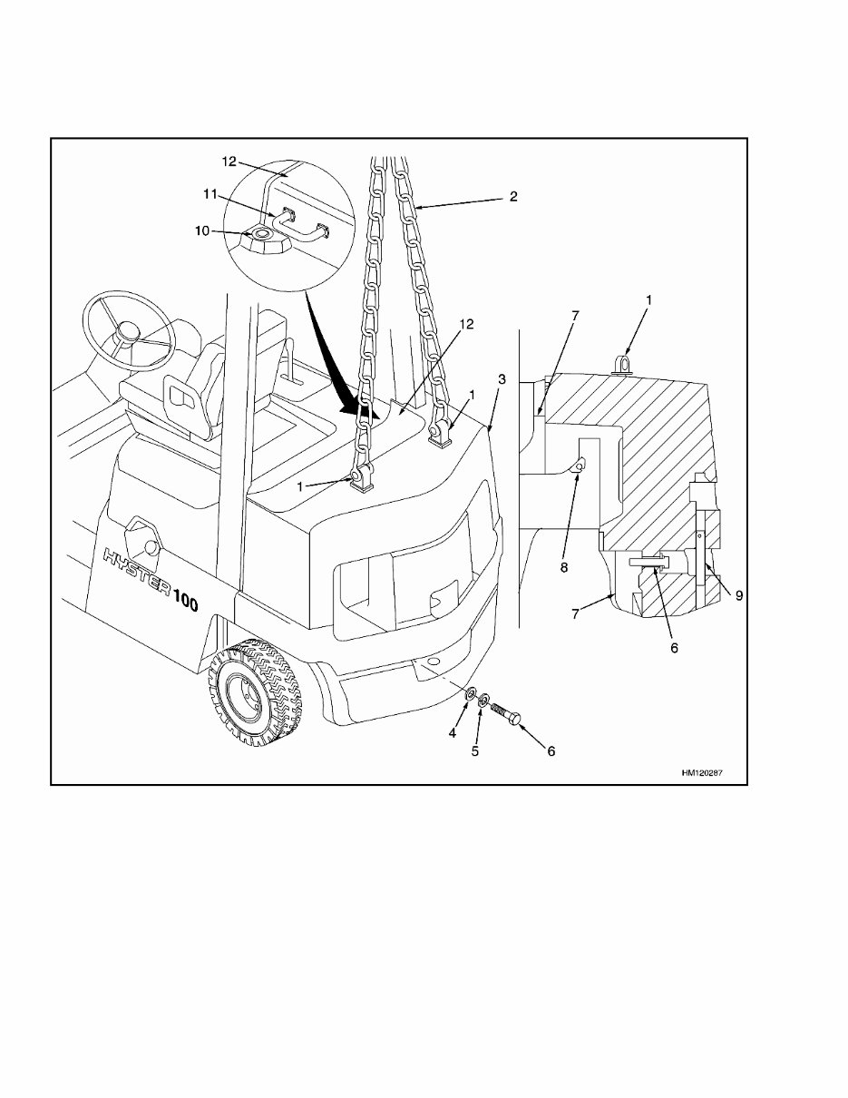
100 SRM 981 Counterweight Repair REMOVE WARNING The lift truck must be put on blocks for some types of maintenance and repair. The removal of the following assemblies will cause large changes in the center of gravity: mast, drive axle, engine and transmission, and the coun- terweight. When the lift truck is put on blocks, put additional blocks in the following posi- tions to maintain stability: • Before removing the mast and drive axle, put blocks under the counterweight so the lift truck cannot fall backward. • Before removing the counterweight, put blocks under the mast assembly so the lift truck cannot fall forward. The surface must be solid, even, and level when the lift truck is put on blocks. Make sure that any blocks used to support the lift truck are solid, one-piece units. See the Operating Manual or the Periodic Maintenance section for your lift truck. WARNING Do not operate the lift truck if the capscrew for the counterweight is not installed. When the capscrew is removed, the counterweight can fall from the lift truck. The counterweight is held in position on the frame by two hooks that are part of the frame. One large mounting capscrew holds the counterweight to the lower part of the frame. See Figure 2. If lift truck is equipped with an LPG fuel system, the LPG tank and tank mounting bracket must be removed before removing the counterweight. WARNING LPG can cause an explosion. Do not cause sparks or permit flammable material near the LPG system. LPG fuel systems can be discon- nected indoors only if the lift truck is at least 8 m (26 ft) from any open flame, motor vehicles, electrical source, or ignition source. NOTE: The LPG tank can be mounted on either a fixed mounting bracket or an EZ lift mounting bracket. If the tank is mounted on an EZ lift mount- ing bracket, follow Step 1 through Step 4 and Step 6 through Step 10. If a fixed mounting bracket is used, complete Step 1 through Step 3 and Step 5 through Step 10. If lift truck is equipped with either a diesel or gas fuel system, start at Step 6. 1. Move lift truck to an area where tanks are changed. 2. Close fuel shutoff valve on LPG tank, by turning valve clockwise. See Figure 3. Before any part of the LPG fuel system is disconnected, run engine until fuel in the system is used and engine stops. Turn key switch to OFF position. WARNING LPG is very cold in the atmosphere. Always wear gloves to protect your hands from the cold fittings. Do not permit LPG to contact the skin. 3. If engine will not run, close fuel shutoff valve on LPG tank. Loosen fitting on supply hose from LPG tank where it enters filter unit. Permit pressure in the fuel system to decrease slowly. Use a cloth or gloves to protect your hands from cold fitting. 4. Perform this step to remove LPG tank with an EZ lift mounting bracket from counterweight. WARNING LPG is very cold in the atmosphere. Always wear gloves to protect your hands from the cold fittings. Do not permit LPG to contact the skin. a. Disconnect quick-disconnect fitting. b. Grab tank handle on mounting bracket and swing tank out to left side of truck. See Fig- ure 4. c. Tilt mounting bracket to position tank verti- cally. d. Release tank strap and lift tank from mount- ing bracket. 3
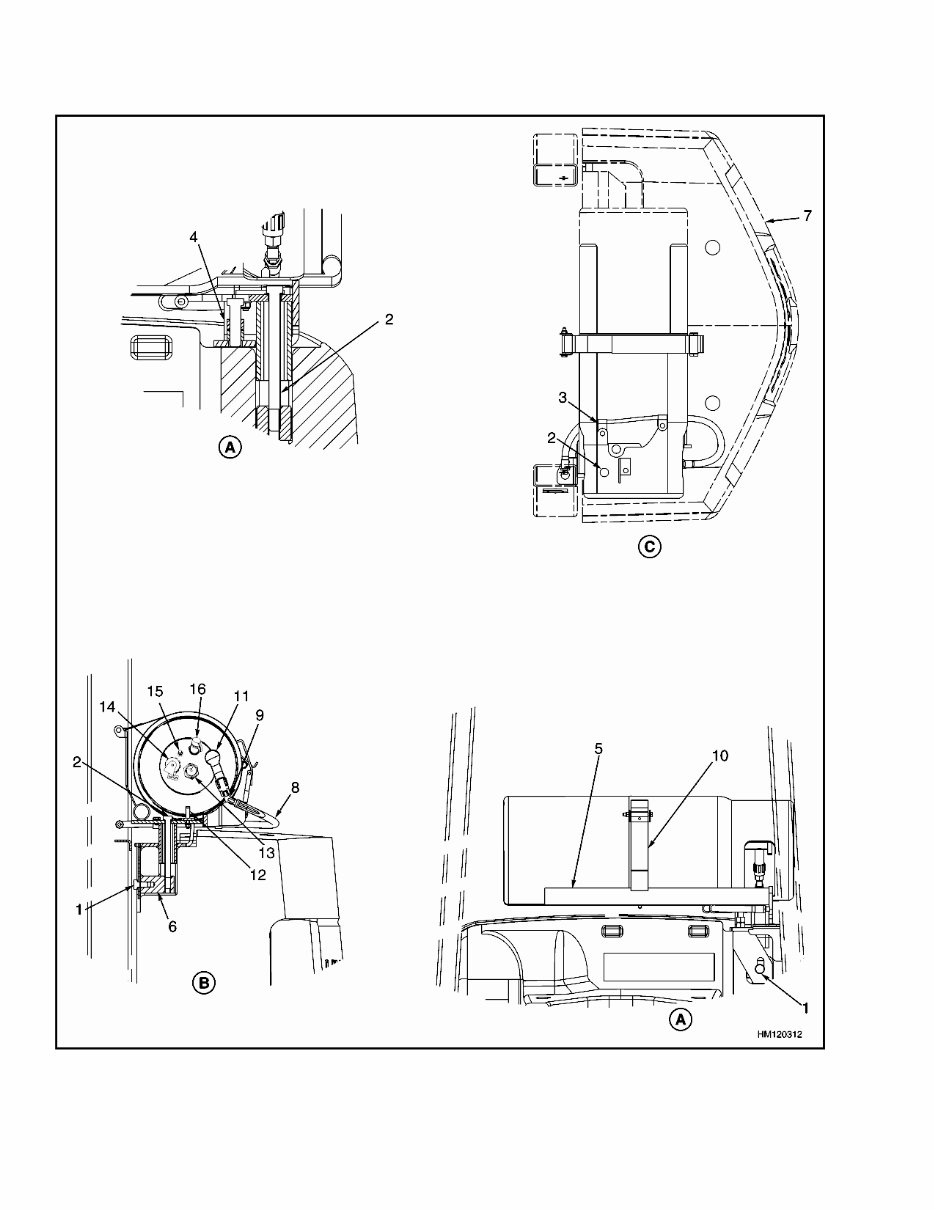
Counterweight Repair 100 SRM 981 Figure 3. Remove EZ Lift Mounting Bracket From Lift Truck 4 V/////777/A HM120313
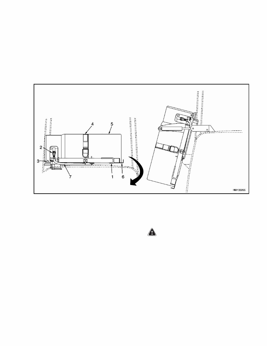
100 SRM 981 Counterweight Repair Legend for Figure 3 NOTE: SOME LPG TANKS HAVE A PLUG INSTEAD OF AN AUXILIARY FILL FITTING FOR ITEM (12). A. FRONT VIEW B. SIDE VIEW C. TOP VIEW 1. CAPSCREW 2. CAPSCREW 3. HOSE CLAMP 4. CAPSCREW 5. BRACKET ASSEMBLY 6. FASTENER BLOCK 7. COUNTERWEIGHT 8. SHUTOFF VALVE 9. QUICK-DISCONNECT FITTING 10. ALIGNMENT PIN 11. FUEL GAUGE 12. AUXILIARY FILL FITTING 13. LIQUID LEVEL INDICATOR 14. TANK RELIEF VALVE 1. TANK HANDLE 2. QUICK-DISCONNECT FITTING 3. ALIGNMENT PIN 4. TANK STRAP 5. LPG TANK 6. EZ LIFT MOUNTING BRACKET 7. LPG FUEL LINE Figure 4. Remove LPG Tank From EZ Lift Mounting Bracket e. Remove capscrew, located behind seat, from counterweight. Remove fastener block. See Figure 3. f. Remove capscrews from top of mounting bracket. g. Remove hose clamps. h. Remove mounting bracket assembly. 5. Perform this step if LPG tank is mounted on counterweight with a fixed mounting bracket. WARNING LPG is very cold in the atmosphere. Always wear gloves to protect your hands from the cold fittings. Do not permit LPG to contact the skin. a. Disconnect quick-disconnect fitting. See Fig- ure 5. b. Release tank strap and remove tank from bracket. c. Remove capscrew, located behind seat, from counterweight. Remove fastener block. See Figure 5. 5 HM130205
This is the complete factory service repair manual for the Hyster F004 (S80XM BCS) Forklift. It contains easy-to-read text sections with high-quality diagrams and instructions, suitable for both do-it-yourselfers and experienced mechanics. The manual provides step-by-step instructions, detailed exploded pictures, and diagrams to guide you through the correct and efficient completion of any required job.
The manual covers a wide range of topics including alternator with regulator, brake system, cooling system, drive axle, electronic control module (ECM) diagnostic troubleshooting, hydraulic system, periodic maintenance, and much more. It also includes information on servicing, maintenance, and troubleshooting for all models/engines/trim/transmission types of the Hyster F004 (S80XM BCS) Forklift.
It is an inexpensive way to ensure your vehicle is working properly and is the same manual used in local service/repair shops. The manual is guaranteed to be fully functional without any missing or corrupt parts or pages.
File Format: PDF
Language: English
Printable: Yes
Delivery: A download link will appear on the checkout page after payment is complete. There are no shipping fees, and you can start your repairs immediately.
Requirements: Adobe Reader
Buyers can pay for products via PayPal or Credit Card. Click on the instant payment button to pay with your PayPal or credit card and receive the download link instantly.
Whether you are a professional mechanic or a DIY enthusiast, this Hyster F004 (S80XM BCS) Forklift Service Repair Manual is an essential resource for maintaining and repairing your vehicle.
Recently Viewed
5,521,897Happy Clients
2,594,462eManuals
1,120,453Trusted Sellers
15Years in Business
Price:
Actual Price:
Hyster F004 (S80XM BCS) Forklift Service Repair Manual

 Forklift Service Repair Manual")