Table of Contents AC Motor Controllers/Display Panel TABLE OF CONTENTS (Continued) Key-On Initialization..................................................................................................................................... 50 Standard Display ........................................................................................................................................... 51 Premium Display ........................................................................................................................................... 51 Lift Truck Inspection Function ..................................................................................................................... 52 Access to Service Functions .......................................................................................................................... 52 Service Functions .......................................................................................................................................... 52 Service Functions .......................................................................................................................................... 53 Performance Modes ....................................................................................................................................... 55 Battery Discharge Indicator (BDI) ............................................................................................................... 55 Hourmeter ...................................................................................................................................................... 56 Dash Display Service Menu Navigation ........................................................................................................... 64 General ........................................................................................................................................................... 64 Moving Through Menu Selections ................................................................................................................ 64 Editing and Adding Information .................................................................................................................. 64 This section is for the following models: J2.00-3.20XM (J40-65Z) [A416/B416]; V30ZMD [D210/E210]; E1.50-2.00XM (E25-35Z, E40ZS) [E114/F114]; E2.00-3.20XM (E45-65Z) [G108]; E3.50-5.50XL, E4.50XLS (E70-120Z, E100ZS) [D098/E098] ii
2200 SRM 1056 Description Description GENERAL The alternating current (AC) system consists of AC motors, motor controller(s), a master controller, and a dash display. The major difference between the AC system and the direct current (DC) system is the master controller performs many of the same func- tions that previously were performed in the motor controllers on the DC system. AC Motors The AC motors are three-phase AC induction motors. They do not include motor brushes or commutators. An AC induction motor operates on three-phase AC power provided directly by the motor controller. The motor’s speed is controlled by the motor controller and can be changed by changing the frequency of the AC power provided to the motor. A speed sensor is built into the rear motor bearing, which provides RPM and direction feedback to the motor controller. The motor controller continuously monitors motor di- rection and speed. Using this feedback, the AC mo- tor control system can provide much better vehicle top speed control than is available with DC SEM sys- tems. The AC motors also have thermal sensors embedded in the motor windings that are continuously moni- tored by the motor controllers. Motor Controllers The motor controllers receive power from the truck’s battery and convert it into three-phase AC power at the frequencies and currents necessary to drive the respective pump and/or traction motor. Each AC in- duction motor provides feedback of speed, rotation direction, and temperature directly to the motor con- troller. The two motor controllers used to power the traction motor and hydraulic pump motor are very similar. The primary motor controller difference is in the power output rating. The motor controller logic board receives power from the key switch. Power to the motors can be inter- rupted indirectly by the key switch. The motor con- trollers get motor speed and temperature informa- tion directly from the motors. The motor controllers do not get any other input from the truck. The mas- ter controller relays speed, acceleration, and direc- tion commands to the motor controllers. Master Controller The master controller is a general-purpose mi- cro-controller for CANbus-based electric vehicles. It contains processing power, memory resources, analog and digital input/output (I/O) to provide the required full-featured functionality. The master controller is designed to manage the traction motor controller and pump motor controller, interface to the operator controls, auxiliary functions, and to control the vehicle dash display. The master controller also manages the operating truck parameters, status codes, battery discharge indicator (BDI) function, hourmeters, password fea- ture, and all operator inputs. It also controls the contactor, cooling fans, and strobe light relay. Dash Display The new AC dash display is similar in appearance to the SEM dash display and includes the same fea- tures. In addition, the AC dash display provides ex- panded service capabilities. The dash display has a password-accessible service mode that allows a tech- nician to change control settings and view real-time RPMs, current, temperature, and switch closure in- formation. Previously, a separate handset or com- puter was required for these operations. For a com- plete description of the display panel, see the Display Panel section of this manual. 1
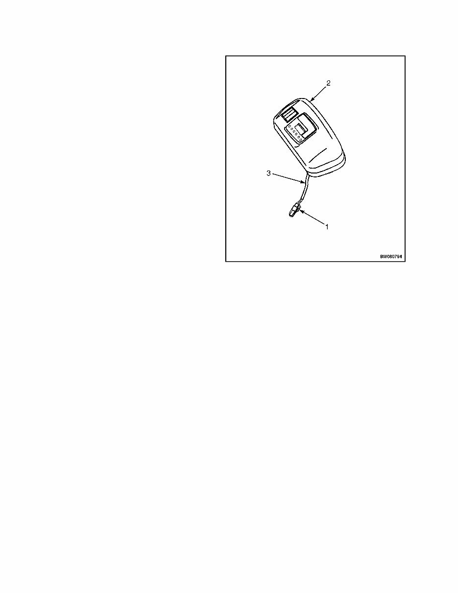
Master Controller Checks and Adjustments 2200 SRM 1056 Controller Area Network Bus (CANbus) The motor controllers, master controller, and dash display are connected together with a CANbus communication system. A personal computer (PC) with the appropriate Electric Truck AC Controller (ETACC) service software and interface cable can easily communicate with all system nodes by simply connecting to the CANbus. A diagnostics connector, located under the dash and next to the display, is configured specifically for this purpose. See Figure 1 and section Troubleshooting and Adjustments Using the AC Controls Program (ETACC) 2200 SRM 1058 for procedures to connect a PC to lift truck. 1. DIAGNOSTIC CONNECTOR 2. DASH DISPLAY 3. DASH WIRE HARNESS Figure 1. Diagnostic Connector Master Controller Checks and Adjustments NOTE: All checks and adjustments to the master controller can be done with a personal computer (PC) that has the ETACC service software installed. See Troubleshooting and Adjustments Using the AC Controls Program (ETACC) 2200 SRM 1058 for software installation procedures. A diagnostics connector in the wiring harness below the display panel can connect the PC to the CANbus system to communicate to the master controller (see Figure 1). Many checks can also be done at the display panel without being connected to a PC. The following checks and adjustments may be made using a PC or the dash display: • Check the system status codes history. • Check the state of charge of the battery. • Check the hourmeter readings on the traction cir- cuit and hydraulic pump controllers. • Monitor or adjust the register values for each func- tion as shown in Table 1, Table 2, and Table 3. 2
You're Reading a Preview
What's Included?
Lifetime Access
Fast Download Speeds
Offline Viewing
Access Contents & Bookmarks
Full Search Facility
Print one or all pages of your manual
$46.99
Hyster E114 (E1.50XM, E1.75XM, E2.00XM, E2.00XMS Europe) Service Shop Manual Forklift Workshop Repair Book
The Hyster E114 (E1.50XM, E1.75XM, E2.00XM, E2.00XMS Europe) Shop Repair Manual is a comprehensive resource for servicing, repairing, and maintaining your Hyster Fork Lift. It provides detailed instructions, step-by-step information, and troubleshooting procedures suitable for both professional mechanics and DIY enthusiasts.
This service manual covers a wide range of topics including the frame, cooling system, LPG fuel system, transmission, differential, steering and brake systems, hydraulic system, electrical components, instrument panel indicators, and more. It also includes diagrams, periodic maintenance guidelines, and specifications.
With easy navigation and detailed illustrations, exploded diagrams, and photos, this manual guides you through every service repair procedure efficiently. The manual is available in a printable PDF format, comprising 606 pages and is presented in English.
Whether you are looking to better understand, care for, or service your Hyster Fork Lift, this manual is an indispensable source of detailed maintenance and repair information. By utilizing this manual, you can effectively lower the repair and maintenance costs for your Hyster Fork Lift.
For those interested in purchasing this manual, it is instantly accessible and fully printable, allowing you to access the information whenever needed. Additionally, a wide selection of Hyster Service Manuals & Parts Catalogs are available to cater to specific models.
Hand pallet truck
Walkie low lift truck (powered pallet truck, usually electrically powered)
Rider low lift truck
Towing tractor
Walkie stacker
Rider stacker
Reach truck (small forklift, designed for small aisles, usually electrically powered, so-named because the forks can extend to reach the load)
Electric counterbalanced truck
IC counterbalanced truck
Sideloader
Telescopic handler
Walkie Order Picking truck
Rider Order Picking truck (commonly called an "Order Picker"; like a small forklift, except the operator rides up to the load and transfers it article by article)
Articulated Very Narrow Aisle Counterbalanced trucks (commonly called "Flexi or Bendi Truck")
Guided Very Narrow Aisle truck - 'Man Down' (a type of reach truck designed for aisles less than five feet wide) and 'Man Riser' Combination pickcle Picker/ Stacker truck
Truck Mounted Forklift / Sod Loader
These manuals are essential for understanding the various components and systems of forklifts, making them valuable resources for anyone involved in the repair and maintenance of these industrial trucks.
Reviews
Q&A
Recently Viewed
5,521,897Happy Clients
2,594,462eManuals
1,120,453Trusted Sellers
15Years in Business
Price:
Actual Price:
Hyster E114 (E1.50XM, E1.75XM, E2.00XM, E2.00XMS Europe) Service Shop Manual Forklift Workshop Repair Book





 Lifetime Access




