
 Forklift Service Manual")
Hyster E010 (S30FT) Forklift Service Manual
What's Included?
Fast Download Speeds
Offline Viewing
Access Contents & Bookmarks
Full Search Facility
Print one or all pages of your manual
STEERING AXLE
S30FT, S35FT, S40FTS [E010]; H1.6FT, H1.8FT, H2.0FTS
(H30FT, H35FT, H40FTS) [F001]; S2.0-3.5FT (S40-70FT, S55FTS
) [F187]; H2.0-3.5FT (H40-70FT) [L177]; S4.0, 4.5, 5.5FT, S5.5FTS (S80,
100, 120FT; S80, 100FTBCS; S120FTS; S120FTPRS) [G004];
H4.0FT5/FT6; H4.5FTS5, H4.5FT6; H5.0-5.5FT (H80, 90, 100, 110,
120FT) [N005, P005]; S6.0FT, S7.0FT, (S135FT, S155FT) [D024,
E024]; H6.0FT, H7.0FT (H135FT, H155FT) [H006, J006]
PART NO. 1580512 1600 SRM 1133

Steering Axle Table of Contents
TABLE OF CONTENTS
General ............................................................................................................................................................... 1
Steering Axle Assembly Repair ......................................................................................................................... 2
Remove ........................................................................................................................................................... 2
Disassemble ................................................................................................................................................... 3
Clean .............................................................................................................................................................. 3
Inspect ............................................................................................................................................................ 3
Assemble ........................................................................................................................................................ 10
Install ............................................................................................................................................................. 15
Spindles, Bearings, and Tie Rods Repair ......................................................................................................... 16
Spindles and Bearings ................................................................................................................................... 16
S2.0-3.5FT (S40-70FT, S55FTS) (F187), S4.0, 4.5, 5.5FT, S5.5FTS, (S80, 100, 120FT; S80,
100FTBCS; S120FTS; S120FTPRS) (G004), H4.0FT5/FT6; H4.5FTS5, H4.5FT6; H5.0-5.5FT
(H80, 90, 100, 110, 120FT) (N005, P005), S6.0FT, S7.0FT, (S135FT,S155FT) (D024, E024), and
H6.0FT, H7.0FT (H135FT, H155FT) (H006, J006).................................................................................. 16
Remove .................................................................................................................................................. 16
Disassemble ........................................................................................................................................... 17
Clean ...................................................................................................................................................... 18
Inspect ................................................................................................................................................... 18
Assemble ................................................................................................................................................ 18
Install..................................................................................................................................................... 19
Spindles and Bearings ................................................................................................................................... 22
S30FT, S35FT, S40FTS (E010), H1.6FT, H1.8FT, H2.0FTS (H30FT, H35FT, H40FTS) (F001),
and H2.0-3.5FT (H40-70FT) (L177) ......................................................................................................... 22
Remove and Disassemble ..................................................................................................................... 22
Assemble and Install ............................................................................................................................ 22
Tie Rods .......................................................................................................................................................... 23
S2.0-3.5FT (S40-70FT, S55FTS) (F187), and S4.0, 4.5, 5.5FT, S5.5FTS, (S80, 100, 120FT; S80,
100FTBCS; S120FTS; S120FTPRS) (G004)............................................................................................. 23
Remove .................................................................................................................................................. 23
Install..................................................................................................................................................... 24
Tie Rods .......................................................................................................................................................... 25
S30FT, S35FT, S40FTS (E010), H1.6FT, H1.8FT, H2.0FTS (H30FT, H35FT, H40FTS) (F001),
H2.0-3.5FT (H40-70FT) (L177), H4.0FT5/FT6; H4.5FTS5, H4.5FT6; H5.0-5.5FT (H80, 90,
100, 110, 120FT) (N005, P005), S6.0FT, S7.0FT, (S135FT,S155FT) (D024, E024) and H6.0FT,
H7.0FT (H135FT, H155FT) (H006, J006) ................................................................................................ 25
Remove .................................................................................................................................................. 25
Install..................................................................................................................................................... 25
Steering Cylinder Repair ................................................................................................................................... 28
Remove and Disassemble .............................................................................................................................. 28
Clean and Inspect .......................................................................................................................................... 29
Assemble and Install ..................................................................................................................................... 29
Torque Specifications ......................................................................................................................................... 30
©2008 HYSTER COMPANY i

Table of Contents Steering Axle
TABLE OF CONTENTS (Continued)
This section is for the following models:
S30FT, S35FT, S40FTS [E010];
H1.6FT, H1.8FT, H2.0FTS (H30FT, H35FT, H40FTS) [F001];
S2.0-3.5FT (S40-70FT, S55FTS ) [F187];
H2.0-3.5FT (H40-70FT) [L177];
S4.0, 4.5, 5.5FT, S5.5FTS (S80, 100, 120FT; S80, 100FTBCS;
S120FTS; S120FTPRS) [G004];
H4.0FT5/FT6; H4.5FTS5, H4.5FT6; H5.0-5.5FT (H80, 90, 100,
110, 120FT) [N005, P005];
S6.0FT, S7.0FT, (S135FT, S155FT) [D024, E024];
H6.0FT, H7.0FT (H135FT, H155FT) [H006, J006]
ii
1600 SRM 1133 General
General
This section has the description and repair proce-
dures for the steering axle.
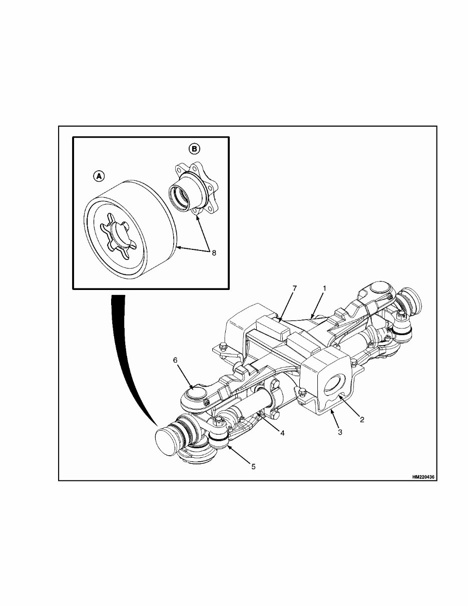
The steering axle assembly includes an axle
frame, steering cylinder, and two spindle and
hub assemblies. See Figure 1. The steering axle is
articulated and is connected to the frame by center
pivot mounts. The center pivot mounts permit the
steering axle to move in the frame mount when the
lift truck travels over rough surfaces.
A. CUSHION TRUCKS ONLY B. PNEUMATIC TRUCKS ONLY
1. AXLE FRAME
2. MOUNT
3. BRACKET
4. STEERING CYLINDER
5. TIE ROD
6. SPINDLE
7. MOUNT
8. HUB ASSEMBLIES
Figure 1. Steering Axle
1

Steering Axle Assembly Repair 1600 SRM 1133
The end caps of the steering cylinder are also the
mounts for the cylinder and are held to the shell by
the mount capscrews. There are O-rings, seals, and
wipers in the end caps to seal the caps to the shell
and rod. The ends of the piston rod extend from both
ends of the cylinder. A single piston and the seal are
at the center of the rod. Oil pressure on one side of
the piston moves the piston in the bore. The piston
pushes an equal amount of oil from the opposite side
of the cylinder.
When the piston reaches the end of the stroke, a re-
lief valve in the steering circuit controls the oil pres-
sure. The tie rods that connect the spindle arms to
the cylinder are not adjustable.
Each spindle turns on two tapered roller bearings in
mounts in the axle frame. The preload on the bear-
ings is controlled by shims at the lower bearing cap.
The wheels rotate on two tapered roller bearings and
are held on the spindles by a castle nut. The bearing
preload of the wheels is adjusted by the castle nut.
The grease seals protect the bearings from dirt and
water. Wear sleeves protect the hub from wear by the
seals.
Steering Axle Assembly Repair
REMOVE
WARNING
PUTTING THE LIFT TRUCK ON BLOCKS
The lift truck must be put on blocks for some
types of maintenance and repair. The removal
of the mast, drive axle, battery, or counter-
weight assemblies will cause large changes
in the center of gravity. When the lift truck
is put on blocks, put additional blocks in the
following positions:
• If the mast and drive axle are removed, put
blocks under the counterweight so the lift
truck cannot fall backward.
• If the counterweight is removed, put blocks
under the mast so that the lift truck cannot
fall forward.
Put the lift truck on blocks on a solid, even, and
level surface. Verify the blocks or stands have
enough capacity to hold the lift truck. Use ad-
ditional blocks next to the tires as necessary to
prevent movement of the lift truck. Verify the
lifting devices used during repairs can lift the
weight of the parts and assemblies.
See the Operating Manual or Periodic Mainte-
nance section for your lift truck model, for the
procedures to put the lift truck on blocks.
The steering axle can be removed without removing
the counterweight.
1. Verify wheels are set for straight travel. Put lift
truck on blocks so the steering axle will have
enough clearance to be removed. The top of the
axle frame must have clearance under the bot-
tom of the frame at the rear of the lift truck.
2. Disconnect hydraulic lines at steering cylinder.
Install plug fittings in cylinder and put caps on
hydraulic lines. Plug fittings will prevent spin-
dles from turning as axle is removed from under
the lift truck.
NOTE: Steering Axle Assembly may be mounted to
the frame with brackets or plates.
3. Slide floor jack or forks of another lift truck under
steering axle. Raise lifting device until it holds
the weight of the axle assembly.
a. To remove bracket type mounts, remove four
capscrews and nuts that fasten two brackets
under rubber mounts. For lift truck mod-
els S2.0-3.5FT (S40-70FT, S55FTS) (F187),
see Figure 2, for lift truck modelsH2.0-3.5FT
(H40-70FT) (L177), see Figure 3, for lift truck
models S4.0, 4.5, 5.5FT, S5.5FTS, (S80, 100,
120FT; S80, 100FTBCS; S120FTS; S120FT-
PRS) (G004), see Figure 5, and for H4.0FT5/
FT6; H4.5FTS5, H4.5FT6; H5.0-5.5FT (H80,
90, 100, 110, 120FT) (N005, P005), see Fig-
ure 6. Remove brackets and slowly lower
axle assembly onto wheels. Carefully roll
steering axle assembly away from lift truck.
2
You're Reading a Preview
What's Included?
Fast Download Speeds
Offline Viewing
Access Contents & Bookmarks
Full Search Facility
Print one or all pages of your manual
$41.99
$54.99
Viewed 42 Times Today


Secure transaction
What's Included?
Fast Download Speeds
Offline Viewing
Access Contents & Bookmarks
Full Search Facility
Print one or all pages of your manual
$41.99
$54.99
This manual provides comprehensive maintenance and repair procedures for the Hyster E010 (S30FT) Forklift.
- Covers the following models:
- Hyster E010 (S30FT) Forklift Service Repair Factory Manual
Service Repair Factory Manual Covers:
- Brake System
- Calibration Procedures
- Capacities and Specifications
- Cooling System
- Cummins QSB 3.3L Fault Codes
- Cylinder Repair
- Diagnostic Trouble Codes
- Diagnostic Troubleshooting Manual
- Diagrams and Schematics
- Drive Axle and Differential Assembly Repair
- Electrical System
- Frame
- Gasoline Fuel System
- Hydraulic Gear Pump
- LPG Fuel System
- Main Control Valve
- Mast Repairs
- Mazda Engine
- Metric and Inch (SAE) Fasteners
- Operational Checkout
- Periodic Maintenance
- Powershift Transmission
- Steering Axle
- User Interface
- Wire Harness Repair
Hyster E010 (S30FT) Forklift Service Repair Factory Manual is written in a detailed step-by-step manner, making it easy for both professional mechanics and DIY enthusiasts to use for repair and maintenance, potentially saving on expenses.
File Format: .PDF
Compatible: All Versions of Windows & Mac
Language: English
Requirements: Adobe Reader


