SAFETY PRECAUTIONS MAINTENANCE AND REPAIR • When lifting parts or assemblies, make sure all slings, chains, or cables are correctly fastened, and that the load being lifted is balanced. Make sure the crane, cables, and chains have the capacity to support the weight of the load. • Do not lift heavy parts by hand, use a lifting mechanism. • Wear safety glasses. • DISCONNECT THE BATTERY CONNECTOR before doing any maintenance or repair on electric lift trucks. • Disconnect the battery ground cable on internal combustion lift trucks. • Always use correct blocks to prevent the unit from rolling or falling. See HOW TO PUT THE LIFT TRUCK ON BLOCKS in the Operating Manual or the Periodic Mainte- nance section. • Keep the unit clean and the working area clean and orderly. • Use the correct tools for the job. • Keep the tools clean and in good condition. • Always use HYSTER APPROVED parts when making repairs. Replacement parts must meet or exceed the specifications of the original equipment manufacturer. • Make sure all nuts, bolts, snap rings, and other fastening devices are removed before using force to remove parts. • Always fasten a DO NOT OPERATE tag to the controls of the unit when making repairs, or if the unit needs repairs. • Be sure to follow the WARNING and CAUTION notes in the instructions. • Gasoline, Liquid Petroleum Gas (LPG), Compressed Natural Gas (CNG), and Diesel fuel are flammable. Be sure to follow the necessary safety precautions when handling these fuels and when working on these fuel systems. • Batteries generate flammable gas when they are being charged. Keep fire and sparks away from the area. Make sure the area is well ventilated. NOTE: The following symbols and words indicate safety information in this manual: WARNING Indicates a condition that can cause immediate death or injury! CAUTION Indicates a condition that can cause property damage!
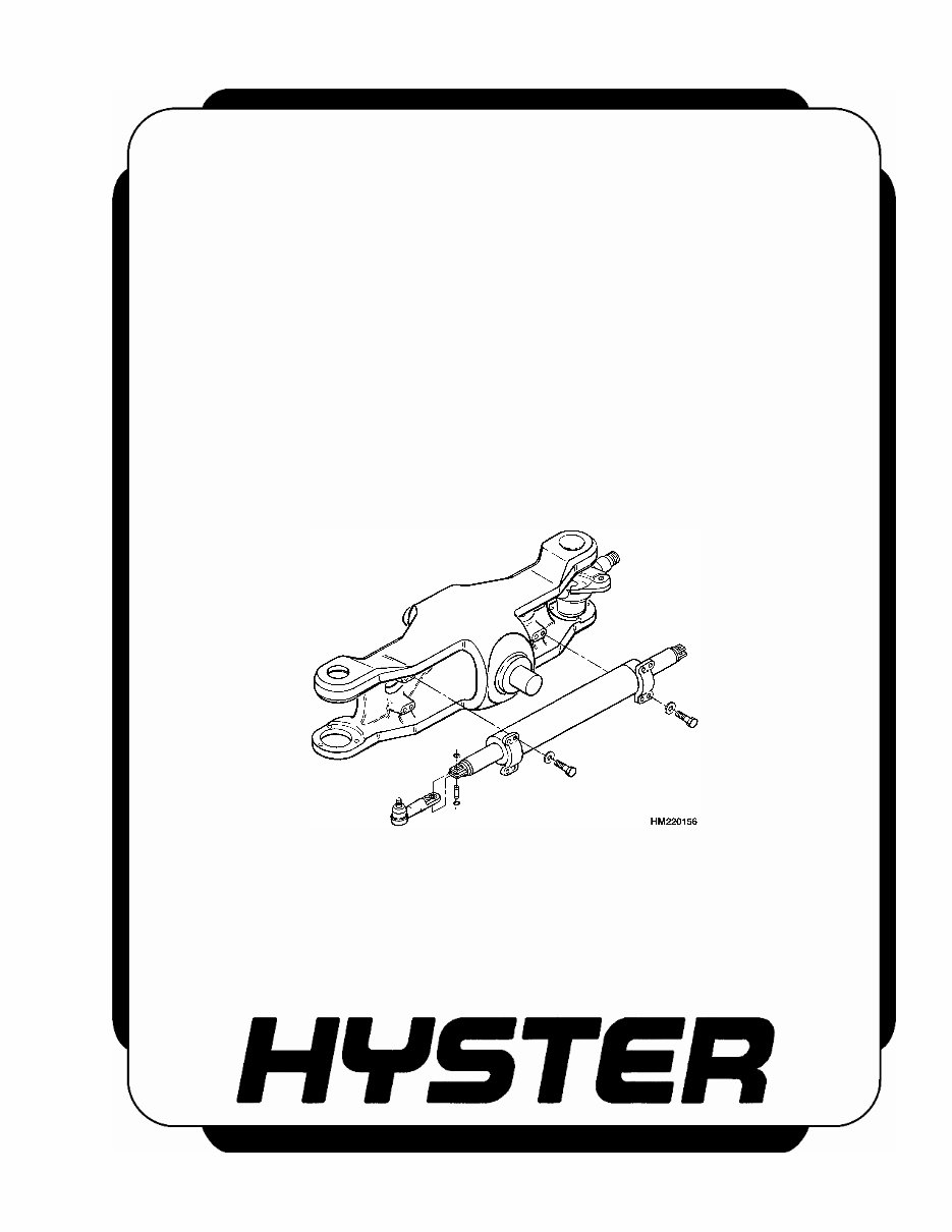
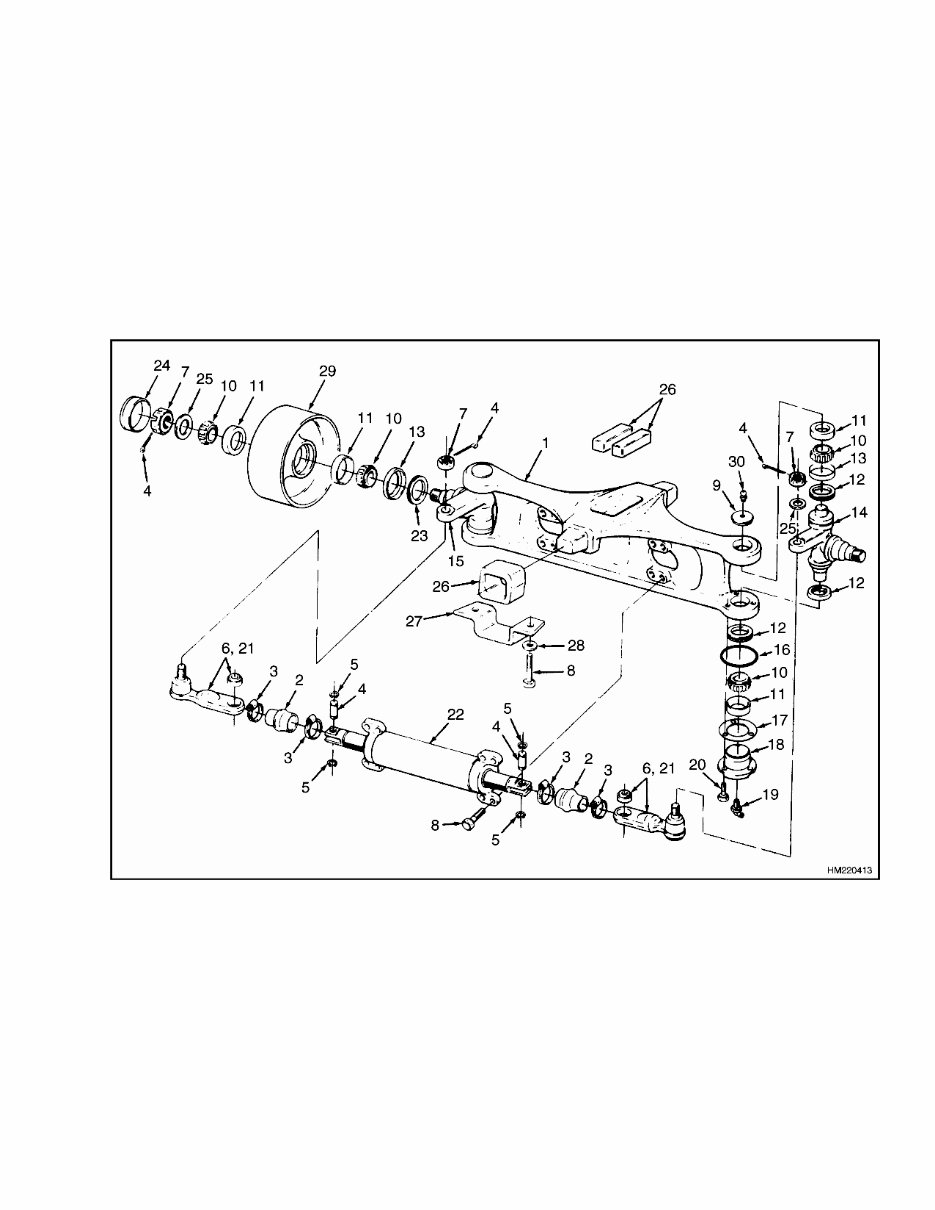
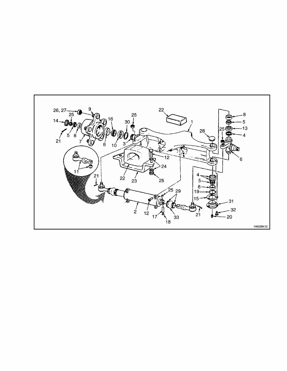
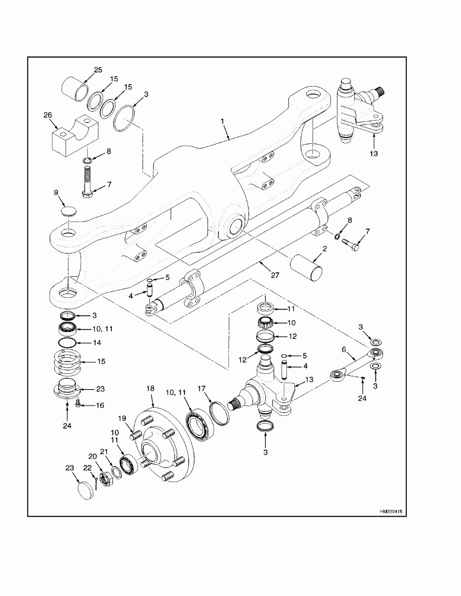
1600 SRM 326 Description General This section has the description and repair procedures for the steering axle. For information on the steering control unit, see the section Steering Control Unit. Description The steering axle assembly includes an axle frame, steering cylinder, tie rods, and two spindle and hub assemblies. The steering axle is articulated and is connected to the frame with center pivot mounts. The center pivot mounts permit the steering axle to move in the frame mount when the lift truck travels over rough surfaces. See Figure 1, Figure 2, Figure 3, and Figure 4. 1. STEERING AXLE 2. COVER 3. CLAMP 4. COTTER PIN 5. SNAP RING 6. TIE ROD AND BUSHING 7. NUT 8. CAPSCREW 9. CAP 10. BEARING CONE 11. BEARING CUP 12. SEAL 13. WEAR SLEEVE 14. SPINDLE (RH) 15. SPINDLE (LH) 16. O-RING 17. SHIM 18. BEARING CAP 19. LUBE FITTING 20. SCREW 21. SEALANT 22. STEER CYLINDER 23. OIL SEAL 24. CAP (HUB) 25. WASHER 26. MOUNT 27. PLATE 28. LOCKWASHER 29. WHEEL 30. GREASE FITTING Figure 1. Steering Axle E3.50-5.50XL (E70-120XL, E70-120XL 3 ) (C098), S3.50-5.50XL (S70-120XL) (D004), and S3.50-5.50XM (S70-120XM) (E004, F004) 1
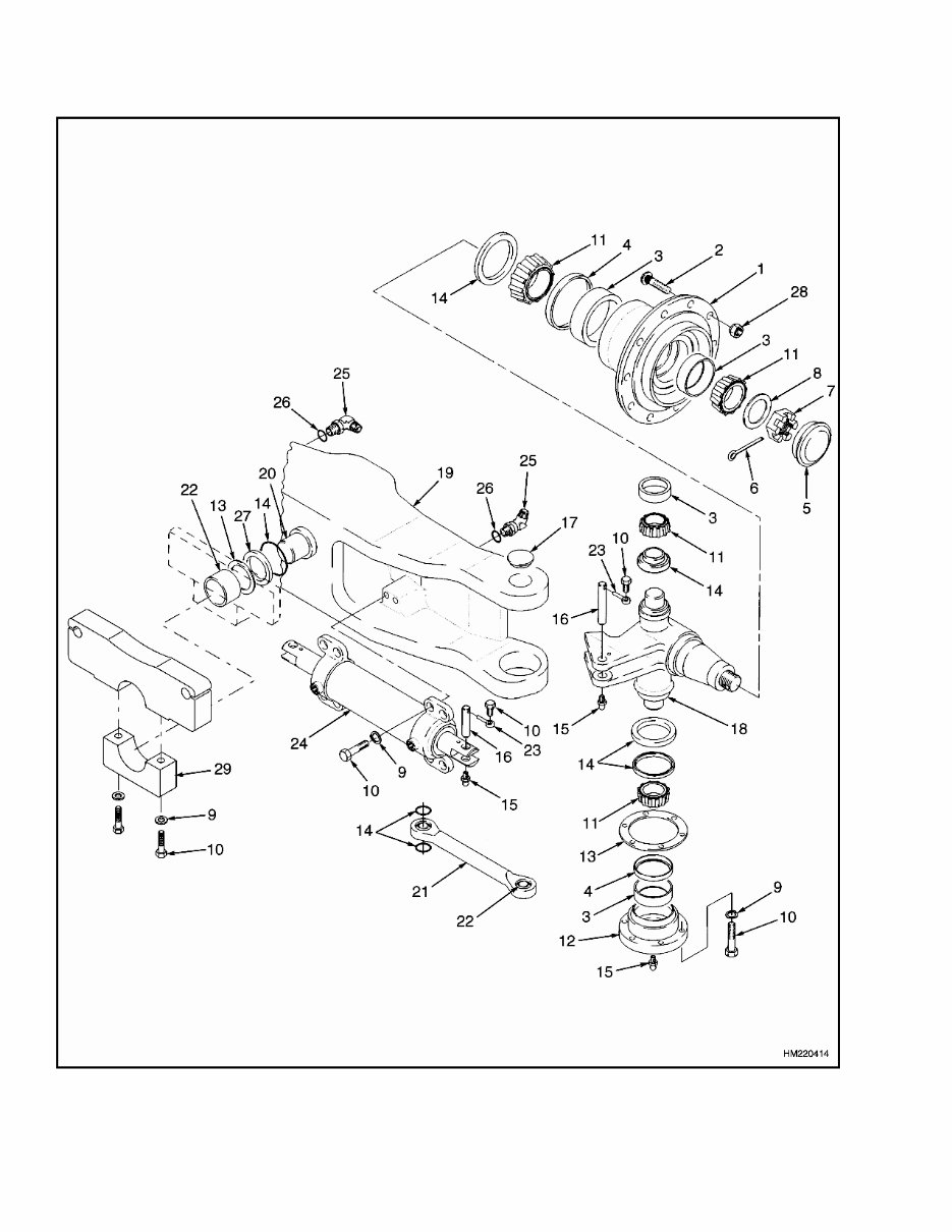
1600 SRM 326 Steering Axle Assembly Repair Legend for Figure 4 1. STEERING AXLE 2. SHAFT 3. SEAL 4. PIN 5. SNAP RING 6. TIE ROD 7. CAPSCREW 8. LOCKWASHER 9. PLUG 10. BEARING CONE 11. BEARING CUP 12. WEAR SLEEVE 13. SPINDLE 14. O-RING 15. SHIM 16. SCREW 17. OIL SEAL 18. HUB 19. STUD 20. WHEEL NUT 21. WASHER 22. COTTER PIN 23. CAP 24. GREASE FITTING 25. BUSHING 26. BEARING CAP 27. STEER CYLINDER The center pivots for the axle are installed in rubber mounts on the following units: H3.50-5.50XL (H70-110XL) (D004) S3.50-5.50XL (S70-120XL) (G005) S3.50-5.50XM (S70-120XM) (E004, F004) E3.50-5.50XL (E70-120XL, E70-120XL 3 ) (C098) The center pivots for the axle are installed in the frame of the lift truck and rotate in fiber bushings on the following units: H6.00-7.00XL (H135-155XL, H135-155XL 2 ) (F006, G006) H8.00-16.00XL (H165-360XL) (D019, E007) H8.00-16.00XM (H170-360HD) (E019, F007, F019, G007) The end caps of the steering cylinder are also the mounts for the cylinder and are held to the axle by capscrews. The ends of the piston rod extend from both ends of the cylinder. A single piston and the seal are at the center of the piston rod. Oil pressure on one side of the piston moves the piston in the bore. The piston pushes an equal amount of oil from the opposite side of the cylinder. The oil returns to the steering control unit. When the piston in the steering cylinder reaches the end of the stroke, a relief valve controls the oil pres- sure. The relief valve for the steering system is in the manifold block that is installed on the steering control unit. Each spindle turns on two tapered roller bearings in the axle frame. The preload on the bearings is con- trolled by shims at the lower bearing cap. The tie rods that connect the spindle arms to the cylinder do not have an adjustment. The wheel hubs rotate on two tapered roller bear- ings and are held on the spindles by a castle nut. The bearing preload of the wheel hubs is adjusted by the castle nut. The grease seals protect the bearings from dirt and water. Wear sleeves prevent the seals from causing wear on the hub. Steering Axle Assembly Repair STEERING AXLE H3.50-5.00XL (H70-110XL) (G005), S3.50-5.50XL (S70-120XL) (D004), S3.50-5.50XM (S70-120XM) (E004, F004), AND E3.50-5.50XL (E70-120XL, E70-120XL 3 ) (C098) Remove WARNING Put the lift truck on blocks. Follow the proce- dures for raising the lift truck described in the Operating Manual for this lift truck. The sur- face must be solid, even, and level. Make sure the blocks are solid, one-piece units. Make sure the lifting devices used during repairs can lift the weight of the parts. The steering axle can be removed without removing the counterweight. 1. Make sure wheels are set for straight travel. Put blocks under frame in front of steer wheels and under counterweight so steering axle can be re- moved. The top of the axle frame must have clearance under the counterweight so that the steering axle can be removed. 2. It is not required, but it can make removal of the axle easier if wheels are removed. See Wheels and Hubs Repair (All Units) for wheel removal. Disconnect hydraulic lines at steering cylinder. 5
Steering Axle Assembly Repair 1600 SRM 326 Install caps on cylinder and put plugs in hy- draulic lines. Caps will prevent spindles from turning when axle is removed from the lift truck. 3. Slide a floor jack or forks of another lift truck under steering axle. Raise lifting device until it holds the weight of the axle assembly. Remove four capscrews and nuts that fasten two brack- ets under rubber mounts. Remove brackets and slowly lower axle assembly. Carefully remove axle assembly from under lift truck. Install 1. Install rubber mounts on axle. Make sure part number is away from axle frame and tapered edge of rubber mount is at the top. See Fig- ure 1and Figure 3. 2. Apply a lubricant that is approved for use with rubber (tire lubricant) to the rubber mounts. Lubricant is used where rubber mount fits into frame brackets. 3. Use a floor jack or another lift truck to put steer- ing axle into position in the frame. Make sure rubber mounts fit inside frame brackets for the mounts. If necessary, lower weight of the lift truck onto axle to make sure rubber mounts fit completely in frame brackets. 4. Install bottom brackets for rubber mounts. H3.50-5.00XL (H70-110XL) (G005) units. Tighten four bolts for brackets to 72 N•m (53 lbf ft). S3.50-5.50XL (S70-120XL) (D004), S3.50- 5.50XM (S70-120XM) (E004, F004), and E3.50-5.50XL (E70-120XL, E70-120XL 3 ) (C098) units. Tighten four bolts to 110 N•m (81 lbf ft). 5. Remove plugs and caps and connect hydraulic lines to steering cylinder. Install wheels if they were removed. 6. Operate steering system to remove air from sys- tem. Turn steering wheel several times from one wheel stop to other wheel stop. Check for hy- draulic leaks. STEERING AXLE H6.00-7.00XL (H135-155XL, H135-155XL 2 ) (F006, G006), H8.00-16.00XL (H165-360XL) (D019, E007), AND H8.00-16.00XM (H170-360HD) (E019, F007, F019, G007) Remove WARNING Put the lift truck on blocks. Follow the proce- dures for raising the lift truck described in the Operating Manual for this lift truck. The sur- face must be solid, even, and level. Make sure the blocks are solid, one-piece units. Make sure the lifting devices used during repairs can lift the weight of the parts. The steering axle can be removed without removing the counterweight. 1. Make sure wheels are set for straight travel. Put blocks under frame in front of steer wheels, so steering axle can be removed. Top of axle frame must have clearance under counterweight so steering axle can be removed. 2. It is not required, but it can make removal of the axle easier if the wheels are removed. Dis- connect hydraulic lines at steering cylinder. In- stall caps on cylinder and put plugs in hydraulic lines. Caps will prevent spindles from turning when axle is removed from under the lift truck. 3. Remove two dust covers from openings of bearing caps. 4. Slide a floor jack or forks of another lift truck under steering axle. Raise lifting device until it holds weight of axle assembly. Remove four cap- screws and washers that fasten two bearing caps to frame. Remove bearing caps and slowly lower axle assembly. Carefully remove axle assembly from under lift truck. 6
The Service workshop repair manual provides detailed servicing instructions for your Hyster Fork Lift. It offers complete step-by-step information on repair, servicing, preventative maintenance, and troubleshooting procedures. This comprehensive manual features photos, illustrations, and detailed instructions to guide you through the entire repair process. It contains all the necessary information to keep your Hyster Fork Lift working correctly, making it an indispensable source of maintenance and repair information for both professional mechanics and DIY enthusiasts.
This manual covers the following:
h165-280xl (d007 / e007) h300-360xl (c019 / d019)
Frame
Perkins diesel engine-1000 series
GM V8-366 engine
Perkins diesel engine-1000 series (ar, yg, yh)
Cooling system
LPG fuel system
Three-speed ps trans - descr / oper
Three-speed ps trans - repair
Three-speed ps trans - descr / oper (hyster-t50)
Three-speed ps trans - repair (hyster-t50)
Autoshift transmission controller
Differential
Planetary gear axle
Steering axle
Steering system
Brake system
Air compressor
Tu-flo air compressor (GM V8-366 eng)
Hydraulic system
Main control valve
Tilt control valve
Tilt cylinders
Alternator
Starter
High energy ignition system
Instrument panel indicators and senders
Masts
Empty container handling attachment
Inch (SAE) and metric fasteners
Periodic maintenance
Capacities and specifications
Diagrams
Whether you are a professional mechanic or a DIY enthusiast, this manual will help you better understand, care for, and service your Hyster Fork Lift, ultimately lowering the repair and maintenance costs.