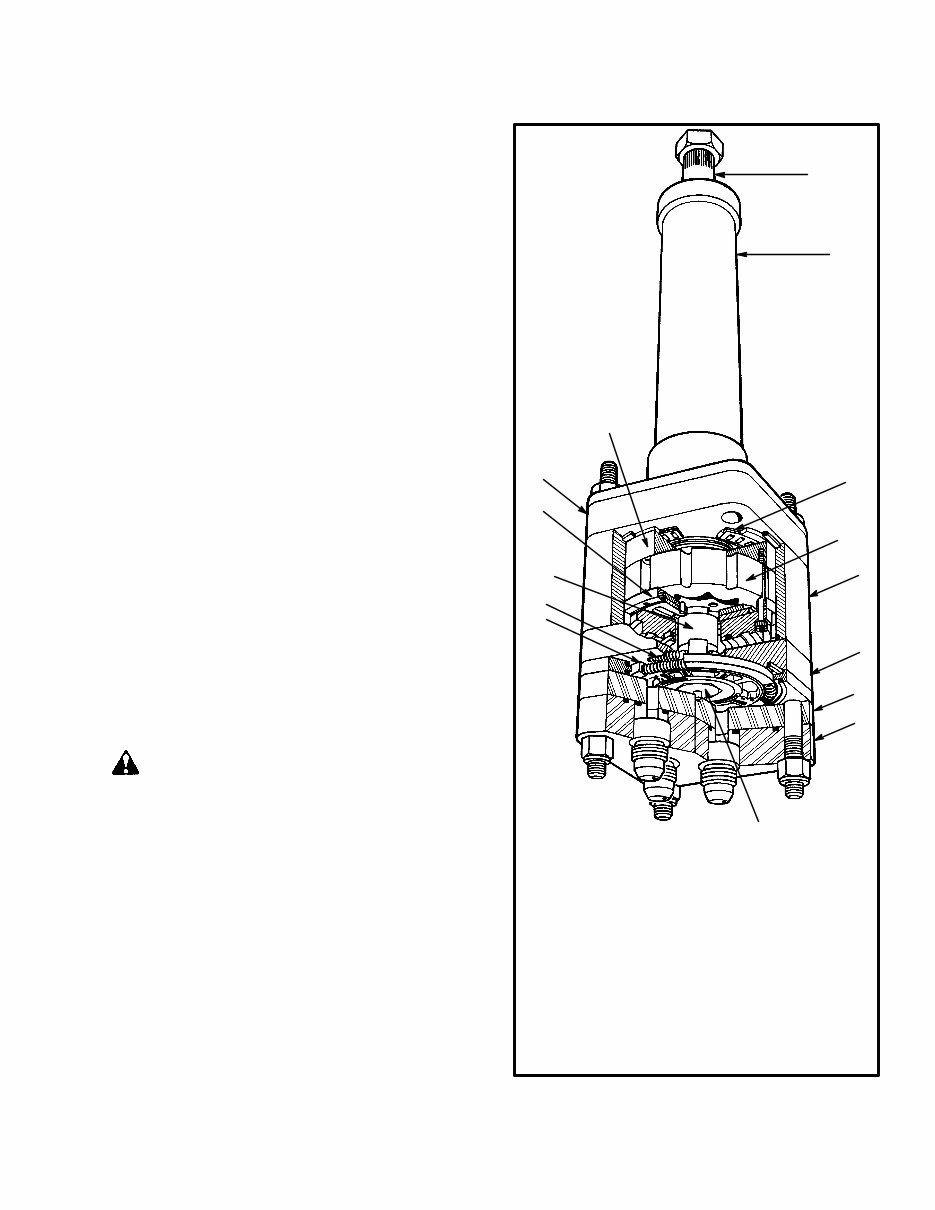
1 INTRODUCTION This section has the description and operation for the HGF Hydraguide steering control unit made by Ross Gear. The disassembly and assembly procedure is for making repairs. A Troubleshooting chart is at the end of the section. DESCRIPTION The steering control unit has two sections: a fluid con- trol valve and a fluid metering section. The two sections are connected hydraulically and mechanically inside of the housing. Control Valve Section The open center control valve is a rotating valve plate. The control valve controls the pressure and flow of the hydraulic oil to the steering cylinder. The valve plate is held in its center position by two sets of three coil springs. When the valve plate is in the center position, hydraulic oil flows from the hydraulic pump, through the steering control unit, and returns to the hydraulic tank. When the valve plate is moved from its center po- sition by the steering wheel, a port is opened in the isola- tor manifold and hydraulic pressure is sent to the meter- ing section. Metering Section WARNING The use of the steering control unit as a pump for manual steering can damage the unit if the torque on the steering wheel is greater than 170 N.m (125 lb f ft). This damage will cause the complete loss of control of the steering system. The metering section has the following three functions: • measures the hydraulic oil to the steering cylin- der • keeps a constant ratio of steering wheel turns to the direction of the steered wheels • operates as a pump for manual steering of the lift truck if hydraulic pressure is not available from the hydraulic pump FIGURE 1. ROSS HGF STEERING CONTROL UNIT 1. PORT COVER 2. PORT MANIFOLD 3. ISOLATOR MANIFOLD 4. METERING RING 5. ROTOR ASSEMBLY 6. UPPER COVER PLATE 7. DRIVE ASSEMBLY 8. VALVE SPRINGS 9. VALVE ASSEMBLY 10. DRIVE LINK 11. COMMUTATOR ASSEMBLY 12. DRIVE PLATE 13. THRUST BEARING 14. COVER AND TUBE ASSEMBLY 15. INPUT SHAFT FROM STEERING WHEEL 11124 15 14 13 12 11 10 9 8 7 6 5 4 3 2 1
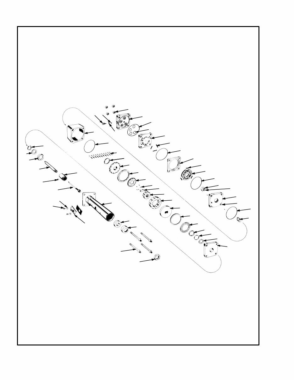
2 FIGURE 2. PARTS FOR THE STEERING CONTROL UNIT 11. ALIGNMENT PIN (9) 12. VALVE RING 13. VALVE PLATE 14. SPRING 13 mm (0.50 in) 15. ISOLATOR MANIFOLD 16. DRIVE LINK 17. METERING RING 18. CAPSCREW, SOCKET HEAD (11) 19. SEAL, COMMUTATOR 20. COMMUTATOR COVER 21. COMMUTATOR RING 22. COMMUTATOR 23. SPACER, LINK DRIVE 24. ROTATOR 25. STATOR 26. DRIVE PLATE 27. SPACER, THRUST BEARING 28. THRUST BEARING 29. FACE SEAL 30. BACK–UP RING 31. SEAL SPACER 32. UPPER COVER PLATE 33. INPUT SHAFT 34. RETAINER RING 35. WASHER, RETAINER PLATE 36. RETAINER PLATE 37. UPPER COVER AND JACKET TUBE 38. BUSHING 39. SEAL 40. SPECIAL BOLT 5 / 16 x 24 UNF–2A (4) 1. NUT 5 / 16 x 24 UNF (4) 2. PORT COVER 3. SEAL RING 4. O–RING (4) 5. BALL 6 mm ( 7 / 32 in) 6. PLUG 7. O–RING 8. PORT MANIFOLD 9. SPRING 19 mm (0.75 in) 10. DRIVE ASSEMBLY 41. NUT 42. SCREW 43. CONTACT RING ASSEMBLY 44. CONTACT BRUSH ASSEMBLY 45. SCREW AND LOCKWASHER 46. SPACER 47. HORN WIRE ASSEMBLY 1 2 3 4 5 6 7 8 9 10 12 13 14 15 16 17 18 19 20 21 22 23 24 25 26 27 28 29 30 31 32 33 34 35 36 37 38 39 40 41 42 43 44 45 46 47 3 3 11 11 3 3 11
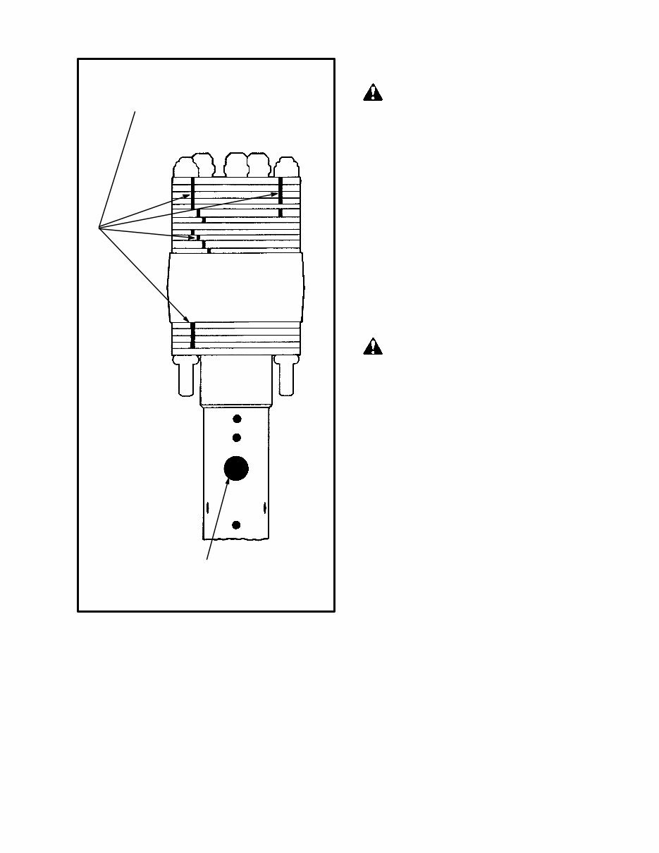
3 FIGURE 3. ILLUSTRATION FOR COMPONENT GROOVE ALIGNMENT Components with alignment grooves must be assembled as shown in the illustration. The alignment grooves make sure that the parts are in the correct position. Make a note of the contact brush assembly. The position of the hole from the alignment grooves must be the same when the steering control unit is assembled. The procedures and illustrations in this section are supplied by the Ross Gear Division of TRW. DISASSEMBLY AND INSPECTION WARNING Use a work area with good ventilation when solvents are used. Keep fire and sparks away from the area. Commercial cleaning solvents may be flammable and toxic, and can cause severe skin irritation. When using commercial cleaning solvents, always comply with the solvent manufacturer’s recommended safety precautions. Wear eye protection when making repairs described in this section. Compressed air can move particles so that they cause injury to the user or to other personnel. Make sure that the path of the compressed air is away from all personnel. Wear protective goggles or a face shield to prevent injury to the eyes. CAUTION Use a puller to remove the steering wheel from the in- put shaft. Do not use a hammer to remove the steer- ing wheel or the steering control unit can be dam- aged. Do not put the steering control unit directly into a vise. The clamp pressure will cause distortion and damage. Make a service assembly fixture as shown in FIGURE 4. Make sure you understand the procedures described in this section before you begin disassembly and repair. Keep a clean area for the parts and assemblies. The parts are machined to small tolerances. Use minimum force and carefully disassemble and assemble the parts. Do not permit damage to occur from small scratches, dam- age, and dirt. Use a petroleum solvent to clean the parts. Dry the parts with compressed air. Some parts are bonded together and must be replaced as a single part. Disassemble the parts only as described in this section. Some parts have a special small tolerance and can be only replaced as an assembly.
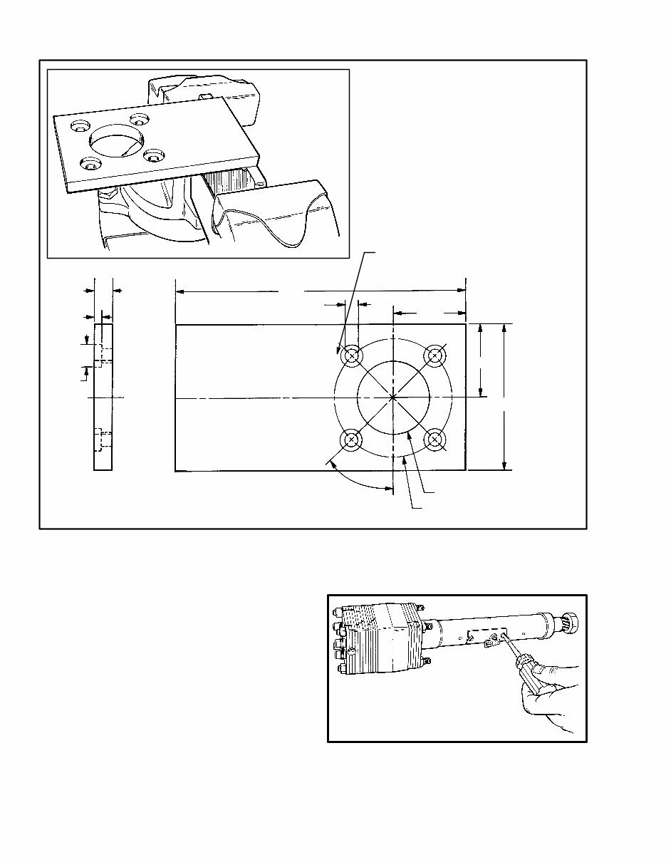
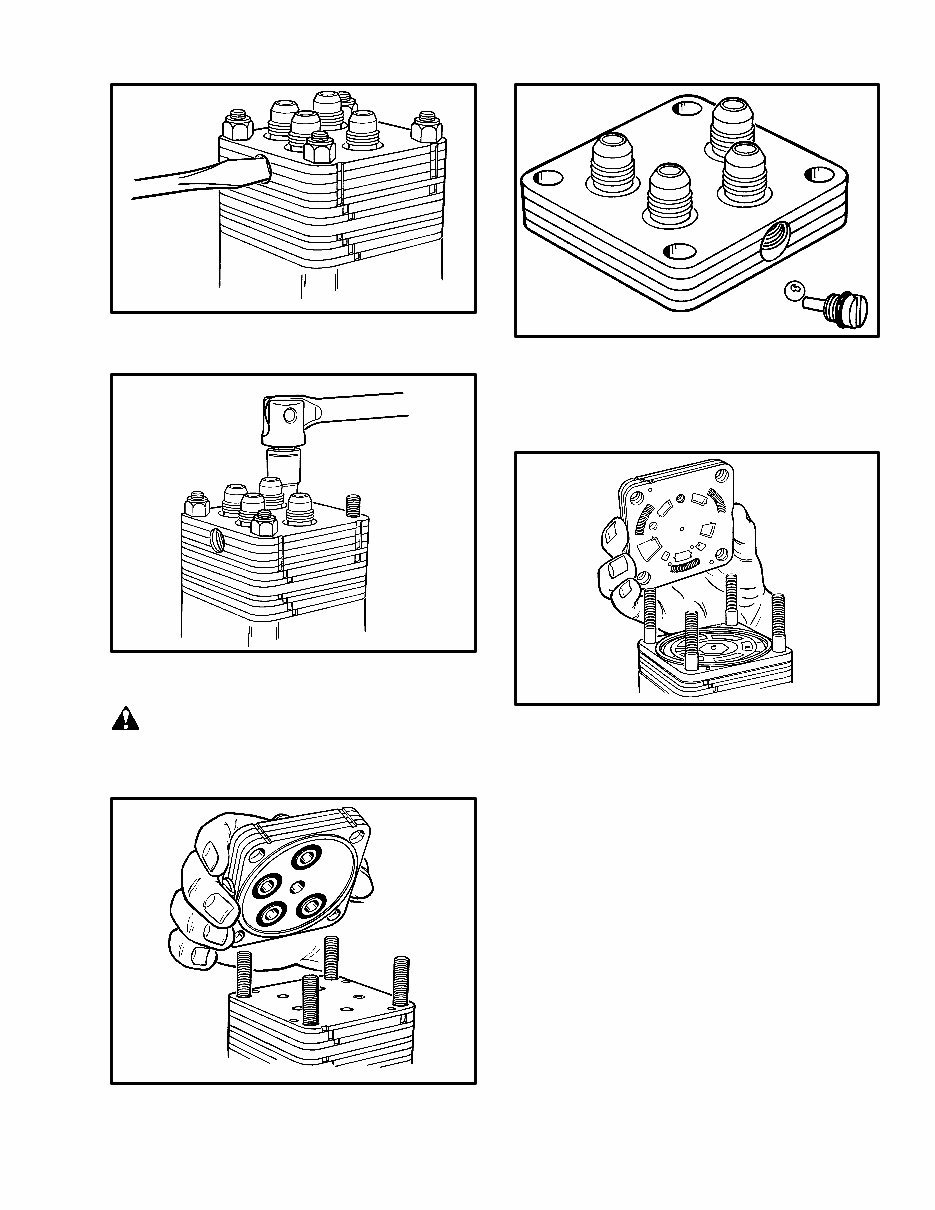
4 FIGURE 4. SERVICE FIXTURE ASSEMBLY 2.00 4.00 8.00 2.00 0.18 45° 2.00 DIA. FOUR HOLES 3/8 (0.375) DIA. EQUALLY SPACED ON A 3.25 DIA. CIRCLE DIMENSIONS SHOWN IN INCHES Make a holder for the steering control unit as shown in the illustration. Do not hold the steering control unit in a vise or the unit can be damaged from distortion. 3.25 DIA. 3.75 0.50 0.625 NOTE: The numbers in parenthesis () in the following steps are a reference to the parts list in FIGURE 2. 1. Remove the contact brush assembly. Remove the screws (45) and washers (46), contact brush assembly (44), and spacer (37) from the upper tube and jacket as- sembly.
5 2. Loosen the plug (6) assembly in the port cover (2) for disassembly after the port cover is removed. 3. Remove the four nuts (1) that hold the port cover (2) to the unit. Do not damage the ports. CAUTION The nuts (1) are a special lock nut. Use only approved parts as replacement nuts. 4. Remove the port cover (2). Discard the four O–rings and the seal ring. 5. Remove the loosened plug (6) and O–ring from the port cover. Do not lose the steel check ball (5) as it falls from its cavity. Inspect the port cover for wear and damage. Replace damaged parts. 6. Carefully lift the port manifold (8) from the unit NOTE: The three springs can become disengaged when the port manifold is removed. Do not permit the loss of the three springs (9). Remove the three springs from the port manifold. In- spect the springs for damage or distortion. NOTE: Keep the three springs from the port manifold separate from the three springs you will remove from the isolator manifold. The three springs in the port man- ifold are 19 mm (0.75 in) in length. The three springs in the isolator manifold are 13 mm (0.50 in) in length. If any of the springs are damaged, the springs in both the port manifold and the isolator manifold must be re- placed. Inspect the port manifold. The rotation of the valve plate will normally polish a pattern in the port manifold. An acceptable part can have this pattern if there are not scratches, grooves, or other damage.
Get the comprehensive Hyster D001 (H1.50XM H1.75XM H2.00XMS Europe) Forklift Service Repair Factory Manual for detailed maintenance and repair guidance. This electronic manual offers a significant advantage over its paper counterpart, allowing you to zoom in on your computer for clear visibility. The manual corresponds with the number of pages printed on the parts, ensuring ease of use.
This manual covers the following models:
Hyster D001 (H1.50XM Europe) Forklift
Hyster D001 (H1.75XM Europe) Forklift
Hyster D001 (H2.00XMS Europe) Forklift
Service Repair Factory Manual Covers:
Brake system
Capacities and specifications
Cooling system
Drive axle
Electrical systems of the mazda m4¨C1.5g gasoline
Electrical systems of the mazda m4¨C2.5d diesel
Electrical systems used on the mazda m4¨C2.0g
Engine
Fasteners
Frame
Gaskets
Gasoline fuel system
Hydraulic system
Instrument cluster
Lpg fuel system
Main control valve
Maintenance schedule
Mast
Single¨Cspeed powershift transmission
Steering axle
Steering control unit
Steering housing and the steering control unit
Tilt cylinders
Wiring schematic
The Hyster D001 (H1.50XM H1.75XM H2.00XMS Europe) Forklift Service Repair Factory Manual is meticulously written in a step-by-step format, making it easy for both professional mechanics and DIY enthusiasts to perform repairs and save on expenses.
File Format: .PDF
Compatible: All Versions of Windows & Mac
Language: English
Requirements: Adobe Reader & Win

 Forklift Service Repair Factory Manual")