


1
INTRODUCTION
GENERAL
This section has the description and the repair instruc-
tions for the engine. Disassembly, cleaning, assembly,
specifications and troubleshooting are included.
WARNING
Some gaskets used in this engine can contain
dangerous fibers. Breathing dust from these fibers is
a cancer or lung disease hazard. Do not create dust!
Use vacuum equipment for asbestos or follow the
cleaning procedure described below.
• Make sure the gasket material is wet with
water or oil to prevent particles in the air.
• Use a hand scraper to remove old gasket mate-
rial. Do not use a power tool or compressed air.
• Discard all asbestos material in a closed con-
tainer while it is still wet.
Put a “DANGEROUS FIBERS” warning label on
the container. Discard dangerous fiber material
safely.
CAUTION
Disconnect the battery cables before doing any
disassembly and repair to the engine or parts of the
electrical system.
The diodes and resistors in the electrical system can
be damaged if the following cautions are not
followed:
• Do not disconnect the battery when the engine
is running. The voltage surge can damage the
diodes and resistors.
• Do not disconnect an electric wire before the
engine is stopped and the switches are “OFF”.
• Do not cause a short circuit by connection of
the electric wires to the wrong terminals.
Make sure a correct identification is made of
the wire before it is connected.
• Make sure a battery is the correct voltage and
polarity before it is connected.
• Do not check for current flow by making a
spark because the electronic components can
be damaged.
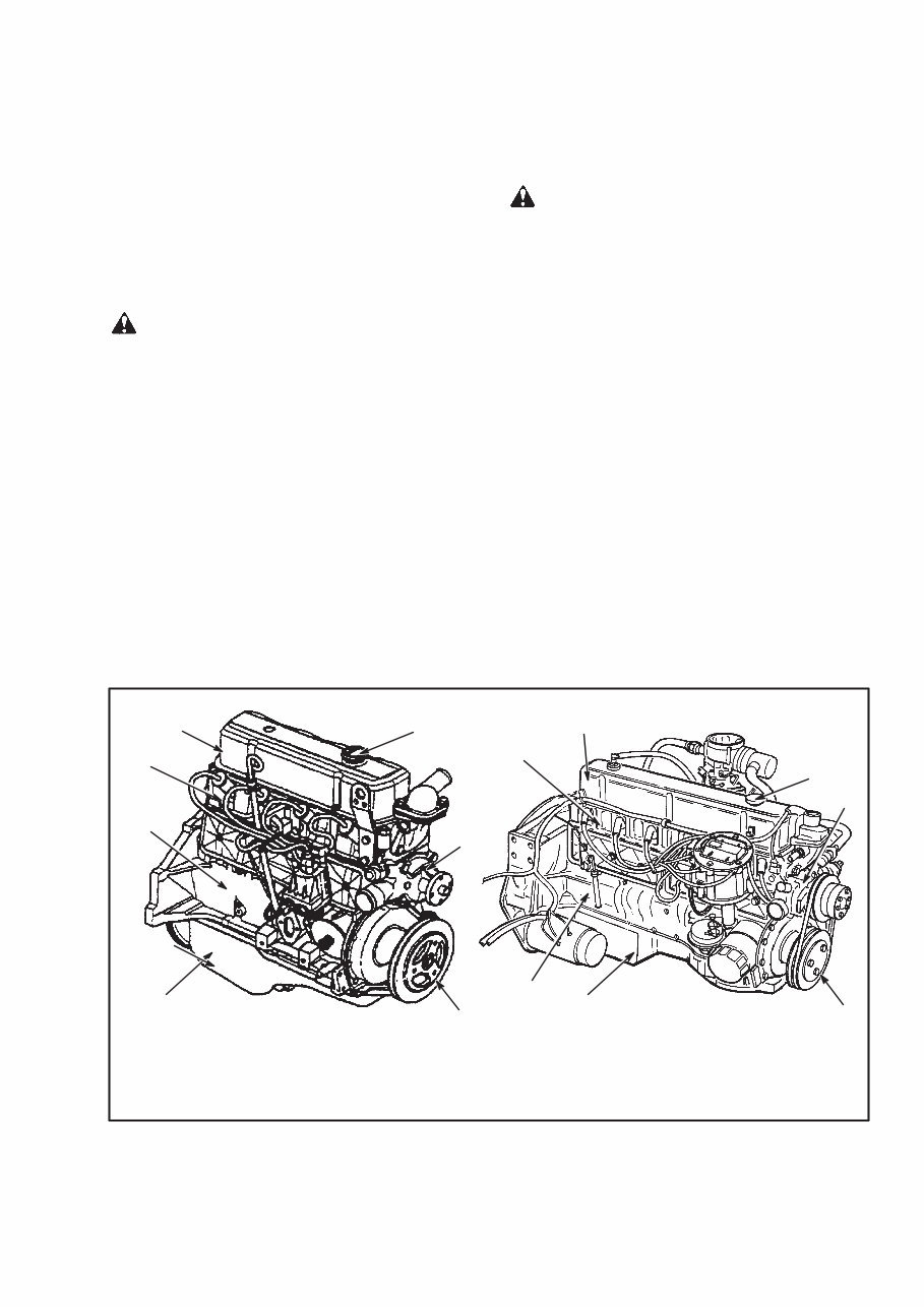
FIGURE 1. GM ENGINES
10569
5. OIL SUMP
6. ENGINE BLOCK
7. CYLINDER HEAD ASSEMBLY
4–153, 4–181 AND 3.0L ENGINES
6–250 ENGINE
1. ROCKER ARM COVER
2. FILL CAP FOR ENGINE OIL
1 2
3
4
5
6
7
3. WATER PUMP
4. VIBRATION DAMPENER
4
5
2
1
7
6
3

2
DESCRIPTION
The GM engines described in this section are the four
cylinder and six cylinder models that have the arrange-
ment of the cylinders in a straight line. These engines
have a similar design. The number one cylinder for these
engines is toward the cooling fan. These engines can
have either a gasoline or a LPG fuel system.
The GM 4–153 engine is used in some models of 2.00 to
3.00 ton (4000 to 6000 lb) capacity lift trucks from June
1975 until June 1990. During 1990, production of the
GM 4–153 engine was stopped and it was replaced with
variations of the GM 4–181 engine. The GM 4–181 en-
gine is also used in some models of 2.00 to 3.00 ton
(4000 to 6000 lb) capacity lift trucks beginning in 1978.
The two engines are the same design except for different
displacements. The GM 4–181 engines installed in the
lift trucks with serial code B187 [S2.00–3.00XL
(S40–60XL)] beginning in 1990 have a different cam-
shaft than the GM 4–181 engines used in the lift trucks
with other serial codes.
The GM 4–181 engines installed in the lift trucks with
serial codes C187 [S2.00–3.00XL (S40–60XL)] and se-
rial codes B177 and C177 [H2.00–3.00XL
(H40–60XL)] are the same engine.
The GM 3.0L engine is a later model of the 4–181 en-
gine. It is used in the S/H2.00–3.20XM (S/H40–65XM)
lift trucks.
The GM 6–250 engine is used in some models of 3.00 to
7.50 ton (6000 to 15 000 lb) capacity lift trucks from
1975 until 1988.
A camshaft in the engine block operates the overhead
valves with push rods. A cast iron crankshaft gear drives
a camshaft gear. The cam lobes are hardened and have a
taper with the high side toward the rear of the engine.
The valve lifters have a rounded surface where they con-
tact the cam lobes. This combination of surfaces causes
the valve lifters to rotate during engine operation. All of
the engines have hydraulic valve lifters.
Each rocker arm rotates on a pivot ball stud fastened to
the cylinder head. The valve guides and valve seats are
part of the cylinder head. The exhaust valve seats are in-
duction hardened.
The crankshaft in the four cylinder engines has five
main bearings. The crankshaft in the six cylinder engine
has seven main bearings. The rear main bearing in all
engines is the thrust bearing.
The pistons are aluminum alloy and have three piston
rings. The two compression rings each have a different
design. Some oil control rings have three parts that must
be assembled when the oil control ring is installed on the
piston.
The specifications for engine repair are shown in EN-
GINE SPECIFICATIONS at the end of this section.
REMOVAL AND INSTALLATION OF THE
ENGINE
NOTE: The removal and installation procedures for the
engine and transmission are not included in this section.
See the section, THE FRAME for the model of lift
truck for these procedures.
CYLINDER HEAD AND VALVE
MECHANISM
Cylinder Head, Removal
1. Disconnect the battery cables at the battery.
2. Drain the cooling system.
3. Disconnect and remove the coolant hose from the
housing for the thermostat.
4. Remove or disconnect the air filter.
5. Disconnect the PCV valve.
6. Disconnect the wires and hoses fastened to brackets
on the rocker arm cover.
7. Disconnect the spark plug wires.
8. Disconnect the linkages, fuel lines, and hoses for the
fuel system.
9. Disconnect the exhaust pipe at the exhaust manifold
and remove the intake and exhaust manifolds.
10. If necessary, remove the alternator and bracket.
11. Remove the dipstick tube for engine oil.
12. Remove the rocker arm cover.
NOTE: Keep the rocker arm assemblies and the push
rods in order so that they will be installed in the same po-
sition.
3
13. Remove the rocker arms and the push rods.
14. Loosen the cylinder head bolts in two or three steps.
Do not completely loosen the cylinder head bolts during
the first sequence. Remove the cylinder head bolts. Re-
move the cylinder head and the gasket.
Cylinder Head, Disassembly
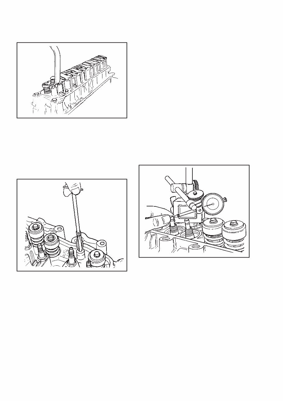
1. Use a compressor tool to compress the valve springs
and remove the retainers. See FIGURE 2. and
FIGURE 3. Release the compressor tool and remove the
spring cap, (rotators, when used), oil shield, and valve
springs. Remove the oil seal and any shims from the
springs.
2. Remove the valves from the cylinder head and put
them in a rack so that the valves can be installed again in
their same positions in the cylinder head.
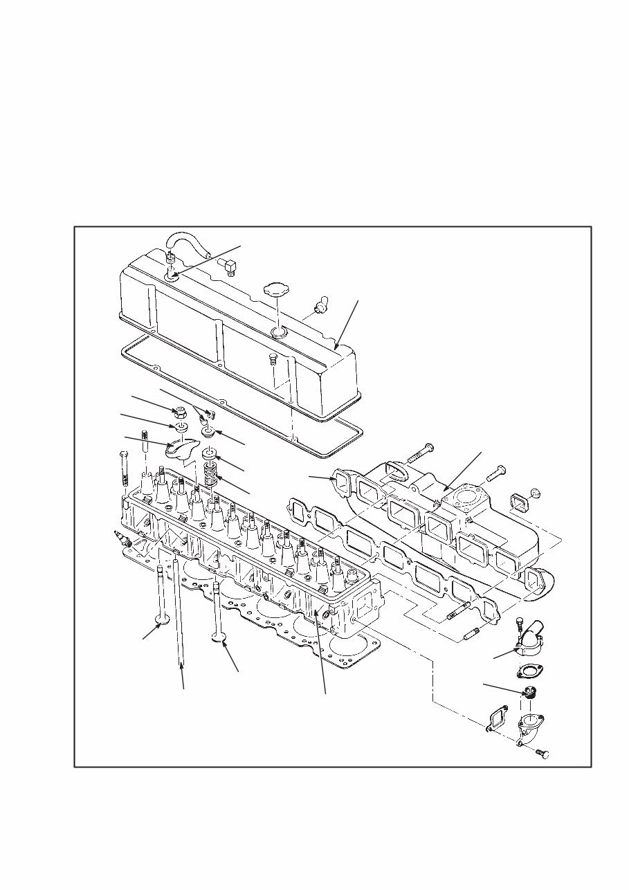
FIGURE 2. CYLINDER HEAD
8908
1. PCV VALVE
2. ROCKER ARM COVER
3. INTAKE MANIFOLD
4. OUTLET
5. THERMOSTAT
6. CYLINDER HEAD
7. INTAKE VALVE
8. PUSH ROD
9. EXHAUST VALVE
10. VALVE SPRING
11. EXHAUST MANIFOLD
12. SHIELD
13. SPRING CAP
14. ROCKER ARM
15. BALL
16. NUT
17. RETAINER
1
2
3
4
5
6
7
8
9
10
11
12
13
14
15
16
17
GM 6–250 SHOWN
4
FIGURE 3. COMPRESS THE VALVE SPRINGS
Cleaning And Inspection
1. Clean the carbon from the combustion chambers and
the valve ports.
2. Clean the valve guides. Use a tool as shown in the ex-
ample in FIGURE 4.
FIGURE 4. TOOL FOR CLEANING THE VALVE
GUIDES
3. Clean the push rods and rocker arms.
4. Clean the surfaces of the cylinder head where the gas-
kets fit.
6. Inspect the cylinder head for cracks in the exhaust
ports, combustion chambers, and external surfaces.
7. Inspect the valves for burned or damaged areas in the
seat surfaces. Inspect for cracks and damaged or worn
valve stems.
8. Check the clearance of each valve stem in its valve
guide. Use the following procedure:
a. Use a micrometer to measure the diameter of the
valve stem in three places: top, center, and bot-
tom. The stems of exhaust valves have a small ta-
per. The end of the valve stem near the spring is
approximately 0.0025 mm (0.001 in) larger than
the diameter near the valve head. Use a hole
gauge to measure the bore in the valve guide.
b. Another method of measuring the clearance of
the valve stem in its valve guide is to use a dial in-
dicator as shown in FIGURE 5. Put the dial indi-
cator so that it can measure the side–to–side
movement of the valve stem. Lower the valve
away from its valve seat approximately 3 mm
(0.1 in). Move the valve stem from side–to–side
and check the measurement on the dial indicator.
FIGURE 5. CHECK THE CLEARANCE
BETWEEN VALVE GUIDE AND VALVE
12686
c. The maximum clearance between the valve
stems and their valve guides is shown in the EN-
GINE SPECIFICATIONS.
d. If the clearance between the valve stem and its
valve guide is greater than the specification, a
valve with an oversize stem must be installed.
Use a reamer to make the bore the correct diame-
ter for the next oversize valve. See the Parts
Manual for oversize valves.
9. Use a valve spring tester to check the valve springs. A
typical tester is shown in FIGURE 48. The specifica-
5
tions for the valve springs are shown in the ENGINE
SPECIFICATIONS.
10. Inspect the rocker arm bolts for wear and damage.
Valves And Valve Seats
The condition and alignment of the valves to their valve
seats is important so that the engine will operate correct-
ly. Before any work is done on the valve seats, make sure
the clearance of the valve stems in their valve guides is
within specifications.
A correction for minimum wear and damage to the valve
and seat can be done by a process called “lapping”.
When the valve seats are “lapped”, keep the valve seats
within the specifications. Make sure all of the lapping
compound is removed from the valve and valve seat
when the process is completed.
NOTE: Some engines have valve seats that can be re-
placed. If the valve seats cannot be repaired or replaced,
install a new cylinder head.
Damaged valve seats can be repaired with a cutter tool.
If the valve seat can not be repaired so that the valve
depth is within specifications, the cylinder head must be
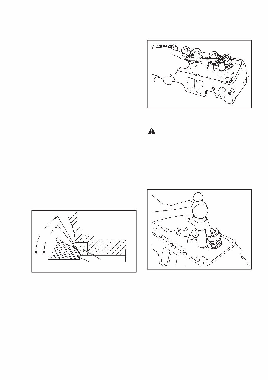
replaced. The specifications for the valve seats are
shown in FIGURE 6.
FIGURE 6. VALVE SEAT SPECIFICATIONS FOR
INTAKE AND EXHAUST VALVES
1. VALVE SEAT
2. MINIMUM THICKNESS
OF VALVE HEAD IS
0.80 mm (0.031 in)
46°
45°
2
1
Studs For The Rocker Arms
Replace a stud that has damaged threads or is loose in the
cylinder head. See the Parts Manual for oversize studs.
1. Remove the old stud. Install a spacer, flat washer, and
nut to the damaged stud. Use a wrench to remove the
damaged stud. See FIGURE 7.
FIGURE 7. REMOVE A STUD FOR A ROCKER
ARM
CAUTION
Do not try to install an oversize stud without reaming
the stud hole to the new size. Installation of an over-
size stud without reaming the stud hole can cause
cracks in the cylinder head.
2. Use a reamer of the correct size for the new oversize
stud. Apply SAE 90 lubricant to the new stud during in-
stallation. Install the new stud as shown in FIGURE 8.
FIGURE 8. INSTALLATION OF A STUD FOR A
ROCKER ARM
Hydraulic Valve Lifters, Replacement
The hydraulic valve lifters normally do not need service
unless they are dirty or damaged. The hydraulic valve
lifters must be clean to operate correctly. If the lifters
make noise or do not operate correctly, replace them.
The lifters can be removed with a flexible magnet after
the push rods are removed.
You're Reading a Preview
What's Included?
 Lifetime Access
Fast Download Speeds
Offline Viewing
Access Contents & Bookmarks
Full Search Facility
Print one or all pages of your manual
$41.99
Hyster C177 (H3.00XL Europe) Forklift Service Manual
Viewed 46 Times Today

What's Included?
Lifetime Access
Fast Download Speeds
Offline Viewing
Access Contents & Bookmarks
Full Search Facility
Print one or all pages of your manual
$41.99

Secure transaction
What's Included?
Lifetime Access
Fast Download Speeds
Offline Viewing
Access Contents & Bookmarks
Full Search Facility
Print one or all pages of your manual
Description
This manual contains maintenance and repair procedures for the Hyster C177 (H3.00XL Europe) Forklift.
- Covers the following models:
- Hyster C177 (H3.00XL Europe) Forklift Service Repair Factory Manual
Service Repair Factory Manual Covers:
- Alternator
- Brake system
- Capacities and specifications
- Cooling system
- Drive axle
- Electrical systems for the isuzu c¨C240 (2.4l),4jb1 (2.8l) and 4jg2 (3.1l) diesel engines used on the h2.00¨C3.20xm (h40¨C65xm) units
- Engine and the fuel system
- Engine
- Fasteners
- Frame and some connected parts
- Gauges
- Hydraulic pump
- Hydraulic system schematic
- Lpg fuel system
- Maintenance schedule
- Mast
- Mazda m4-121g engine
- Microprocessor spark timing system (msts)
- Rochester
- Single¨Cspeed powershift transmission
- Starter
- Steering axle
- Steering control unit
- Steering system
- Carburetor mazda m4-121g engine
- Electrical systems for the isuzu c240 (2.4l) diesel engine
- Electrical systems of the mazda m4¨C121g gasoline or lpg engine
- Hydraulic system and the gear pump assembly
- Main control valve and the auxiliary solenoid valve used in the hydraulic system
- Tilt cylinders
- Transmission
Hyster C177 (H3.00XL Europe) Forklift Service Repair Factory Manual is written step by step in details, so you become very easy to repair by yourself. It can save your expenses.
Do not hesitate, after your payment, you will immediately get the manual.
File Format:
- Compatible: All Versions of Windows & Mac
- Language: English
- Requirements: Adobe Reader


