ÿ
u
MA MM
ELECTRIC
N40-45-50EA
N40-45ER
EiinrMtiK
Hyster Easy Language Program
i®DTD®Ca
852310
©1991 HYSTER COMPANY
5/91
ÿ
L2 Page 1
ÿ
U
HYSTER
23
HYSTER
ni
SERIAL CODE C1 38
SIB
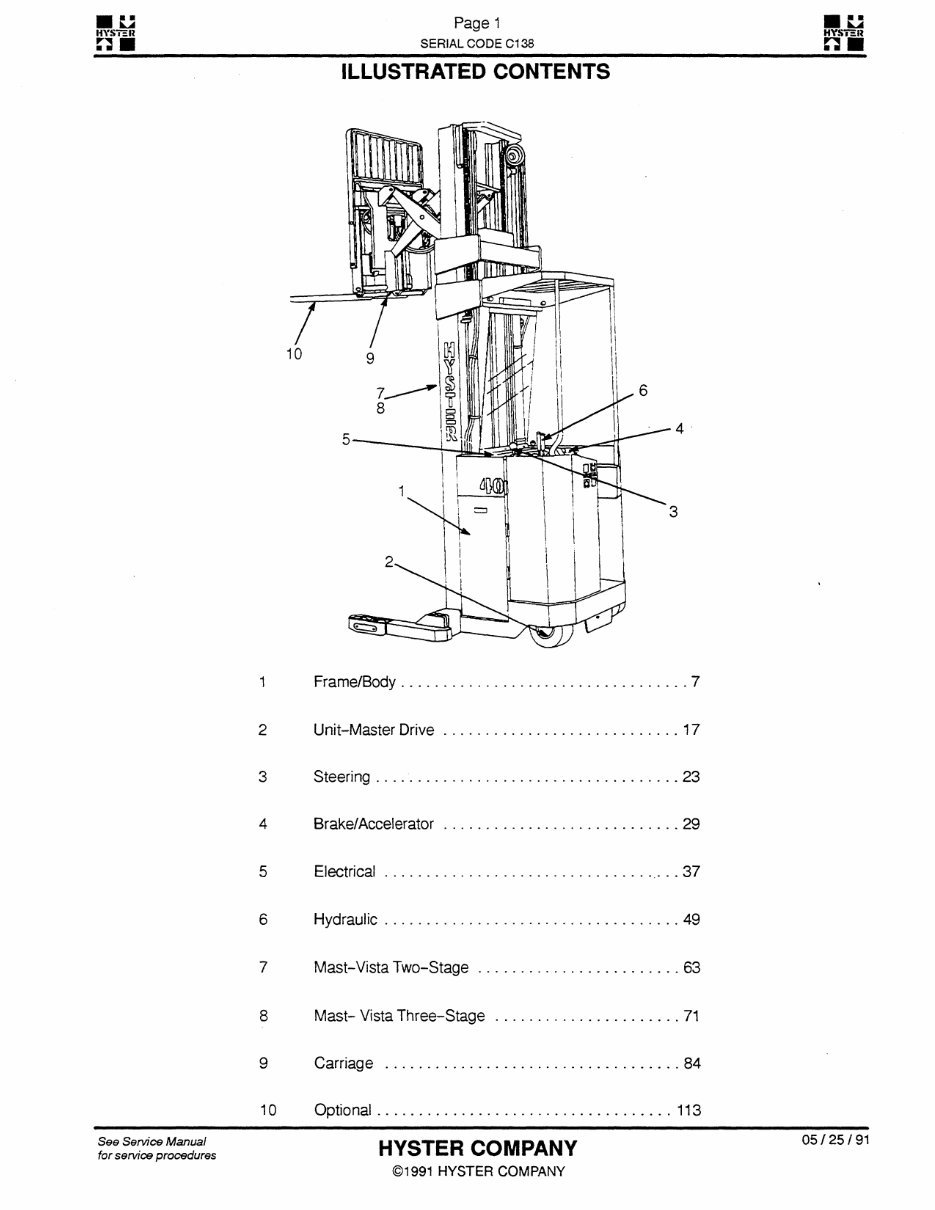
ILLUSTRATED CONTENTS
1 Frame/Body 7
2 Unit-Master Drive 17
3 Steering 23
4 Brake/Accelerator 29
5 Electrical ...37
6 Hydraulic 49
7 Mast- Vista Two-Stage 63
8 Mast- Vista Three-Stage 71
9 Carriage 84
10 Optional 113
See Service Manual
for service procedures
HYSTER COMPANY
©1991 HYSTER COMPANY
05/25/91
ÿ
EL2 Page 2
ÿ
JL2
HYSTHR
W
HYS7SH
n M
_ SERIAL CODE C138 _ Q M
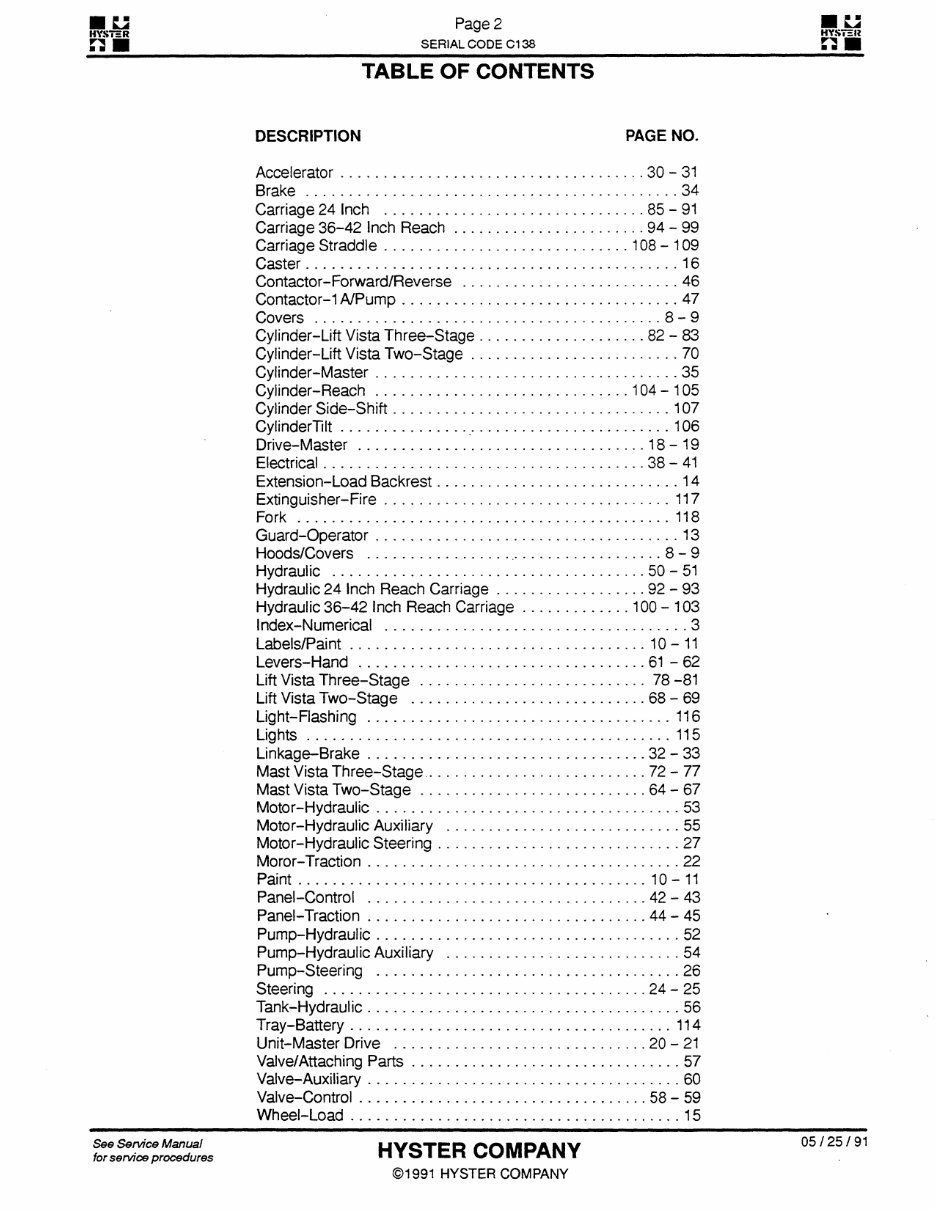
TABLE OF CONTENTS
DESCRIPTION PAGE NO.
Accelerator 30-31
Brake 34
Carriage 24 Inch 85-91
Carriage 36-42 Inch Reach 94-99
Carriage Straddle 1 08 -
1 09
Caster 16
Contactor-Forward/Reverse 46
Contactor-1 A/Pump 47
Covers 8-9
Cylinder-Lift Vista Three-Stage 82-83
Cylinder-Lift Vista Two- Stage 70
Cylinder-Master 35
Cylinder- Reach 1 04 - 1 05
Cylinder Side-Shift 1 07
CylinderTilt 106
Drive-Master 18-19
Electrical 38-41
Extension-Load Backrest 14
Extinguisher-Fire 117
Fork 118
Guard-Operator 13
Floods/Covers 8-9
Hydraulic 50-51
Hydraulic 24 Inch Reach Carriage 92-93
Hydraulic 36-42 Inch Reach Carriage 1 00 - 1 03
Index-Numerical 3
Labels/Paint 10-11
Levers-Hand 61-62
Lift Vista Three-Stage 78 -81
Lift Vista Two-Stage 68-69
Light-Flashing 116
Lights 115
Linkage-Brake 32-33
Mast Vista Three-Stage 72-77
Mast Vista Two-Stage 64-67
Motor-Hydraulic 53
Motor-Hydraulic Auxiliary 55
Motor-Hydraulic Steering 27
Moror-Traction 22
Paint 10-11
Panel-Control . 42-43
Panel-Traction 44-45
Pump-Hydraulic 52
Pump-Hydraulic Auxiliary 54
Pump-Steering 26
Steering 24-25
Tank-Hydraulic 56
Tray-Battery 114
Unit-Master Drive 20-21
Valve/Attaching Parts 57
Valve-Auxiliary 60
Valve-Control 58-59
Wheel-Load 15
See Service Manual
for service procedures
HYSTER COMPANY
©1991 HYSTER COMPANY
05/25/91
ÿ
EJS Page 3
ÿ
L3
HYST5R
3
HYSTSR
n
ÿ SERIAL CODE C1 38 ÿ
9
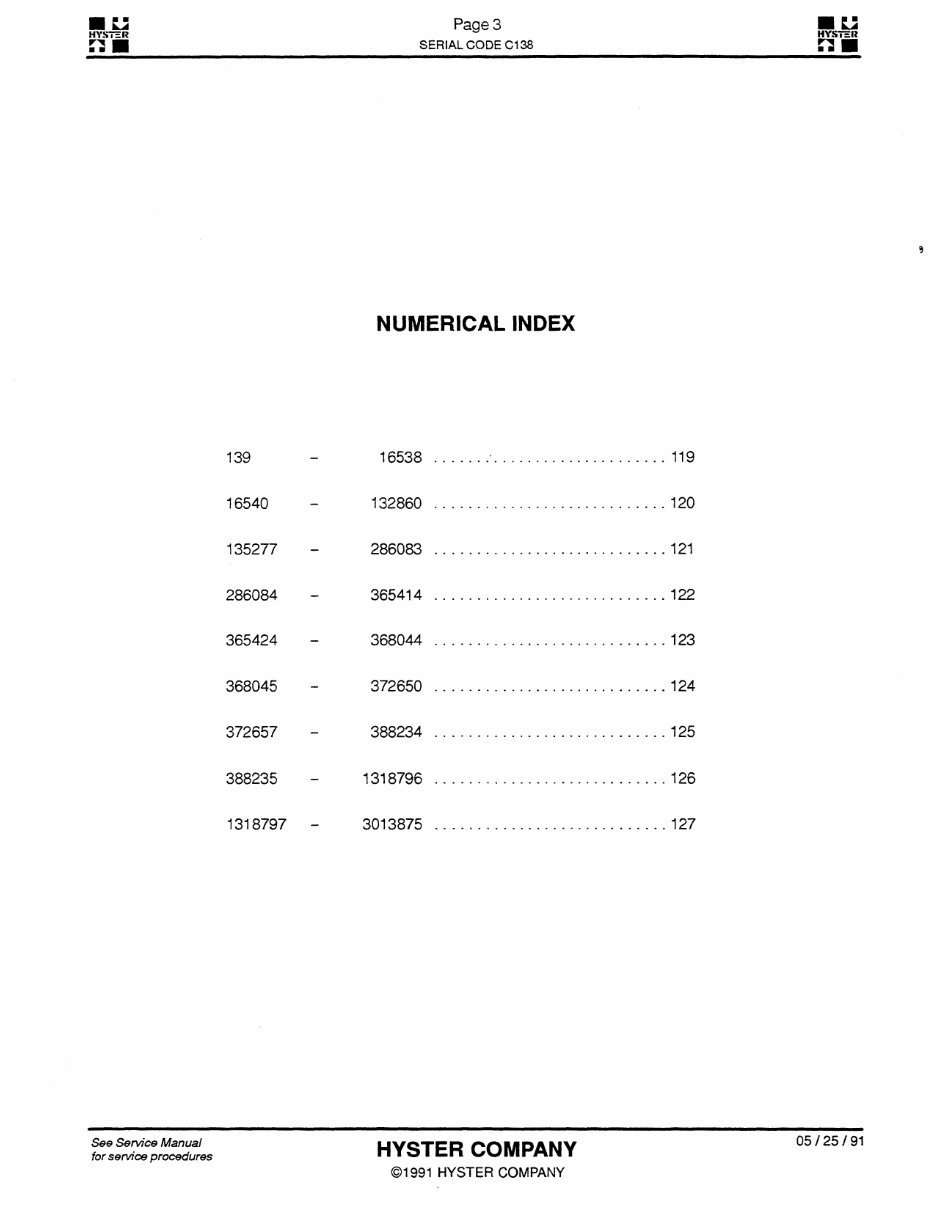
NUMERICAL INDEX
139 - 16538 119
16540 - 132860 120
135277 - 286083 121
286084 - 365414 122
365424 - 368044 123
368045 - 372650 124
372657 - 388234 125
388235 - 1318796 126
1318797 - 3013875 127
See Service Manual
for service procedures
HYSTER COMPANY
©1991 HYSTER COMPANY
05/25/91
ÿ
EJS Page 4
HVSTHR HVSTER
ÿ SERIAL CODE C1 38 ÿ
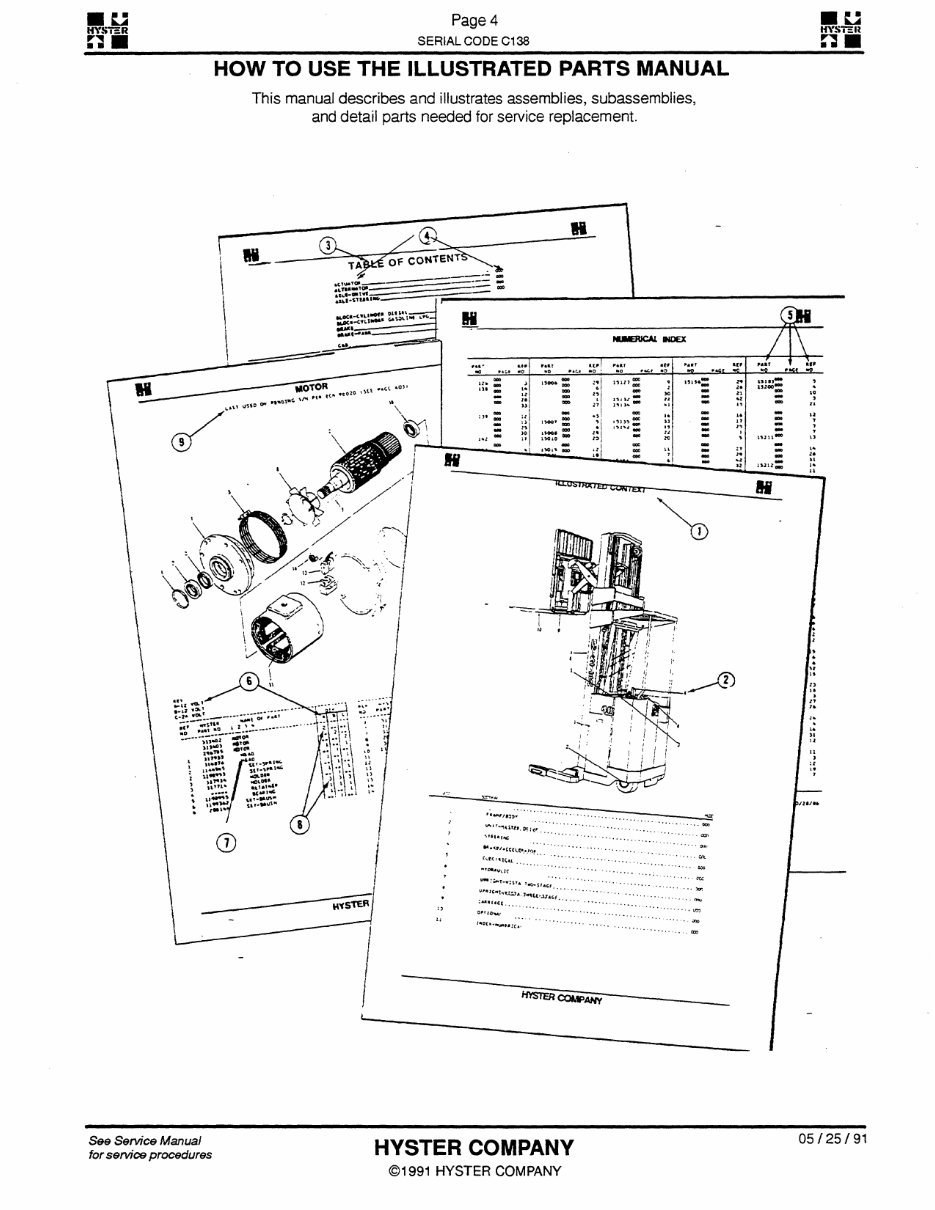
HOW TO USE THE ILLUSTRATED PARTS MANUAL
This manual describes and illustrates assemblies, subassemblies,
and detail parts needed for service replacement.
OF CONTENT!
tCTWTO*
—
AlTM"*TOJ_—
motor
»»•«>
»!?•»»
u«"'
u"»»
Vi-wi
3/U/M
'"TU-J/4tp
See Service Manual
for service procedures
HYSTER COMPANY
©1991 HYSTER COMPANY
05/25/91
ÿ
Li Page 5
ÿ
Li
HYSTHB
3
HYSTHIJ
n
ÿ SERIAL CODE C1 38 ÿ
WHEN THE PART NUMBER AND THE NEXT
HIGHER ASSEMBLY IS NOT KNOWN:
1 . Determine the functionofthe part required. Turn to the
Illustrated Index immediately behind the front
cover. Choose the general area of reference most
likely to include the part.
2. Find the page number for the reference number you
choose and turn to that page. Use the division index
to determine the assembly which would normally
contain the part required. Then locate the part on the
assembly breakdown page.
WHEN THE PART NUMBER IS NOT KNOWN AND
THE NEXT HIGHER ASSEMBLY IS KNOWN:
3. Determine the assembly the required part is used on.
Turn to the Table of Contents immediately following
the Illustrated Index.
4. Locate the assembly the required part is used on and
turn to the page indicated for that assembly. Then lo¬
cate the part on the assembly breakdown page.
WHEN THE PART NUMBER IS KNOWN:
5. Use the Numerical Index at the backof the manual to
find the part number. Turn to the page listed and lo¬
cate the part as indicated by the reference number.
GENERAL:
6. Keys are used to show effective serial numbers for two
or more similar assemblies, RH and LH assembly
parts, different configurations, etc.. Select the appro¬
priate key, "A", "B", "C", or "D", which will indicate the
column in which the part quantity can be found.
7. Indented descriptions under "Name of Parfare used
to indicate assemblies and sub-parts of assemblies.
In the example (Item 7), HEAD is a sub-part of the
major assembly MOTOR, and SET-SPRING is one
of several sub-parts of the assembly HEAD.
8. Quantities shown are for one assembly. Note that two
assemblies are shown, but the quantities of the sub¬
parts are indicated as three. This means three per
assembly.
9. Engineering change notice (ECN) numbers for pend¬
ing serial numbers are shown to allow for the inclu¬
sion of the most current parts information. Contact
your local dealer for Hyster lift truck serial number in¬
formation listed by ECN number.
Ordering parts:
When ordering replacement parts, give the unit serial number,
part number, name of part, and quantity required.
For any further information on parts, service, or ordering, consult your local dealer for Hyster lift trucks.
See Service Manual
for service procedures
HYSTER COMPANY
©1991 HYSTER COMPANY
05/25/91
ÿ
IZ
HYSTER
n
ÿ
Page 6
SERIAL CODE C138
ÿ
u
HYSTER
n
ÿ
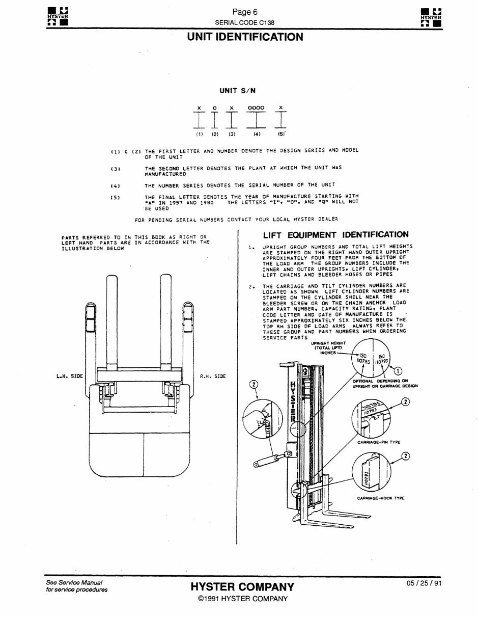
UNIT IDENTIFICATION
UNIT S/N
A U A
III
(1) (2) 13)
OOOO
(4)
A
I
(SI
(1) C (21 The first letter ano number denote the
design SERIES and model
OF THE UNIT
(3) THE SECOND LETTER DENOTES THE PLANT AT WHICH THE UNIT WAS
manufactured
(4) THE NUMBER SERIES OENOTES THE SERIAL NUMBER OF THE UNIT
(5) THE FINAL LETTER DENOTES THE YEAR OF MANUFACTURE STARTING WITH
"A" IN 1957 AND I960 THE LETTERS "I". "O". AND "Q" WILL NOT
BE USED
FOR PENDING SERIAL NUMBERS CONTACT YOUR LOCAL HYSTER DEALER
LIFT EQUIPMENT IDENTIFICATION
PARTS REFERREO TO IN THIS BOOK AS RIGHT OR
LEFT HAND PARTS ARE IN ACCORDANCE WITH THE
ILLUSTRATION BELOW
L.H. SIDE
0p IÿO
J
V J
R.H. SIDE
UPRIGHT GROUP NUMBERS AND TOTAL LIFT HEIGHTS
ARE STAMPED ON THE RIGHT HAND OUTER UPRIGHT
APPROXIMATELY FOUR FEET FROM THE BOTTOM OF
THE LOAD ARM THE GROUP NUMBERS INCLUDE THE
INNER ANO OUTER UPRIGHTS? LIFT
CYLINDER,
LIFT CHAINS AND BLEEDER HOSES OR PIPES
THE CARRIAGE AND TILT CYLINDER NUMBERS ARE
LOCATED AS SHOWN LIFT CYLINDER NUMBERS ARE
STAMPED ON THE CYLINDER SHELL NEAR THE
BLEEDER SCREW OR ON THE CHAIN ANCHOR LOAD
ARM PART NUMBER, CAPACITY RATING, PLANT
COOE LETTER AND DATE OF MANUFACTURE IS
stamped approximately six inches below the
TOP RH side of load arms
always refer to
THESE GROUP AND PART NUMBERS WHEN ORDERING
SERVICE PARTS
UPRIGHT HEIGHT
(TOTAL UFT)
INCHES
-
OPTIONAL DEPENDHQ ON
UPRIOHT on CARRIAGE DESION
CARRIAGE-PIN TYPE
CARRIAGE-HOOK TYPE
See Service Manual
for service procedures
HYSTER COMPANY
©1991 HYSTER COMPANY
05/25/91
ÿ
:i Page 7
ÿ
U
HYSTER
a
HWT3R
H
SERIAL CODE C1 38
SHS
ÿ
FRAME/BODY
Caster 16
Extension-Load Backrest 14
Guard-Operator 13
Hoods/Covers 8-9
Labels/Paint 10-11
Publications 12
Wheel-Load 15
See Service Manual
for service procedures
HYSTER COMPANY
©1991 HYSTER COMPANY
05/25/91
ÿ
kJ Page 8
ÿ
Li
HYSTER
ÿ
HYSTER
[j U
_ SERIAL CODE C1 38 _ ÿÿ
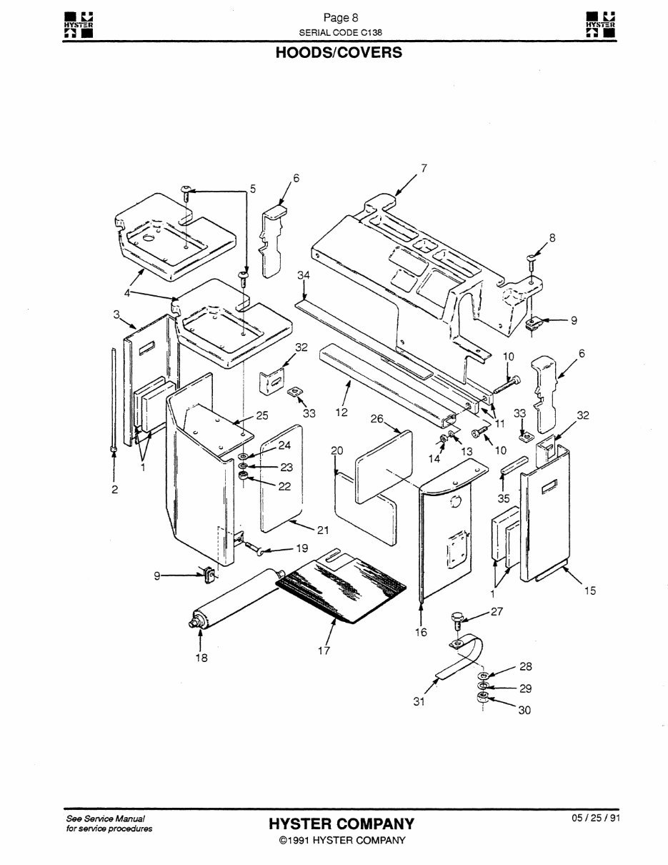
HOODS/COVERS
See Service Manual
for service procedures
HYSTER COMPANY
©1991 HYSTER COMPANY
05/25/91
ÿ
Li Page 9
ÿ
U
HYSTER
3
HYSTER
H
ÿ SERIAL CODE C1 38
ST2
ÿ
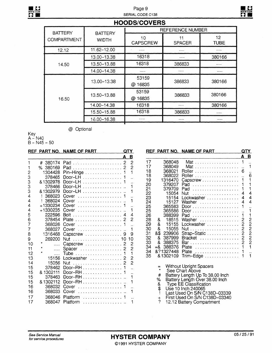
HOODS/COVERS
BAI I bRY
COMPARTMENT
BATTERY
WIDTH
REFERENCE NUMBER
10
CAPSCREW
11
SPACER
12
TUBE
12.12
11.62-12.00
14.50
13.00-13.38 16318 380166
13.50-13.88 16318 386833
14.00-14.38
16.50
13.00-13.38
53159
@ 16835
386833 380166
13.50-13.88
53159
@ 16835
386833 380166
14.00-14.38 16318 380166
15.50-15.88 16318 386833
16.00-16.38
@ Optional
Key
A - N40
B - N45 - 50
REF PART NO. NAME OF PART
_
QTY
_
A B
1 # 380174 Pad . . 2 2
1 % 380169 Pad 2 2
2 1304428 Pin-Hinge 1 1
3 378465 Door-LH 1 ..
3 & 1302978 Door-LH 1 ..
3 378466 Door-LH 1
3 & 1302979 Door-LH 1
4 ! 368023 Cover 1 ..
4 ! 368024 Cover 1
4 +1330234 Cover 1 ..
4 +1330235 Cover 1
5 222596 Bolt 4 4
6 378454 Plate 2 2
7 368026 Cover 1 ..
7 368027 Cover 1
8 1316468 Capscrew 9 9
9 269200 Nut 10 10
10
*
.....
Capscrew 2 2
11
*
.....
Spacer 2 2
12
*
..... Tube 1 1
13 15156 Lockwasher 2 2
14 15056 Nut 2 2
15 378462 Door-RH 1 ..
15 & 1302111 Door-RH 1 ..
1 5 378463 Door-RH 1
15 & 1302112 Door-RH 1
16 368032 Cover 1 ..
16 368033 Cover 1
17 368046 Platform 1 ..
17 368047 Platform 1
REF PART NO. NAME OF PART
_
QTY
_ A_B
17 368048 Mat 1 ..
17 368049 Mat 1
18 368021 Roller 6 ..
18 368022 Roller 6
19 1316470 Capscrew 1 1
20 379207 Pad 1 1
21 379709 Pad 1 1
22 15054 Nut 4 4
23 15154 Lockwasher 4 4
24 15127 Washer 4 4
25 365583 Door 1 ..
25 365586 Door 1
26 388399 Pad 1 1
28 & 18515 Washer 2 2
29 & 15155 Lockwasher 2 2
30 & 15055 Nut 2 2
31 &$ 239906 Strap-Static 2 2
32 8c 387999 Bracket 2 2
33 8c 388375 Bar 2 2
34 =8c 388376 Plate 1 1
34 &? 1327448 Plate 1 ..
35 8c 13021 09 Trim-Edge 1 1
= Without Upright Spacers
*
See Chart Above
# Battery Length Up To 38.00 Inch
% Battery Length Over 38.00 Inch
8c Type EE Classification
$ Use 10 Inch 240065
! Last Used On S/N C1 38D-03339
+
First Used On S/N C1 38D-03340
? 12.12 Battery Compartment
See Service Manual
for service procedures
HYSTER COMPANY
©1991 HYSTER COMPANY
05/25/91
You're Reading a Preview
What's Included?
Lifetime Access
Access PDF Contents & Bookmarks
Print one or all pages of your manual
Add to Cart
$31.99
$41.99

 Parts Manual")