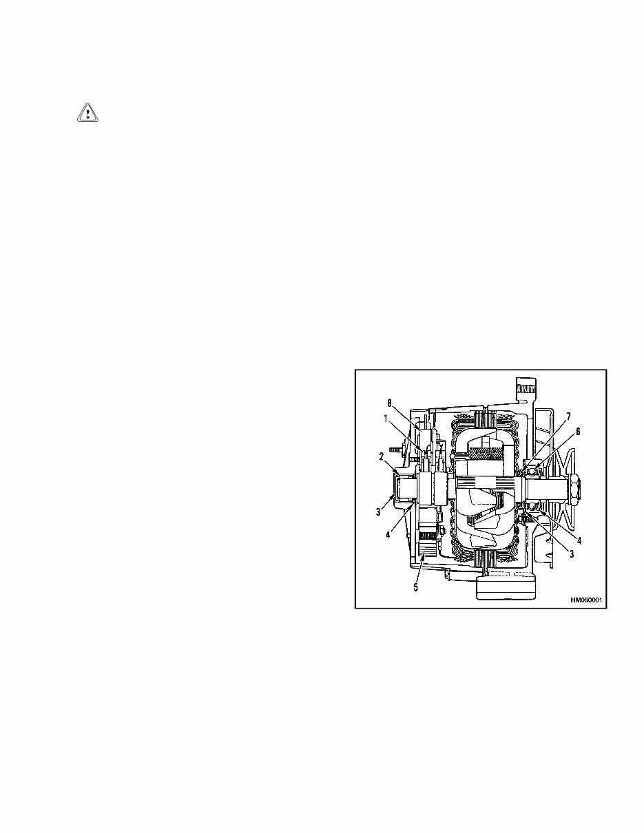
2200 SRM 2 Description General CAUTION When using an arc welder, always disconnect the ground lead from the lift truck battery to prevent alternator or battery damage. Attach the welding ground clamp as close to the weld area as possible to prevent welding current from damaging the bearings. The diodes and resistors in the electrical sys- tem can be damaged if the following cautions are not followed: • Do not disconnect the battery when the en- gine is running. The voltage surge can dam- age the diodes and resistors in the electrical system. • Do not disconnect an electric wire before the engine is stopped and the switches are OFF. • Do not cause a short circuit by connecting the electric wires to the wrong terminals. Make sure a correct identification is made of the wire before it is connected. • Make sure a battery is the correct voltage and polarity before it is connected. • Do not check for current flow by making a spark because the electronic components can be damaged. NOTE: Information on alternators manufactured outside the United States is in the SRM (Service Repair Manual) sections for lift trucks that use those alternators. This section has a description and the repair proce- dures for the alternator with a voltage regulator as part of the alternator. Description NOTE: For this SRM section, the alternators are in two groups: Type A and Type B. The two types are very similar, but the Type A alternators have a set of three diodes (diode set) as well as the diode bridge. The Type B alternator has zener diodes as part of the diodes in the diode bridge. This alternator does not have a diode set, but does have an additional fan inside the rear housing. The basic operation of both types is very similar. The alternator generates an alternating current when the engine is running. The alternator is either ON or OFF. The alternator generates maximum current when it is ON and no current when it is OFF. The regulator switches the alternator between ON and OFF to get the average current needed to charge the battery. Alternator output is directly changed by engine speed and rotor field current. The alternating current is changed to a direct current by the diode bridge inside the alternator. The alternator has these parts (see Figure 1 and Fig- ure 2): A stator A rotor A diode bridge A diode set (Type A only) Two end housings or frame halves A solid-state voltage regulator NOTE: DELCO TYPE A SHOWN. 1. BRUSH ASSEMBLY 2. ROLLER BEARING 3. GREASE RESERVOIR 4. LIP SEAL 5. DIODE BRIDGE 6. BALL BEARINGS 7. FELT SEAL 8. REGULATOR Figure 1. Alternator Cross Section 1
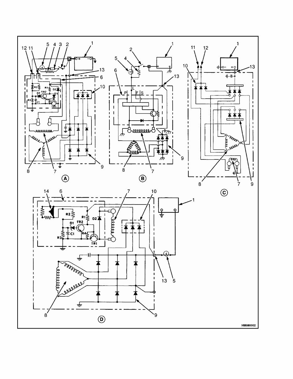
2200 SRM 2 Alternator Repair Legend for Figure 2 NOTE: LEECE-NEVILLE NOT AVAILABLE, SIMILAR TO THOSE SHOWN. A. DELCO TYPE A (SMALL CAPACITY LIFT TRUCKS) B. DELCO TYPE B C. MOTOROLA TYPE A D. DELCO TYPE A (LARGE CAPACITY LIFT TRUCKS) 1. BATTERY 2. KEY SWITCH 3. FUSE 4. RESISTOR 5. INDICATOR LIGHT OR AMMETER 6. VOLTAGE REGULATOR 7. ROTOR FIELD 8. STATOR 9. DIODE BRIDGE 10. DIODE SET 11. FIELD TERMINAL 12. REGULATOR TERMINAL 13. OUTPUT (BAT) TERMINAL 14. VOLTAGE ADJUSTMENT The direct current from the diodes of the diode bridge flows to the output or BAT terminal. A capacitor be- tween the BAT terminal and the electrical ground re- moves any remaining alternating current from the direct current. The capacitor also protects the diodes from high voltages. The voltage is controlled by the amount of current flowing through the field winding in the alternator and the rpm of the rotor. The volt- age regulator, inside the housing, contains a transis- tor, diodes, resistors, and capacitor. The voltage reg- ulator cannot be repaired. NOTE: On some large capacity lift trucks, the alter- nator has an external voltage adjustment. The voltage regulator controls the alternator to charge the battery. The voltage is set by the man- ufacturer and is not usually adjustable. Battery voltage decreases as the starting circuit and other circuits take energy from the battery. When the key switch is put in the IGN position, the voltage regulator is energized. A positive current flows to the field terminal (F or 1) on Type A alternators and (L) on Type B alternators. The battery sends a positive current to the regulator terminal (Type A R or 2) and the BAT terminal. The regulator senses a decrease in battery voltage and increases the alter- nator output to charge the battery. Alternator Repair ALTERNATOR TYPE A Remove and Disassemble WARNING Always disconnect the battery ground cable be- fore making repairs to prevent possible dam- age and injury. Install a tag on the battery ter- minal so that no one connects the cable on the terminal. NOTE: Use Troubleshooting and General Check and Adjustment, Low Output Check (Type A or Type B), High Output Check (Type A or Type B), Brushes Cir- cuit Check, Diodes Check, Diode Bridge Check, Rotor Field Winding Check, Stator Windings Check, and Voltage Regulator Check procedures of this SRM be- fore starting any repair procedures. Make sure that repair or replacement of that part is necessary before removal, disassembly, or replacement of the part. NOTE: There are some checks of the alternator that are done with the alternator on the engine. See General Check and Adjustment, Low Output Check (Type A or Type B), High Output Check (Type A or Type B), Brushes Circuit Check, Diodes Check, Diode Bridge Check, Rotor Field Winding Check, Stator Windings Check, and Voltage Regulator Check procedures of this SRM before starting any removal or repair procedures. NOTE: Many parts of the Leece-Neville alternator can be replaced without disassembling the alterna- tor. See Figure 5. The alternator must be disassem- bled to replace only the diode bridge, filter capacitor, rotor, stator, or bearings. 1. Disconnect the battery ground cable. See Fig- ure 3, Figure 4, and Figure 5. Install labels and disconnect the wires at the alternator. Loosen the alternator mount capscrews and remove the drive belt. Remove the capscrews that hold the alternator to the engine. 3
You're Reading a Preview
What's Included?
Lifetime Access
Fast Download Speeds
Offline Viewing
Access Contents & Bookmarks
Full Search Facility
Print one or all pages of your manual
$42.99
HYSTER C024 (S135XL2, S155XL2) Forklift Service Repair Manual + Parts Manual
This is a comprehensive Service Repair Manual for the HYSTER C024 (S135XL2, S155XL2) FORKLIFT. It contains detailed information about maintenance, assembly, disassembly, and servicing of the HYSTER FORKLIFT.
Models Covered:
HYSTER S135XL2 (C024) FORKLIFT
HYSTER S155XL2 (C024) FORKLIFT
Contents:
Service Manual Contents:
FRAME
GM V6-4.3L ENGINE WITH FUEL INJECTION
PERKINS DIESEL ENGINE 1104 (RE)
COOLING SYSTEM
ELECTRONIC CONTROLLED LPG/GASOLINE FUEL SYSTEM GM 3.0L AND 4.3L EPA COMPLIANT ENGINES
TWO-SPEED PS TRANS-DESCR / OPER
TWO-SPEED PS TRANSMISSION-REPAIR
DIFFERENTIAL
DRIVE AXLE
STEERING CONTROL UNIT
STEERING AXLE
BRAKE SYSTEM
HYDRAULIC GEAR PUMPS
HYDRAULIC PUMP DRIVE ASSEMBLY
HYDRAULIC SYSTEM
MAIN CONTROL VALVE
TILT CYLINDERS
ALTERNATOR
STARTER
INSTRUMENT PANEL INDICATORS / SENDERS
ELECTRONIC CONTROL MODULE (ECM) DIAGNOSTIC
TROUBLESHOOTING GM 3.0L AND 4.3L EPA COMPLIANT ENGINES
HIGH VOLTAGE SWITCH (HVS) IGNITION GM 4.3L EPA COMPLIANT ENGINES
LIFT CYLINDERS
MASTS
METRIC AND INCE (SAE) FASTENERS
CAPACITIES and SPECIFICATIONS
PERIODIC MAINTENANCE
DIAGRAMS-GM ELECTRONIC ENGINE CONTROL
Parts Manual Contents:
FRAME
ENGINE ASSEMBLY
FUEL SYSTEM
ELECTRICAL SYSTEM
TRANSMISSION
STEERING SYSTEM
BRAKE SYSTEM
HYDRAULIC SYSTEM
MAST-TWO STAGE LIMITED FREE-LIFT
MAST-THREE STAGE FULL FREE-LIFT
OPTIONS
NUMERICAL INDEX
Model Specification: HYSTER C024 (S135XL2, S155XL2) FORKLIFT
Language: English
File Format: .PDF manual
Requirements: Adobe Reader
ZOOM IN/OUT: YES
Compatible: All Versions of Windows & Mac
This manual contains information, data, specs, diagrams, actual real photo illustrations, and schemes. It is useful for diagnosing, repairing, and maintaining HYSTER machinery. All manuals are compatible with Windows 7, Vista32 and 64, XP, ME, 98, NT, 2000, and Mac.
Tons of pictures and diagrams are included for easy reference. All pages are printable, making it convenient to take into the garage or workshop. Save money by doing your own repairs with these easy-to-follow, step-by-step instructions!
Reviews
Q&A
Recently Viewed
5,521,897Happy Clients
2,594,462eManuals
1,120,453Trusted Sellers
15Years in Business
Price:
Actual Price:
HYSTER C024 (S135XL2, S155XL2) Forklift Service Repair Manual + Parts Manual

 Forklift Service Repair Manual + Parts Manual")