SAFETY PRECAUTIONS MAINTENANCE AND REPAIR • When lifting parts or assemblies, make sure that all slings, chains or cables are correctly fastened and that the load being lifted is balanced. Make sure that the crane, cables and chains have the capacity to support the weight of the load. • Do not lift heavy parts by hand. Use a lifting mechanism. • Wear safety glasses. • DISCONNECT THE BATTERY CONNECTOR before doing any maintenance or repair on electric lift trucks. Disconnect the battery ground cable on internal combustion lift trucks. • Always use correct blocks to prevent the unit from rolling or falling. See "How To Put The Lift Truck On Blocks" in the OPERATING MANUAL or the PERIODIC MAINTENANCE section. • Keep the unit and working area clean and in order. • Use the correct tools for the job. • Keep the tools clean and in good condition. • Always use HYSTER APPROVED parts when making repairs. Replacement parts must meet or exceed the specifications of the original equipment manufacturer. • Make sure that all nuts, bolts, snap rings and other fastening devices are removed before using force to remove parts. • Always fasten a DO NOT OPERATE sign to the controls of the unit when making repairs or if the unit needs repairs. • Make sure you follow the DANGER, WARNING and CAUTION notes in the instmctions. • Gasoline, Liquid Petroleum Gas (LPG), and Diesel are flammable fuels. Make sure that you follow the necessary safety precautions when handling these fuels and when working on these fuel systems. • Batteries generate flammable gas when they are being charged. Keep fire and sparks away from the area. Make sure the area has ventilation.
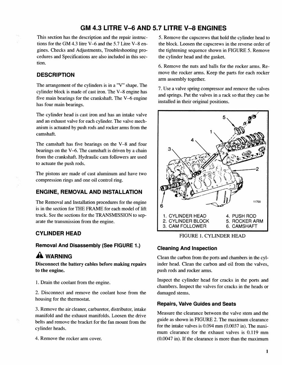
GM 4.3 LITRE V-6 AND 5.7 LITRE V-8 ENGINES This section has the description and the repair instruc¬ tions for the GM 4.3 litre V-6 and the 5.7 Litre V-8 en¬ gines. Checks and Adjustments, Troubleshooting pro¬ cedures and Specifications are also included in this sec¬ tion. DESCRIPTION The arrangement of the cylinders is in a "V" shape. The cylinder block is made of cast iron. The V-8 engine has five main bearings for the crankshaft. The V-6 engine has four main bearings. The cylinder head is cast iron and has an intake valve and an exhaust valve for each cylinder. The valve mech¬ anism is actuated by push rods and rocker arms from the camshaft. The camshaft has five bearings on the V-8 and four bearings on the V-6. The camshaft is driven by a chain from the crankshaft. Hydraulic cam followers are used to actuate the push rods. The pistons are made of cast aluminum and have two compression rings and one oil control ring. ENGINE, REMOVAL AND INSTALLATION The Removal and Installation procedures for the engine is in the section for THE FRAME for each model of lift truck. See the sections for the TRANSMISSION to sep¬ arate the transmission from the engine. CYLINDER HEAD Removal And Disassembly (See FIGURE 1.) A WARNING Disconnect the battery cables before making repairs to the engine. 1. Drain the coolant from the engine. 2. Disconnect and remove the coolant hose from the housing for the thermostat. 3. Remove the air cleaner, carburetor, distributor, intake manifold and the exhaust manifolds. Loosen the drive belts and remove the bracket for the fan mount from the cylinder heads. 4. Remove the rocker arm cover. 5. Remove the capscrews that hold the cylinder head to the block. Loosen the capscrews in the reverse order of the tightening sequence shown in FIGURE 5. Remove the cylinder head and the gasket. 6. Remove the nuts and balls for the rocker arms. Re¬ move the rocker arms. Keep the parts for each rocker arm assembly together. 7. Use a valve spring compressor and remove the valves and springs. Put the valves in a rack so that they can be installed in their original positions. 11700 6 | 1. CYLINDER HEAD 4. PUSH ROD 2. CYLINDER BLOCK 5. ROCKER ARM 3. CAM FOLLOWER 6. CAMSHAFT FIGURE 1. CYLINDER HEAD Cleaning And Inspection Clean the carbon from the ports and chambers in the cyl¬ inder head. Clean the carbon and oil from the valves, push rods and rocker arms. Inspect the cylinder head for cracks in the ports and chambers. Inspect the valves for cracks in the heads or damaged stems. Repairs, Valve Guides and Seats Measure the clearance between the valve stem and the guide as shown in FIGURE 2. The maximum clearance for the intake valves is 0.094 mm (0.0037 in). The maxi¬ mum clearance for the exhaust valves is 0.119 mm (0.0047 in). If the clearance is more than the maximum 1
Get the comprehensive service repair factory manual for the Hyster Class 5 Internal Combustion Engine Trucks - Pneumatic Tire Hyster C007 (H150H H165H H180H H200HS H200H H225H H250H H275H P150B P200B) Forklift. This electronic manual offers a distinct advantage over its paper counterpart, allowing you to zoom in on any part for clear visibility on your computer. The manual corresponds with the number of pages printed on it, making it incredibly user-friendly.
This manual covers the following models:
Hyster C007 (H150H) Forklift
Hyster C007 (H165H) Forklift
Hyster C007 (H180H) Forklift
Hyster C007 (H200HS) Forklift
Hyster C007 (H200H) Forklift
Hyster C007 (H225H) Forklift
Hyster C007 (H250H) Forklift
Hyster C007 (H275H) Forklift
Hyster C007 (P150B) Forklift
Hyster C007 (P200B) Forklift
The manual covers a wide range of components and systems, including the air compressor, brake system, cooling system, electrical schematic, engine and fuel system, transmission, steering axle, and more. It is written in a detailed, step-by-step format, making it easy for both professional mechanics and DIY enthusiasts to use. The manual is compatible with all versions of Windows and Mac, and is available in English.

 Forklift Service Repair Factory Manual DOWNLO")