CONTENTS SECTION _ SRM NUMBER THE FRAME 100 SRM 284 DC MOTOR MAINTENANCE 620 SRM 294 DRIVE AXLE, SPEED REDUCER, AND DIFFERENTIAL.. 1400 SRM 285 STEERING CONTROL UNIT 1600 SRM 257 STEERING AXLE 1600 SRM 258 THE BRAKE SYSTEM 1800 SRM 315 HYDRAULIC SYSTEM 1900 SRM 286 THE MAIN CONTROL VALVE 2000 SRM 7 7 EV-100 MOTOR CONTROLLER- DESCRIPTION AND OPERATION 2200 SRM 287 EV-100 MOTOR CONTROLLER- REPAIRS AND ADJUSTMENTS 2200 SRM 288 EV-100LX FUNCTION VALUE SETTINGS- N30AH SUPPLEMENT EV- 100/200 LX SERIES MOTOR CONTROLLER AND DIAGNOSTIC HAND SET- DESCRIPTION, CHECKS, REPAIRS, ADJUSTMENTS AND TROUBLESHOOTING 2200 SRM 460 ELECTRICAL SYSTEM... 2200 SRM 464 THE INDUSTRIAL BATTERY 2240 SRM 1 BATTERY INDICATORS 2260 SRM 138 LIFT CYLINDERS 4000 SRM 135 VISTA MAST 4000 SRM 480 LIFT CYLINDERS 4000 SRM 481 VISTA MAST REPAIR 4000 SRM 482 TRAVERSE CYLINDER AND ROTARY ACTUATOR INCH AND METRIC FASTENERS 8000 SRM 231 PERIODIC MAINTENANCE 8000 SRM 291 CAPACITIES AND SPECIFICATIONS 8000 SRM 292 DIAGRAMS 8000 SRM 293 ELECTRICAL DIAGRAMS- EV- 100/200 LX MOTOR CONTROLLER 8000 SRM 466 N30AH SERVICE MANUAL 11/93
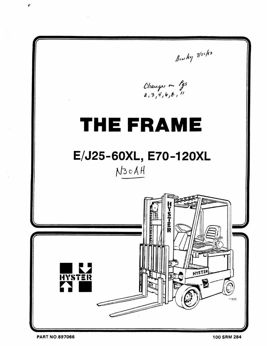
IT tÿh **ÿ» y* ,<i , " THE FRAME E/J25-60XL, E70-120XL HYS 7£l« 11523 PART NO. 897066 100 SRM284
SAFETY PRECAUTIONS MAINTENANCE AND REPAIR • When lifting parts or assemblies, make sure that all slings, chains or cables are correctly fastened and that the load being lifted is balanced. Make sure that the crane, cables and chains have the capacity to support the weight of the load. • Do not lift heavy parts by hand. Use a lifting mechanism. • Wear safety glasses. • DISCONNECT THE BATTERY CONNECTOR before doing any maintenance or repair on electric lift trucks. DISCONNECT THE BATTERY GROUND CABLE on internal combustion lift trucks. ) • Always use correct blocks to prevent the unit from rolling or falling. See "How To Put The Lift Truck On Blocks" in the OPERATING MANUAL or the PERIODIC MAINTENANCE section. • Keep the unit and working area clean and in order. i* • Use the correct tools for the job. * I • Keep the tools clean and in good condition. • Always use HYSTER APPROVED parts when making repairs. Replacement parts must meet or exceed the specifications of the original equipment manufacturer. • Make sure that all nuts, bolts, snap rings and other fastening devices are removed before using force to remove parts. • Always fasten a DO NOT OPERATE sign to the controls of the unit when making repairs or if the unit needs repairs. • Make sure you follow the DANGER, WARNING and CAUTION notes in the instructions. • Gasoline, Liquid Petroleum Gas (LPG), and Diesel are flammable fuels. Make sure that you follow the necessary safety precautions when handling these fuels and when working on these fuel systems. • Batteries generate flammable gas when they are being charged. Keep fire and sparks away from the area. Make sure the area has ventilation.
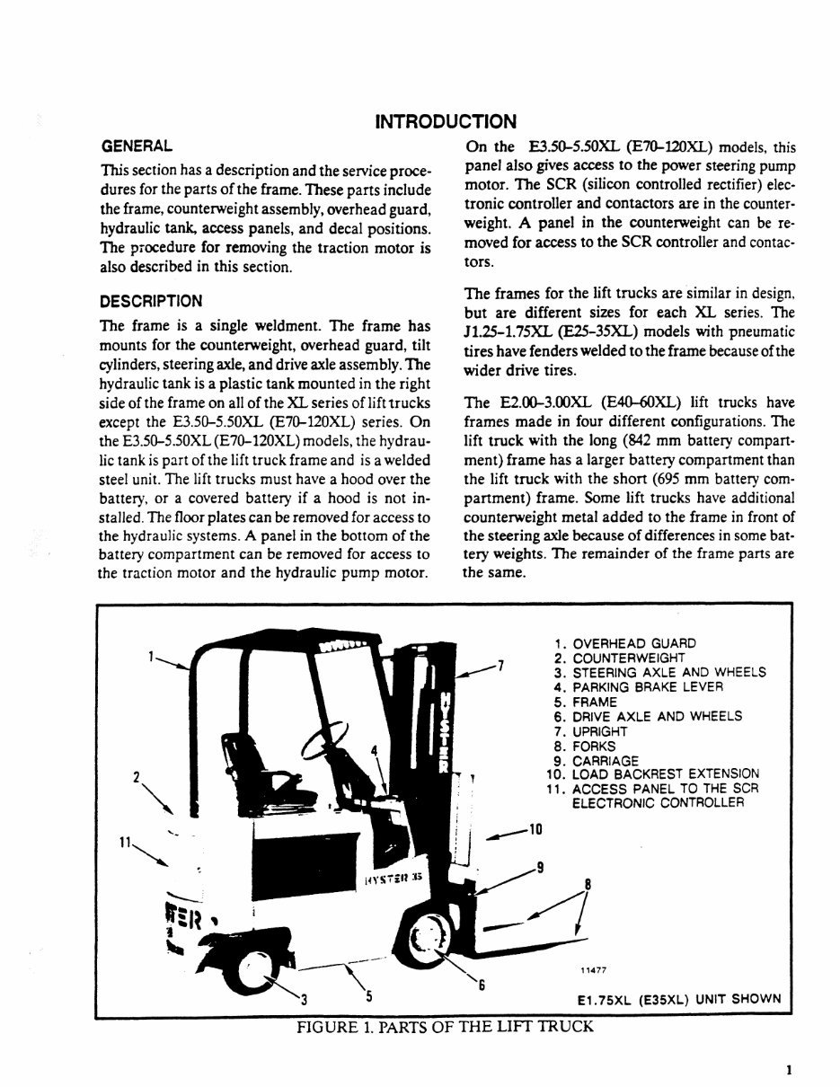
INTRODUCTION GENERAL This section has a description and the service proce¬ dures for the parts of the frame. These parts include the frame, counterweight assembly, overhead guard, hydraulic tank, access panels, and decal positions. TTie procedure for removing the traction motor is also described in this section. DESCRIPTION The frame is a single weldment. The frame has mounts for the counterweight, overhead guard, tilt cylinders, steering axle, and drive axle assembly. The hydraulic tank is a plastic tank mounted in the right side of the frame on all of the XL series of lift trucks except the E3.50-5.50XL (E70-120XL) series. On the E3.50-5.50XL (E70-120XL) models, the hydrau¬ lic tank is part of the lift truck frame and is a welded steel unit. The lift trucks must have a hood over the battery, or a covered battery if a hood is not in¬ stalled. The floor plates can be removed for access to the hydraulic systems. A panel in the bottom of the battery compartment can be removed for access to the traction motor and the hydraulic pump motor. On the E3.50-5.50XL (E70-120XL) models, this panel also gives access to the power steering pump motor. The SCR (silicon controlled rectifier) elec¬ tronic controller and contactors are in the counter¬ weight. A panel in the counterweight can be re¬ moved for access to the SCR controller and contac¬ tors. The frames for the lift trucks are similar in design, but are different sizes for each XL series. The J1.25-1.75XL (E25-35XL) models with pneumatic tires have fenders welded to the frame because of the wider drive tires. The E2.00-3.00XL (E40-60XL) lift trucks have frames made in four different configurations. The lift truck with the long (842 mm battery compart¬ ment) frame has a larger battery compartment than the lift truck with the short (695 mm battery com¬ partment) frame. Some lift trucks have additional counterweight metal added to the frame in front of the steering axle because of differences in some bat¬ tery weights. The remainder of the frame parts are the same. UYS7*W 3b n 1. OVERHEAD GUARD 2. COUNTERWEIGHT 3. STEERING AXLE AND WHEELS 4. PARKING BRAKE LEVER 5. FRAME 6. DRIVE AXLE AND WHEELS 7. UPRIGHT 8. FORKS 9. CARRIAGE LOAD BACKREST EXTENSION ACCESS PANEL TO THE SCR ELECTRONIC CONTROLLER 11477 E1.75XL (E35XL) UNIT SHOWN FIGURE 1. PARTS OF THE LIFT TRUCK 1
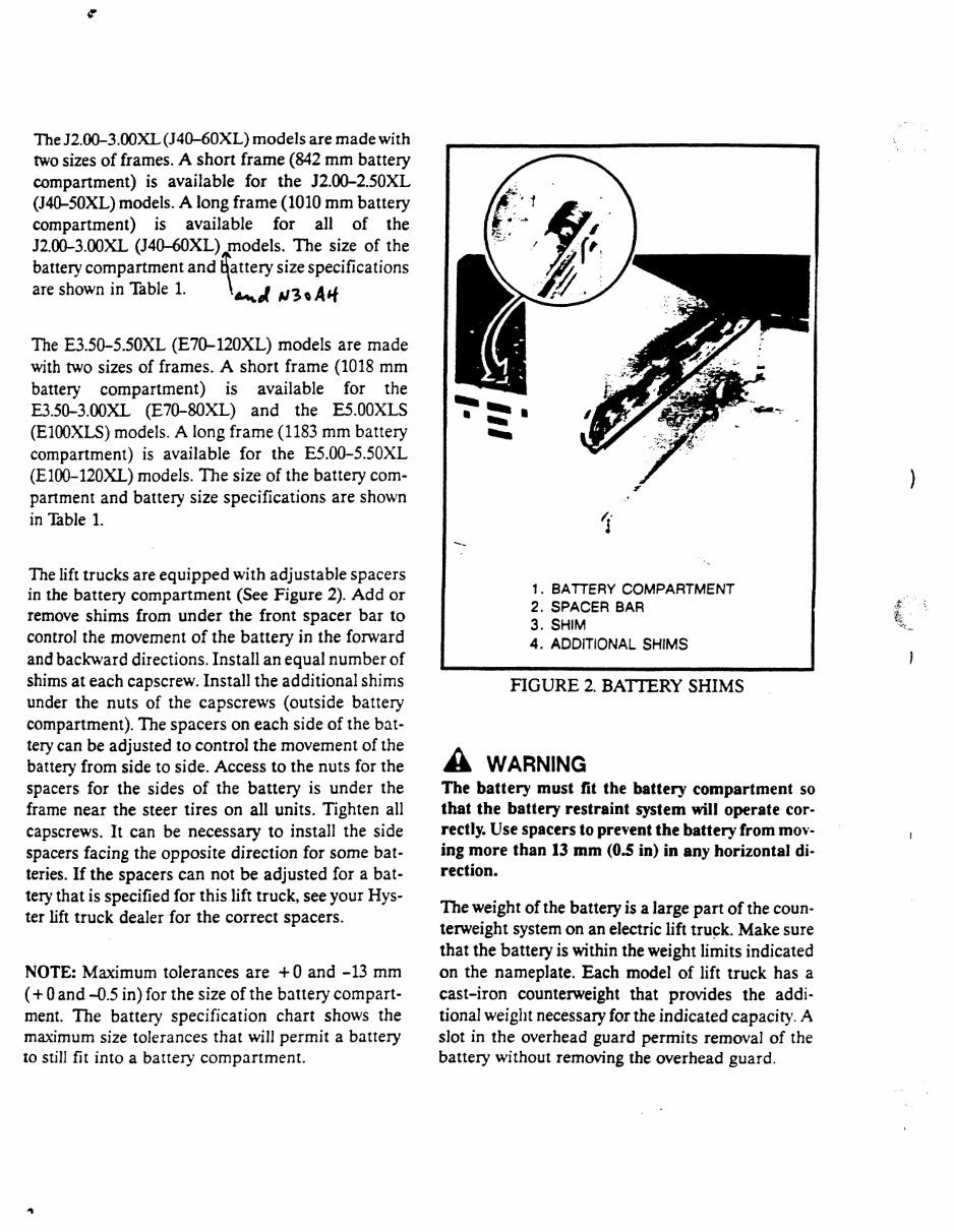
<r The J2.00-3.00XL (J40-60XL) models are made with two sizes of frames. A short frame (842 mm battery compartment) is available for the J2.00-2.50XL (J40-50XL) models. A long frame (1010 mm battery compartment) is available for all of the J2.00-3.00XL (J40-60XL) models. The size of the battery compartment and battery size specifications are shown in Table 1. The E3.50-5.50XL (E70-120XL) models are made with two sizes of frames. A short frame (1018 mm battery compartment) is available for the E3.50-3.00XL (E70-80XL) and the E5.00XLS (E100XLS) models. A long frame (1183 mm battery compartment) is available for the E5.00-5.50XL (E100-120XL) models. The size of the battery com¬ partment and battery size specifications are shown in Table 1. The lift trucks are equipped with adjustable spacers in the battery compartment (See Figure 2). Add or remove shims from under the front spacer bar to control the movement of the battery in the forward and backward directions. Install an equal number of shims at each capscrew. Install the additional shims under the nuts of the capscrews (outside battery compartment). The spacers on each side of the bat¬ tery can be adjusted to control the movement of the battery from side to side. Access to the nuts for the spacers for the sides of the battery is under the frame near the steer tires on all units. Tighten all capscrews. It can be necessary to install the side spacers facing the opposite direction for some bat¬ teries. If the spacers can not be adjusted for a bat¬ tery that is specified for this lift truck, see your Hys- ter lift truck dealer for the correct spacers. NOTE: Maximum tolerances are + 0 and -13 mm ( + 0 and -0.5 in) for the size of the battery compart¬ ment. The battery specification chart shows the maximum size tolerances that will permit a battery to still fit into a battery compartment. 1. BATTERY COMPARTMENT 2. SPACER BAR 3. SHIM 4. ADDITIONAL SHIMS FIGURE 2. BATTERY SHIMS A WARNING The battery must fit the battery compartment so that the battery restraint system will operate cor¬ rectly. Use spacers to prevent the battery from mov¬ ing more than 13 mm (0.5 in) in any horizontal di¬ rection. The weight of the battery is a large part of the coun¬ terweight system on an electric lift truck. Make sure that the battery is within the weight limits indicated on the nameplate. Each model of lift truck has a cast-iron counterweight that provides the addi¬ tional weight necessary for the indicated capacity. A slot in the overhead guard permits removal of the battery without removing the overhead guard.
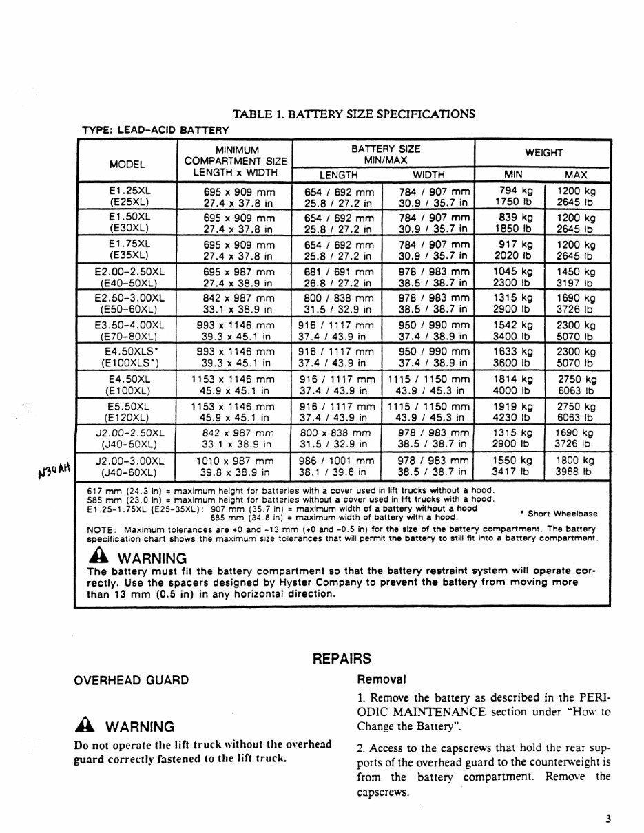
TABLE 1. BATTERY SIZE SPECIFICATIONS TYPE: LEAD-ACID BATTERY MODEL MINIMUM COMPARTMENT SIZE LENGTH x WIDTH BATTERY SIZE MIN/MAX WEIGHT LENGTH WIDTH MIN MAX E1.25XL (E25XL) 695 x 909 mm 27.4 x 37.8 in 654 / 692 mm 25.8 / 27.2 in 784 / 907 mm 30.9 / 35.7 in 794 kg 1750 lb 1200 kg 2645 lb E1.50XL (E30XL) 695 x 909 mm 27.4 x 37.8 in 654 / 692 mm 25.8 1 27.2 in 784 / 907 mm 30.9 / 35.7 in 839 kg 1850 lb 1200 kg 2645 lb E1.75XL (E35XL) 695 x 909 mm 27.4 x 37.8 in 654 / 692 mm 25.8 / 27.2 in 784 / 907 mm 30.9 / 35.7 in 917 kg 2020 lb 1200 kg 2645 lb E2.00-2.50XL (E40-50XL) 695 x 987 mm 27.4 x 38.9 in 681 / 691 mm 26.8 / 27.2 in 978 / 983 mm 38.5 / 38.7 in 1045 kg 2300 lb 1450 kg 3197 lb E2.50-3.00XL (E50-60XL) 842 x 987 mm 33.1 x 38.9 in 800 / 838 mm 31.5 / 32.9 in 978 / 983 mm 38.5 / 38.7 in 1315 kg 2900 lb 1690 kg 3726 lb E3.50-4.00XL (E70-80XL) 993 x 1146 mm 39.3 x 45.1 in 916 / 1117 mm 37.4 / 43.9 in 950 / 990 mm 37.4 / 38.9 in 1542 kg 3400 lb 2300 kg 5070 lb E4.50XLS" (E100XLS") 993 x 1146 mm 39.3 x 45.1 in 916 / 1117 mm 37.4 / 43.9 in 950 / 990 mm 37.4 / 38.9 in 1633 kg 3600 lb 2300 kg 5070 lb E4.50XL (E100XL) 1153 x 1146 mm 45.9 x 45.1 in 916 / 1117 mm 37.4 / 43.9 in 1115 / 1150 mm 43.9 / 45.3 in 1814 kg 4000 lb 2750 kg 6063 lb E5.50XL (E120XL) 1153 x 1146 mm 45.9 x 45. 1 in 916 / 1117 mm 37.4 / 43.9 in 1115 / 1150 mm 43.9 / 45.3 in 1919 kg 4230 lb 2750 kg 6063 lb J2.00-2.50XL (J40-50XL) 842 x 987 mm 33.1 x 38.9 in 800 x 838 mm 31.5 / 32.9 in 978 / 983 mm 38.5 / 38.7 in 1315 kg 2900 lb 1690 kg 3726 lb J2.00-3.00XL (J40-60XL) 1010 x 987 mm 39.8 x 38.9 in 986 / 1001 mm 38.1 / 39.6 in 978 / 983 mm 38.5 / 38.7 in 1550 kg 3417 lb 1800 kg 3968 lb 617 mm (24.3 in) = maximum height for batteries with a cover used In lift trucks without a hood. 585 mm (23.0 In) = maximum height for batteries without a cover used In lift trucks with a hood. E1 .25-1.75XL (E25-35XL) : 907 mm (35.7 in) = maximum width of a battery without a hood . _ 885 mm (34.8 in) = maximum width of battery with a hood. snort wneeioase NOTE: Maximum tolerances are +0 and -13 mm (+0 and -0.5 in) for the size of the battery compartment. The battery specification chart shows the maximum size tolerances that will permit the battery to still fit into a battery compartment. A WARNING The battery must fit the battery compartment so that the battery restraint system will operate cor¬ rectly. Use the spacers designed by Hyster Company to prevent the battery from moving more than 13 mm (0.5 in) in any horizontal direction. REPAIRS OVERHEAD GUARD Removal A WARNING Do not operate the lift truck without the overhead guard correctly fastened to the lift truck. 1. Remove the battery as described in the PERI¬ ODIC MAINTENANCE section under "How to Change the Battery". 2. Access to the capscrews that hold the rear sup¬ ports of the overhead guard to the counterweight is from the battery compartment. Remove the capscrews. 3
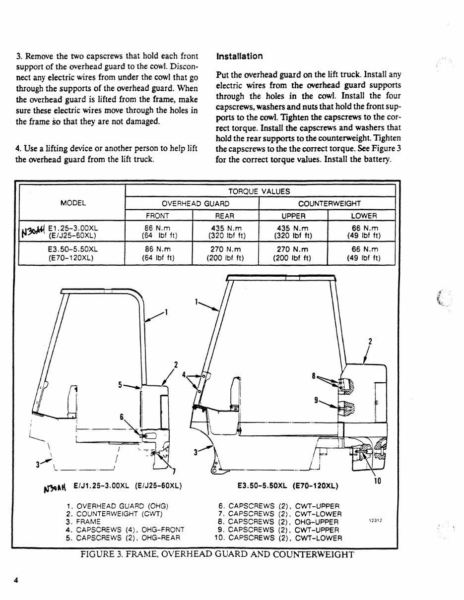
3. Remove the two capscrews that hold each front support of the overhead guard to the cowl. Discon¬ nect any electric wires from under the cowl that go through the supports of the overhead guard. When the overhead guard is lifted from the frame, make sure these electric wires move through the holes in the frame so that they are not damaged. 4. Use a lifting device or another person to help lift the overhead guard from the lift truck. Installation Put the overhead guard on the lift truck. Install any electric wires from the overhead guard supports through the holes in the cowl. Install the four capscrews, washers and nuts that hold the front sup¬ ports to the cowl. Tighten the capscrews to the cor¬ rect torque. Install the capscrews and washers that hold the rear supports to the counterweight. Tighten the capscrews to the the correct torque. See Figure 3 for the correct torque values. Install the battery. MODEL TORQUE VALUES OVERHEAD GUARD COUNTERWEIGHT FRONT REAR UPPER LOWER iffcvWl E1.25-3.00XL P** (E/J25-60XL) 86 N.m (64 ibf ft) 435 N.m (320 Ibf ft) 435 N.m (320 Ibf ft) 66 N.m (49 Ibf ft) E3.50-5.50XL (E70-120XL) 86 N.m (64 Ibf ft) 270 N.m (200 Ibf ft) 270 N.m (200 Ibf ft) 66 N.m (49 Ibf ft) E/J1.25-3.00XL (E/J25-60XL) 1. OVERHEAD GUARD (OHG) 2. COUNTERWEIGHT (CWT) 3. FRAME 4. CAPSCREWS (4). OHG-FRONT 5. CAPSCREWS (2), OHG-REAR E3.50-5.50XL (E70-120XL) 6. CAPSCREWS (2). CWT-UPPER 7. CAPSCREWS (2), CWT-LOWER 8. CAPSCREWS (2). OHG-UPPER 9. CAPSCREWS (2), CWT-UPPER 10. CAPSCREWS (2), CWT-LOWER FIGURE 3. FRAME, OVERHEAD GUARD AND COUNTERWEIGHT 4
You're Reading a Preview
What's Included?
Lifetime Access
Fast Download Speeds
Online & Offline Access
Access PDF Contents & Bookmarks
Full Search Facility
Print one or all pages of your manual
$41.99
Hyster B210 (N30AH) Forklift Service Repair Manual
Hyster B210 (N30AH) Forklift Service Repair Factory Manual is an electronic version of a comprehensive manual used by dealer technicians and mechanics for diagnosing and repairing vehicles. This Professional Quality Service Repair Workshop Manual provides highly detailed information, making it a valuable resource for both professional mechanics and DIY enthusiasts. It is 100% complete and intact, with no missing or corrupt pages or sections.
The manual covers a wide range of topics including battery indicators, brake system, DC motor maintenance, diagrams, differential, electrical checks and adjustments, electrical diagrams, EV-100 motor controller description and operation, frame, gauges, large batteries, lift cylinders, main control valve and auxiliary solenoid valve used in the hydraulic system, maintenance schedule, mast repair, metric and inch (SAE) fasteners, schematic and diagram, steering axle, steering control unit, steering system, tilt cylinders, two-stage and three-stage uprights, upright, and more.
It comes in PDF format and is compatible with all versions of Windows and Mac operating systems. The language of the manual is English, and it requires Adobe Reader and WinZip for access.
Models Covered: Hyster B210 (N30AH) Forklift
Reviews
Q&A
Recently Viewed
5,521,897Happy Clients
2,594,462eManuals
1,120,453Trusted Sellers
15Years in Business
Price:
Actual Price:
Hyster B210 (N30AH) Forklift Service Repair Manual

 Forklift Service Repair Manual")