1 Important Safety Information Most accidents involving product operation, maintenance and repair are caused by failure to observe basic safety rules or precautions. An accident can often be avoided by recognizing potentially hazardous situations before an accident occurs. A person must be alert to potential hazards. This person should also have the necessary training, skills and tools to perform these functions properly. Read and understand all safety precautions and warnings before operating or performing lubrication, maintenance and repair on this product. Basic safety precautions are listed in the “Safety” section of the Service or Technical Manual. Additional safety precautions are listed in the “Safety” section of the owner/operation/maintenance publication. Specific safety warnings for all these publications are provided in the description of operations where hazards exist. WARNING labels have also been put on the product to provide instructions and to identify specific hazards. If these hazard warnings are not heeded, bodily injury or death could occur to you or other persons. Warnings in this publication and on the product labels are identified by the following symbol. WARNING Improper operation, lubrication, maintenance or repair of this product can be dangerous and could result in injury or death. Do not operate or perform any lubrication, maintenance or repair on this product, until you have read and understood the operation, lubrication, maintenance and repair information. Operations that may cause product damage are identified by NOTICE labels on the product and in this publication. DAEWOO cannot anticipate every possible circumstance that might involve a potential hazard. The warnings in this publication and on the product are therefore not all inclusive. If a tool, procedure, work method or operating technique not specifically recommended by DAEWOO is used, you must satisfy yourself that it is safe for you and others. You should also ensure that the product will not be damaged or made unsafe by the operation, lubrication, maintenance or repair procedures you choose. The information, specifications, and illustrations in this publication are on the basis of information available at the time it was written. The specifications, torques, pressures, measurements, adjustments, illustrations, and other items can change at any time. These changes can affect the service given to the product. Obtain the complete and most current information before starting any job. DAEWOO dealers have the most current information available.
G420E/G424E Tier LP Engine Table of Contents 3 WARNING Read this entire manual and all other publications pertaining to the work to be performed before installing, operating, or servicing this equipment. Practice all plant and safety instructions and precautions. Failure to follow instructions can cause personal injury and/or property damage. The engine or other type of prime mover should be equipped with an over speed (over temperature, or overpressure, where applicable) shutdown device(s), that operates totally independently of the prime mover control device(s) to protect against runaway or damage to the engine or other type of prime mover with possible personal injury or loss of life should the mechanical-hydraulic governor(s) or electric control(s), the actuator(s), fuel control(s), the driving mechanism(s), the linkage(s), or the controlled device(s) fail. CAUTION To prevent damage to a control system that uses an alternator or battery-charging device, make sure the charging device is turned off before disconnecting the battery from the system. Electronic controls contain static-sensitive parts. Observe the following precautions to prevent damage to these parts. Discharge body static before handling the control (with power to the control turned off, contact a grounded surface and maintain contact while handling the control). Avoid all plastic, vinyl, and Styrofoam (except antistatic versions) around printed circuit boards. Do not touch the components or conductors on a printed circuit board with your hands or with conductive devices. IMPORTANT DEFINITIONS WARNING—indicates a potentially hazardous situation, which, if not avoided, could result in death or serious injury. CAUTION—indicates a potentially hazardous situation, which, if not avoided, could result in damage to equipment. NOTE—provides other helpful information that does not fall under the warning or caution categories. * This manual shows just LP fuel and engine control system for TIER- LP engine, so regarding other ares(basic engine), please refer to the separate manual of SB4008E for G420 and SB2215E for G424.
G420E/G424E Tier LP Engine Table of Contents 5 Index WORKING WITH LPG EQUIPMENT CHAPTER 0 LPG AND LPG FUEL TANKS LPG Fuel Supply ........................................................ 8 LPG Fuel Tanks.......................................................... 9 Installing LPG Fuel Tanks .......................................... 9 LPG Fuel Tank Components .................................... 10 Fuel Gauge .............................................................. 10 Service Valve ........................................................... 10 Quick Disconnect Coupling ...................................... 11 Filler Valve................................................................ 11 CHAPTER 1 ENGINE SPECIFICATION Indication of Engine Serial Number ......................... 12 Specifications(G420E) ............................................. 13 Specifications(G424E) ............................................. 14 CHAPTER 2 MI-04 LPG SYSTEM OPERATIONAL OVERVIEW MI-04 General Description ....................................... 15 MI-04 LP Fuel Filter.................................................. 17 MI-04 Fuel Lock-Off (Electric) .................................. 17 MI-04 N-2001 Regulator/Converter.......................... 18 N-2001 Theory of Operation .................................... 19 MI-04 N-CA55-500TR Mixer .................................... 20 N-CA55-500-TR Air/Fuel Mixer Theory of Operation ................................................................. 20 MI-04 Electronic Throttle .......................................... 22 MI-04 Fuel Trim Valve .............................................. 23 Heated Exhaust Gas Oxygen Sensor (HEGO) ........ 24 MI-04 SECM (General Description) ......................... 25 MI-04 SECM (Fuel Management) ............................ 25 MI-04 SECM (Load/Speed Management) ................ 27 MI-04 Ignition management ..................................... 29 CHAPTER 3 MI- 04 MAINTENANCE SCHEDULE RECOMMENDED MAINTENANCE SCHEDULE.....30 Test Fuel System for Leaks ......................................30 Inspect Engine for Fluid Leaks .................................30 Inspect Vacuum Lines and Fittings...........................30 Inspect Electrical System .........................................30 Inspect Acceleration Pedal Operation ......................31 Check Coolant Level ................................................31 Inspect Coolant Hoses .............................................31 Inspect Battery System ............................................31 Inspect Ignition System ............................................31 Replace Spark Plugs ................................................31 Replace LP Fuel Filter Element ................................32 Testing Fuel Lock-off Operation ...............................33 Pressure Regulator/Converter Testing and nspection ..................................................................33 Fuel Trim Valve Inspection (FTV) .............................33 Inspect Air/Fuel Valve Mixer Assembly.....................33 Inspect for Intake Leaks ...........................................34 Inspect Throttle Assembly ........................................34 Checking the TMAP Sensor .....................................34 Inspect Engine for Exhaust Leaks ............................34 Replace Oxygen Sensor ..........................................34 Maintenance Schedule .............................................35 CHAPTER 4 MI-04 LP BASIC TROUBLESHOOTING Basic Troubleshooting ..............................................37 CHAPTER 5 MI-04 LP ADVANCED DIAGNOSTICS Advanced Diagnostics ..............................................44 Reading Diagnostic Fault Codes ..............................44 Displaying Fault Codes (DFC) From SECM Memory ....................................................................45 Clearing Fault (DFC) Codes .....................................45 Fault Action Descriptions ..........................................45 Fault List Definitions .................................................46 Table a. MI-04 Diagnostic Fault Codes (Flash Codes) ......................................................................48 CHAPTER 6 MI-04 ELECTRICAL CONNECTIONS Resistance Checks...................................................62 Voltage Checks ........................................................63
G420E/G424E Tier LP Engine Table of Contents 6 CHAPTER 7 N2001 PRESSURE REGULATOR /CONVERTER Removal and Installation of N2001 LP Regulator/Converter................................................. 64 Hose Connections.................................................... 65 N2001 Removal Steps: ............................................ 66 N2001 Regulator Disassembly Steps: ..................... 67 N2001 Disassembled Service .................................. 69 CHAPTER 8 N-CA55-500TR AIR/FUEL MIXER Removal and Installation of the N-CA55-500TR Mixer ........................................................................ 70 N-CA55-500TR Mixer Removal Steps: .................... 71 N-CA55-500TR Disassembly and Service ............... 72 N-CA55-500TR Disassembled Service.................... 74 Installing the Mixer/Throttle Assembly ..................... 75 CHAPTER 9 TEST AND ADJUSTMENTS N2001 Service Testing ............................................. 78 Primary Stage Test Hardware .................................. 79 Primary Stage Pressure Test.................................... 79 N-CA55-500TR Service AVV (Air Valve Vacuum) Testing...................................................................... 81 Ignition Timing Adjustment ....................................... 82 Idle Mixture Adjustment ............................................ 85 CHAPTER 10 SERVICE TOOL KIT Service Tool Kit ........................................................ 87
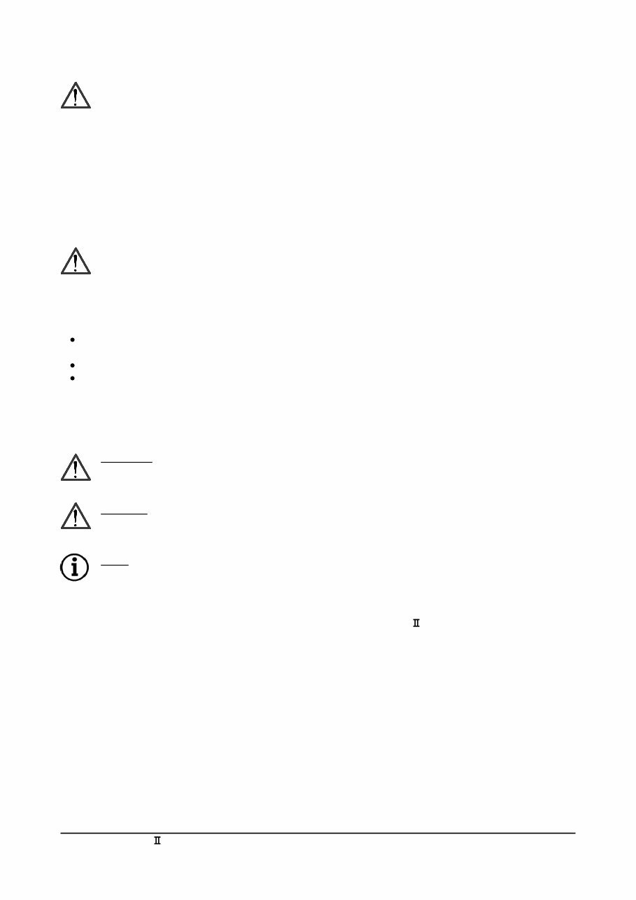
G420E/G424E Tier LP Engine Working with LPG Equipment 7 WORKING WITH LPG EQUIPMENT WARNING Propane Vapor is heavier than air and can collect in low areas when adequate ventilation or air movement is not present to disperse it. Never check for leaks with a flame or match. Use a leak detector solution or an electronic detector. Make sure the container service valve is closed when connecting or disconnecting. If the container service valve does not operate properly, discontinue use and contact your propane supplier. Never insert any object into the pressure relief valve. WARNING LP gas is highly flammable. To prevent personal injury, keep fire and flammable materials away from the lift truck when work is done on the fuel system. Gas vapor may reduce oxygen available for breathing, cause headache, nausea, dizziness and unconsciousness and lead to injury or death. Always operate the forklift in a well ventilated area Liquid propane may cause freezing of tissue or frostbite. Avoid direct contact with skin or tissue; always wear appropriate safety protection including gloves and safety glasses when working with liquid propane. CAUTION The regulator/converter and mixer are part of a certified system complying with EPA and CARB 2004 requirements. Only trained certified technicians should perform disassemble, service or replacement of the regulator/converter or mixer. CAUTION LPG fueled machinery may be garaged anywhere gasoline powered vehicles are garaged. When machines are stored for a long period, it is advisable to shut off the tank supply valve and run the machine until the fuel trapped down stream of the valve is depleted. NOTE NFPA (National Fire Protection Agency) 58 covers the procedures for storage and garaging for repair purposes, on propane powered equipment. CAUTION Safety is an important consideration for any repair facility, and repairing LPG fueled machinery is no exception. Refer to the NFPA (National Fire Protection Agency) for the appropriate fire extinguisher specifications and fluorescent lighting requirements. Propane has a heavier than air vapor density and will fall if a leak occurs, while natural gas, by comparison, will rise in the event of a leak (Figure 1). This is an important property that technicians need to be aware of when performing maintenance. When repairing propane machinery, the work should be performed in the lowest point of the facility where possible. The tank supply should be shut off, except when required for running equipment. Diesel CNG LPG Figure 1
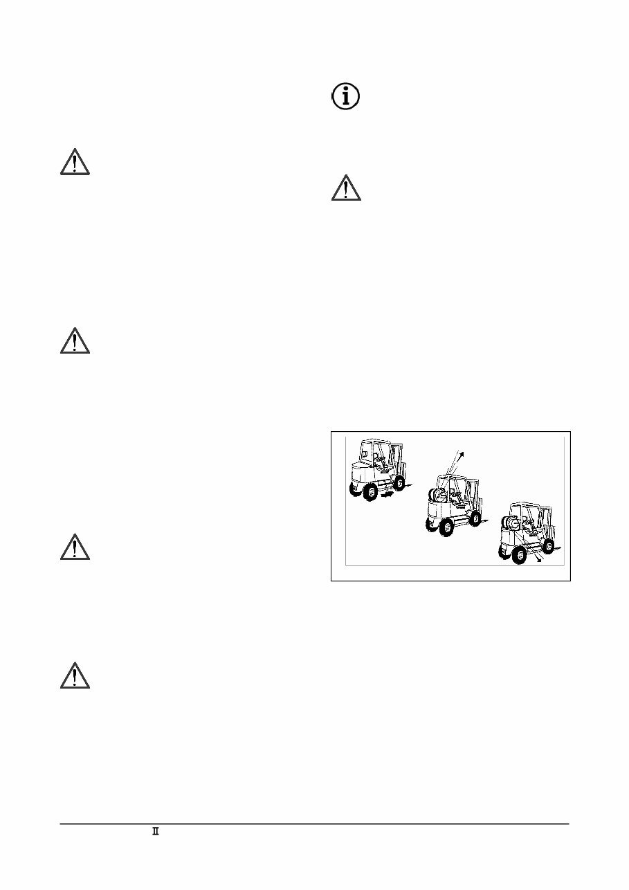
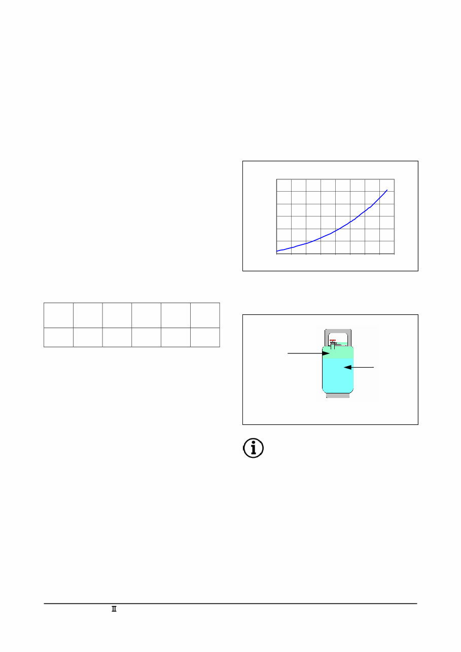
G420E/G424E Tier LP Engine LPG and LPG Fuel Tanks 8 CHAPTER 0 LPG AND LPG FUEL TANKS LPG Fuel Supply Liquefied petroleum gas (LPG) consists mainly of propane, propylene, butane, and butylenes in various mixtures. LPG is produced as a by-product of natural gas processing or it can be obtained from crude oil as part of the oil refining process. LPG, like gasoline, is a compound of hydrogen and carbon, commonly called hydrocarbons. In its natural state, propane is colorless and odorless; an odorant (ethyl mercaptan) is added to the fuel so its presence can be detected. There are currently three grades of propane available in the United States. A propane grade designation of HD5 (not exceeding 5% propylene), is used for internal combustion engines while much higher levels of propylene (HD10) are used as commercial grade propane along with a commercial propane /butane mixture. APPROXIMATE COMPOSITION OF HD5 PROPANE BY VOLUME Propane (C3H8) Propy lene Butane (C4H10) Iso- Butane Methane (CH4) TOTAL 90.0% min. 5% max. 2.0% 1.5% 1.5% 100% An advantage of LPG is the ability to safely store and transport the product in the liquid state. In the liquid state propane is approximately 270 times as dense as it is in a gaseous form. By pressurizing a container of LPG we can effectively raise the boiling point above –44 deg. C / -42 deg. C, keeping the propane in liquid form. The point at which the liquid becomes a gas (boiling point) depends on the amount of pressure applied to the container. This process operates similarly to an engine coolant system where water is kept from boiling by pressurizing the system and adding a mixture of glycol. For example water at normal atmospheric pressure will boil at 212 deg. F / 100 deg. C. If an engines operating temperature is approximately 230 deg. F / 110 deg. C, then the water in an open un- pressurized cooling system would simply boil off into steam, eventually leaving the cooling system empty and over heating the engine. If we install a 10 PSIG cap on the radiator, pressurizing the cooling system to 10 PSIG, the boiling point of the water increases to 242 deg. F / 117 deg. C, which will cause the water to remain in liquid state at the engines operating temperature. The same principle is applied to LPG in a container, commonly referred to as an LPG tank or cylinder. Typically an LPG tank is not filled over 80% capacity allowing for a 20% vapor expansion space. Outside air temperature effect’s an LPG tank and must be considered when using an LPG system. (Figure 2) shows the relationship between pressure and temperature in a LPG tank at a steady state condition. With 128 PSIG vapor pressure acting against the liquid propane the boiling point has been raised to slightly more than 80 deg. F / 27 deg. C. NOTE Vapor pressure inside an LPG tank depends on the ambient air temperature outside the tank, not the amount of liquid inside the tank. A tank that is ¾ full of liquid propane at 80 deg. F will contain the same vapor pressure as a tank that is only ¼ full of liquid propane. LPG’s relative ease of vaporization makes it an excellent fuel for low-rpm engines on start-and-stop operations. The more readily a fuel vaporizes the more complete combustion will be. Because propane has a low boiling point (-44F), and is a low carbon fuel, engine life can be extended due to less cylinder wall wash down and little, if any, carbon build up. 0 50 100 150 200 250 300 -20 0 20 40 60 80 100 120 140 Temperature, deg F Pressure, psig LPG Tank Pressure VS Temperature Compressed Vapor 128 PSIG Liquid Propane LPG Tank Figure 2 Figure 3
You're Reading a Preview
What's Included?
Lifetime Access
Fast Download Speeds
Online & Offline Access
Access PDF Contents & Bookmarks
Full Search Facility
Print one or all pages of your manual
$71.99
Doosan G/GC Series Forklift Service & Repair Manual
Doosan G/GC Series Forklift Service & Repair Manual
Engines covered:
G420E Tier II LP Engine
G424E Tier II LP Engine
Models covered:
G420E Tier II LP Engine
G15S-2
G18S-2
G20SC-2
GC15S-2
GC18S-2
GC20SC-2
G424E Tier II LP Engine
G20E-3
G25E-3
G30E-3
G32E-3
GC20E-3
GC25E-3
GC30E-3
GC32E-3
This technical manual contains service, maintenance, troubleshooting, and replacement procedures for your forklift, including step-by-step instructions, clear images, and exploded-view illustrations.
It provides comprehensive diagrams, detailed illustrations, and all the manufacturer's specifications and technical information you might need.
Whether you are a professional mechanic or a DIY enthusiast, this manual enables you to safely and efficiently service and repair your forklift.
No matter if you are in the shop or at a jobsite, as long as you have a smartphone or laptop, you'll have your repair manual with you. Simply pull out the repair manual, fix whatever is broken, and keep downtimes to a minimum!
Printable: Yes Language: English Compatibility: Pretty much any electronic device, incl. PC & Mac computers, Android and Apple smartphones & tablet, etc. Requirements: Adobe Reader (free)
Reviews
Q&A
Recently Viewed
5,521,897Happy Clients
2,594,462eManuals
1,120,453Trusted Sellers
15Years in Business
Price:
Actual Price:
Doosan G/GC Series Forklift Service & Repair Manual