



For use in service manual
form SB4249E
SB4250E03
Jan. 2008
SERVICE MANUAL CONTENTS
NOTICE
This form lists the contents of the complete Service Manual for this product.
The items listed with form numbers are available and included in this manual.
If form numbers are listed with mark(*), they are not available for the initial
release of the manual. When items are updated, or supplements are added,
they will be provided separately.
TITLE BINDER# FORM NUMBER
Service Manual Contents 1/2, 2/2 SB4250E03
Safety 1/2, 2/2 SB2003E00
Torque Specifications 1/2, 2/2 SB2004E00
ENGINE
B3.3 Diesel Engine 1/2 SB4310E00
G420F(FE) LP/Gasoline Engine 1/2 SB4241E00
G424F(FE) LP/Dual Fuel Engine 1/2 SB4251E00
Delco Remy CS-121 Series Alternator 1/2 SB2007E02
Bosch K1 Series Alternator 1/2 SB2008E01
4TNV98 & 4TNE98 Diesel Engine 2/2 SB4319E00
POWER TRAIN
Power Train 2/2 SB4253E02
Power Train D & A 2/2 SB4254E00
VEHICLE SYSTEM
Vehicle System 2/2 SB4255E01
Vehicle System D & A 2/2 SB4256E01
Hydraulic Schematic 2/2 SB4257E01
Electric Schematic 2/2 SB4258E02
OPERATION & MAINTENANCE
Operation & Maintenance Manual 2/2 SB2349E00
Models ; D20/25/30S-5, D33S-5, D35C-5, G20/25/30E-5, G20/25/30P-5
GC20/25/30/33E-5, GC20/25/30/33P-5, G33P-5, G35C-5

SB2003E00
Dec. 1998
The proper and safe lubrication and maintenance
for this machine, recommended by DOOSAN, are
outlined in the OPERATION & MAINTENANCE
GUIDE for this machine.
Improper performance of lubrication or
maintenance procedures is dangerous and could
result in injury or death. Read and understand the
OPERATION & MAINTENANCE GUIDE before
performing any lubrication or maintenance.
Do not operate this machine unless you have
read and understand the instructions in the
OPERATOR'S GUIDE. Improper machine
operation is dangerous and could result in
injury or death.
5. Use steps and grab handles (if applicable) when
mounting or dismounting a machine. Clean any mud or
debris from steps, walkways or work platforms before
using. Always face machine when using steps, ladders
and walkways. When it is not possible to use the
designed access system, provide ladders, scaffolds, or
work platforms to perform safe repair operations.
6. To avoid back injury, use a hoist when lifting
components which weigh 23 kg (50 lb.) or more. Make
sure all chains, hooks, slings, etc., are in good
condition and are of the correct capacity. Be sure
hooks are positioned correctly. Lifting eyes are not to
be side loaded during a lifting operation.
7. To avoid burns, be alert for hot parts on machines
which have just been stopped and hot fluids in lines,
tubes and compartments.
8. Be careful when removing cover plates. Gradually
back off the last two bolts or nuts located at opposite
ends of the cover or device and pry cover loose to
relieve any spring or other pressure, before removing
the last two bolts or nuts completely.
9. Be careful when removing filler caps, breathers and
plugs on the machine. Hold a rag over the cap or plug
to prevent being sprayed or splashed by liquids under
pressure. The danger is even greater if the machine
has just been stopped because fluids can be hot.
10. Always use tools that are in good condition and be
sure you understand how to use them before
performing any service work.
11. Reinstall all fasteners with same part number. Do not
use a lesser quality fastener if replacements are
necessary. Do not mix metric fasteners with
standard nuts and bolts.
12. If possible, make all repairs with the machine parked
on a level, hard surface. Block machine so it does
not roll while working on or under machine.
Theserviceman or mechanic maybe unfamiliar with many
of the systems on this machine. This makes it important
to use caution when performing service work. A
knowledge of the system and/or components is
important before the removal or disassembly of any
component.
Because of the size of some of the machine
components, the serviceman or mechanic should check
the weights noted in this Manual, Use proper lifting
procedures when removing any components.
Following is a list of basic precautions that should always
be observed.
1. Readand understand all Warning plates and decals on
the machine before operating, lubricating or repairing
the product.
2. Always wear protective glasses and protective shoes
when working around machines. In particular, wear
protective glasses when pounding on any part of the
machine or its attachments with a hammer or sledge.
Use welders gloves, hood/goggles, apron and other
protective clothing appropriate to the welding job
being performed. Do not wear loose-fitting or torn
clothing. Remove all rings from fingers when working
on machinery.
3. Do not work on any machine that is supported only by
lift jacks or a hoist. Always use blocks or jack stands
to support the machine before performing any
disassembly.
4. Lower the forks or other implements to the ground
before performing any work on the machine. If this
cannot be done, make sure the forks or other
implements are blocked correctly to prevent them
from dropping unexpectedly.
SAFETY
WARNING
WARNING WARNING
1 of 2

21. Do not operate a machine if any rotating part is
damaged or contacts any other part during
operation. Any high speed rotating component that
has been damaged or altered should be checked
for balance before reusing.
22. On LP equipped lift trucks, be sure to close the
valve on the LP tank before service work is
performed. Always close the valve on the LP tank
when the lift truck is being stored. Do not check for
LP leaks with an open flame.
23. Caution should be used to avoid breathing dust that
may be generated when handling components
containing asbestos fibers. If this dust is inhaled, it
can be hazardous to your health. Components in
DOOSAN products that may contain asbestos
fibers are brake pads, brake band and lining
assemblies, clutch plates and some gaskets. The
asbestos used in these components is usually
bound in a resin or sealed in some way. Normal
handling is not hazardous as long as airborne dust
which contains asbestos is not generated.
If dust which may contain asbestos is present, there are
several common sense guidelines that should be
followed.
a. Never use compressed air for cleaning.
b. Avoid brushing or grinding of asbestos containing
materials.
c. For clean up, use wet methods or a vacuum
equipped with a high efficiency particulate air
(HEPA) filter.
d. Use exhaust ventilation on permanent machining
jobs.
e. Wear an approved respirator if there is no other
way to control the dust.
f. Comply with applicable rules and regulations for the
work place (for example in the U.S.A., OSHA
requirements as set forth in 29 CFR 1910. 1001).
g. Follow environmental rules and regulations for
disposal of asbestos.
h. Avoid areas where asbestos particles may be in the
air.
13. Disconnect battery and discharge any capacitors
(electric trucks) before starting to work on machine.
Hang "Do Not Operate" tag in the Operator's
Compartment.
14. Repairs, which require welding, should be
performed only with the benefit of the appropriate
reference information and by personnel adequately
trained and knowledgeable in welding procedures.
Determine type of metal being welded and select
correct welding procedure and electrodes, rods or
wire to provide a weld metal strength equivalent at
least to that of parent metal.
15. Do not damage wiring during removal operations.
Reinstall the wiring so it is not damaged nor will it
be damaged in operation by contacting sharp
corners, or by rubbing against some object or hot
surface. Do not connect wiring to a line containing
fluid.
16. Be sure all protective devices including guards and
shields are properly installed and functioning
correctly before starting a repair. If a guard or shield
must be removed to perform the repair work, use
extra caution.
17. Always support the mast and carriage to keep
carriage or attachments raised when maintenance
or repair work is performed, which requires the
mast in the raised position.
18. Loose or damaged fuel, lubricant and hydraulic
lines, tubes and hoses can cause fires. Do not
bend or strike high pressure lines or install ones
which have been bent or damaged. Inspect lines,
tubes and hoses carefully. Do not check for leaks
with your hands. Pin hole (very small) leaks can
result in a high velocity oil stream that will be
invisible close to the hose. This oil can penetrate
the skin and cause personal injury. Use cardboard
or paper to locate pin hole leaks.
19. Tighten connections to the correct torque. Make
sure that all heat shields, clamps and guards are
installed correctly to avoid excessive heat, vibration
or rubbing against other parts during operation.
Shields that protect against oil spray onto hot
exhaust components in event of a line, tube or seal
failure must be installed correctly.
20. Relieve all pressure in air, oil or water systems
before any lines, fittings or related items are
disconnected or removed. Always make sure all
raised components are blocked correctly and be
alert for possible pressure when disconnecting any
device from a system that utilizes pressure.
WARNING
2 of 2

Specifications
TORQUE
SPECIFICATIONS
SB2004E00
Dec.1998

1 of 7
STANDARD TORQUE FOR METRIC FASTENERS
NOTE : Take care to avoid mixing metric and inch dimensioned fasteners.
Mismatched or incorrect fasteners can result in vehicle damage or malfunction, or
possible injury. Exceptions to these torques are given in the Service Manual where
needed.
NOTE : Prior to installation of any hardware, be sure components are in near new
condition. Bolt and nut threads must not be worn or damaged. Hardware must be
free of rust and corrosion. Clean hardware with a non-corrosive cleaner and apply
engine oil to threads and bearing face. If thread lock or other compounds are to be
applied, do not apply engine oil.
METRIC NUTS AND BOLTS
THREAD
SIZE
(mm)
M6
M8
M10
M12
M14
M16
M20
M24
M30
M36
(N
i
m)
12 – 3
28 – 7
55 – 10
100 – 20
160 – 30
240 – 40
460 – 60
800 – 100
1600 – 200
2700 – 300
(lb
i
ft)
9 – 2
20 – 5
40 – 7
75 – 15
120 – 22
175 – 30
340 – 44
600 – 75
1200 – 150
2000 – 225
STANDARD TORQUE
METRIC TAPERLOCK STUDS
THREAD
SIZE
(mm)
M6
M8
M10
M12
M16
M20
M24
M30
M36
(N
i
m)
8 – 3
17 – 5
35 – 5
65 – 10
110 – 20
170 – 30
400 – 60
650 – 80
870 – 100
(lb
i
ft)
6 – 2
13 – 4
26 – 4
48 – 7
80 – 15
125 – 22
300 – 45
480 – 60
640 – 75
STANDARD TORQUE

2 of 7
Exceptions to these torques are given in the Service
Manual where needed.
STANDARD TORQUE FOR INCH FASTENERS
INCH NUTS AND BOLTS
THREAD
SIZE
inch
1/4
5/16
3/8
7/16
1/2
9/16
5/8
3/4
7/8
1
1-1/8
1-1/4
1-3/8
1-1/2
(N
i
m)
12 – 3
25 – 6
47 – 9
70 – 15
105 – 20
160 – 30
215 – 40
370 – 50
620 – 80
900 – 100
1300 – 150
1800 – 200
2400 – 300
3100 – 350
(lb
i
ft)
9 – 2
18.0 – 4.5
35 – 7
50 – 11
75 – 15
120 – 20
160 – 30
275 – 35
460 – 60
660 – 75
950 – 100
1325 – 150
1800 – 225
2300 – 250
STANDARD TORQUE
INCH TAPERLOCK STUDS
THREAD
SIZE
inch
1/4
5/16
3/8
7/16
1/2
5/8
3/4
7/8
1
1-1/8
1-1/4
1-3/8
1-1/2
(N
i
m)
8 – 3
17 – 5
35 – 5
45 – 10
65 – 10
110 – 20
170 – 30
260 – 40
400 – 60
500 – 70
650 – 80
750 – 90
870 – 100
(lb
i
ft)
6 – 2
13 – 4
26 – 4
33 – 7
48 – 7
80 – 15
125 – 22
190 – 30
300 – 45
370 – 50
480 – 60
550 – 65
640 – 75
STANDARD TORQUE
3 of 7
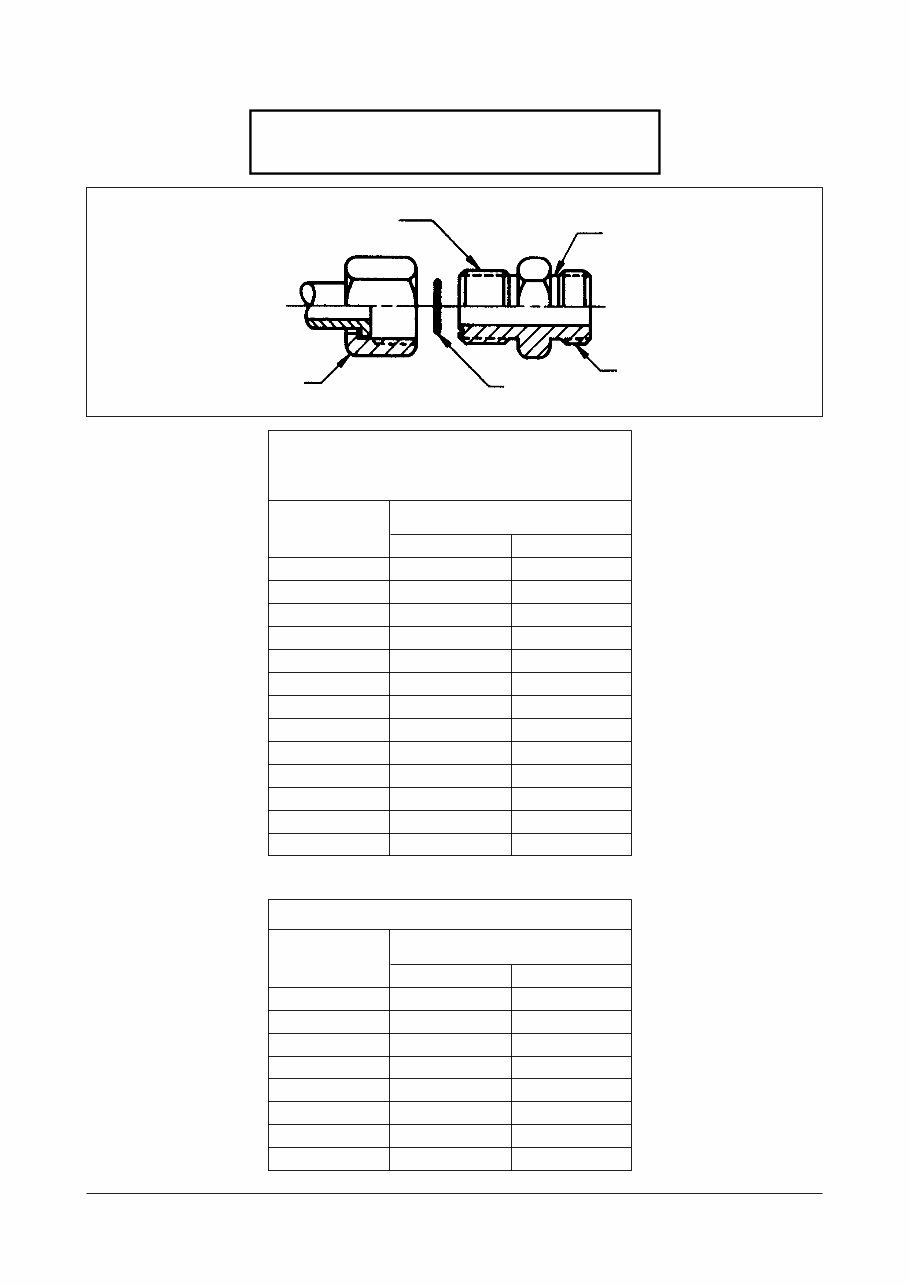
O-RING FACE SEAL FITTINGS
O-RING FACE SEAL FITTING
O-RING FACE SEAL NUT
IDAS001B
O-RING
O-RING GROOVE
STRAIGHT THREAD O-RING
PORT FITTING END
STRAIGHT THREAD O-RING
FITTING (FOR O-RING FACE
SEAL FITTING ONLY)
THREAD
SIZE
inch
5/16-24
3/8-24
7/16-20
1/2-20
9/16-18
3/4-16
7/8-14
1 1/16-12
1 3/16-12
1 5/16-12
1 5/8-12
1 7/8-12
2 1/2-12
(N
i
m)
5.0 – 1.5
12 – 2
20 – 4
30 – 5
40 – 5
100 – 15
135 – 15
200 – 25
250 – 25
300 – 40
300 – 40
300 – 40
300 – 40
(lb
i
ft)
45–15 lb
i
in
110–20 lb
i
in
15 – 3
22 – 4
30 – 4
75 – 10
100 – 10
150 – 20
185 – 20
225 – 30
225 – 30
225 – 30
225 – 30
STANDARD TORQUE
O-RING FACE SEAL FITTING NUT
THREAD
SIZE
inch
9/16-18
11/16-16
13/16-16
1-14
1 3/16-12
1 7/16-12
1 11/16-12
2-12
(N
i
m)
16 – 3
30 – 4
50 – 7
90 – 10
120 – 15
160 – 20
190 – 20
215 – 25
(lb
i
ft)
12 – 2
22 – 3
37 – 5
65 – 7
90 – 10
120 – 15
140 – 15
160 – 20
STANDARD TORQUE
HYDRAULIC LINE INSTALLATION
1. For a metal tube to hose installation, install the tube
and tighten all bolts finger tight.
2. Tighten the bolts at the rigid end.
3. Install the hose and tighten all bolts finger tight.
4. Put the hose in a position so that it does not make
contact with the machine or another hose.
5. Tighten the bolts on both connections.
6. Start the engine.
7. Move the implement control levers to all positions.
8. Look at the hose during movement of the
implement. Make sure hose is not in contact with
the machine or other hoses.
9. Shut off the engine.
10. If necessary, put the hose in a new position where it
will not make contact when the implement is moved.
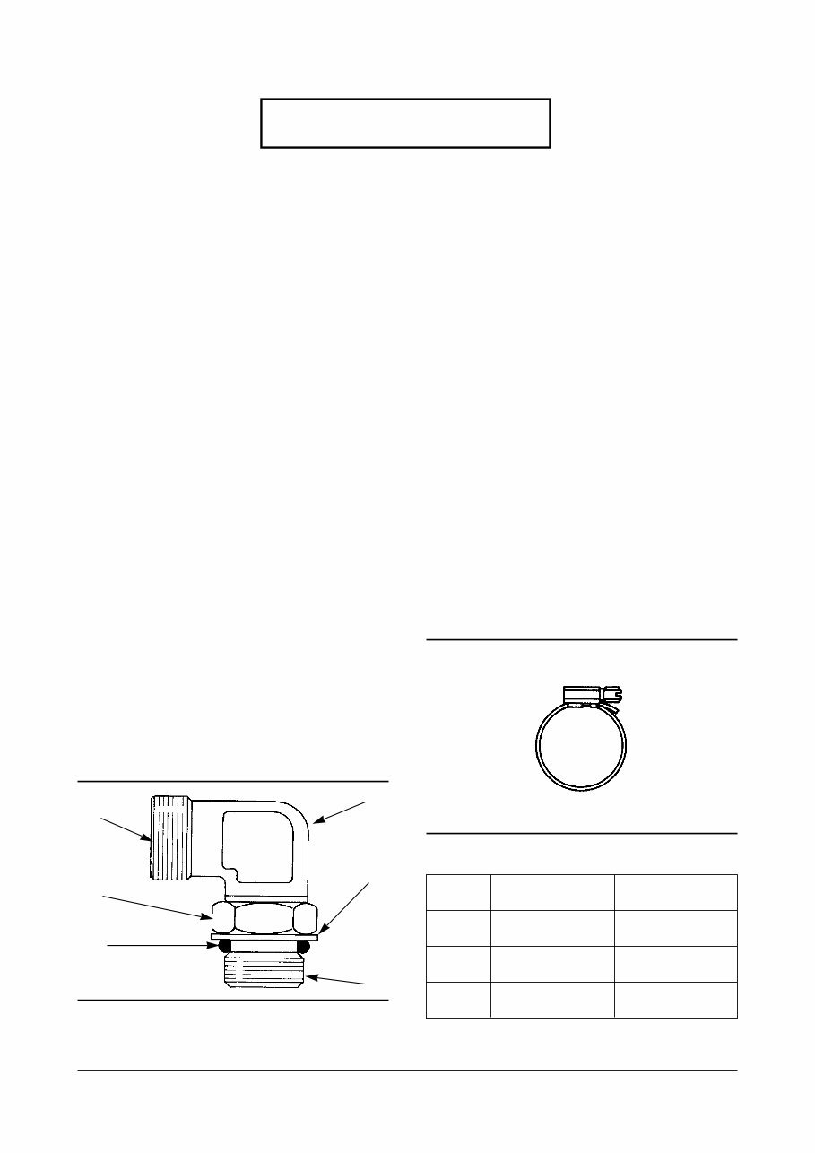
ASSEMBLY OF FITTINGS WITH STRAIGHT
THREADS AND O-RING SEALS
This type of fitting is used in many applications. The tube
end of the fitting will be different in design so that it can
be used in many different applications. However, the
installation procedure of the fitting is the same. If the tube
end of the fitting body is the same as in the illustration
(either an elbow or a straight body) it will be necessary to
assemble the sleeve on the tube before connecting the
tube to the end.
1. Put locknut (3), backup washer (4) and O-ring seal
(5) as far back on fitting body (2) as possible. Hold
these components in this position. Turn the fitting
into the part it is used on until backup washer (4) just
makes contact with the face of the part it is used on.
2. To put the fitting assembly in its correct position, turn
the fitting body (2) out (counterclockwise) a
maximum of 359
ß
. Tighten locknut (3) to the torque
shown in the correct chart for the fitting used.
NOTE: If the fitting is a connector (straight fitting), the
hex on the body takes the place of the locknut. To
install this type fitting, tighten the hex against the face
of the part it goes into.
TORQUES FOR FLARED AND O-RING FITTINGS
The torques shown in the charts that follow are to be
used on the nut part of 37
ß
Flared, 45
ß
Flared and
Inverted Flared fittings (when used with steel tubing),
O-ring plugs, O-ring fittings and swivel nuts when
used in applications to 3000 psi (20 700 kPa).
HOSE CLAMP-BAND TYPE
4 of 7
FITTING INSTALLATION
5
3
1
2
4
6
(1) End of fitting body (connects to tube). (2) Fitting body.
(3) Lock-nut. (4) Backup washer. (5) O-ring seal. (6) End of fitting
that goes into other part.
ELBOW BODY ASSEMBLY
IDAS002B
IDAS003B
CLAMP
WIDTH
7.9 mm
(.312 in)
13.5 mm
(.531 in)
15.9 mm
(.625 in)
TORQUE ON
NEW HOSE
0.9 – 0.2 N
i
m
8 – 2 lb
i
in
4.5 – 0.5 N
i
m
40 – 5 lb
i
in
7.5 – 0.5 N
i
m
65 – 5 lb
i
in
RETIGHTENING
TORQUE
0.7 – 0.2 N
i
m
6 – 2 lb
i
in
3.0 – 0.5 N
i
m
25 – 5 lb
i
in
4.5 – 0.5 N
i
m
40 – 5 lb
i
in
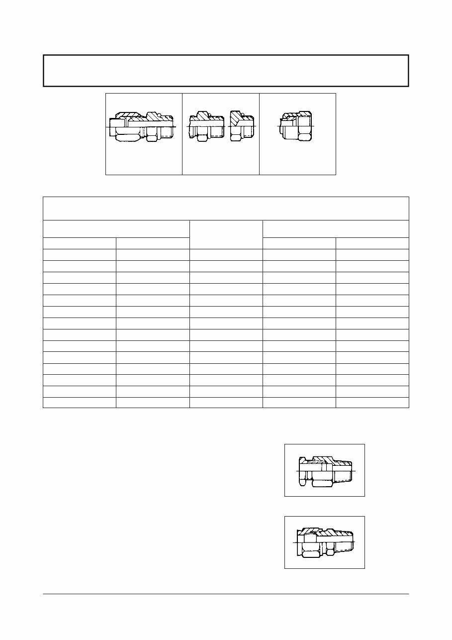
TIGHTENING OTHER FITTINGS
Hi Duty (Shear sleeve) Tube Fittings
After tube has been put through the nut and makes
contact against the tube shoulder in the fitting body,
turn the nut with a wrench until a small decrease in
torque is felt. This is an indication that the sleeve has
been broken off the nut. Hold the tube to prevent
turning and tighten the nut 1-1/2 turns.
Hi Seal Fittings
Put nut and sleeve over the tubing with the short
heavy end of the sleeve facing the end of tubing. Put
the tube end against the counterbore in the body of
the fitting and tighten until nut is over the last thread
on the body. The remainder of space is used
whenever the fitting is removed and installed again.
5 of 7
37
ß
FLARED AND STRAIGHT THREAD O-RING FITTINGS
37
ß
FLARED O-RING
FITTING-PLUG
SWIVEL NUTS
37
ß
FLARED AND STRAIGHT THREAD O-RING FITTINGS
(EXCEPT O-RING FACE SEAL FITTINGS)
NOMINAL TUBE O.D. STANDARD TORQUE
METRIC
3.18
4.76
6.35
7.94
9.52
9.52
12.70
15.88
19.05
22.22
25.40
31.75
38.10
50.80
INCH
.125
.188
.250
.312
.375
.375
.500
.625
.750
.875
1.000
1.250
1.500
2.000
(N
i
m)
5.0 – 1.5
11.0 – 1.5
16 – 2
20 – 5
25 – 5
35 – 5
50 – 7
65 – 7
100 – 10
120 – 10
135 – 15
180 – 15
225 – 15
320 – 30
(lb
i
ft)
4 – 1
8 – 1
12 – 1
15 – 4
18 – 4
26 – 4
37 – 5
48 – 5
75 – 7
90 – 7
100 – 11
135 – 11
165 – 11
240 – 22
THREAD
SIZE
inch
5/16
3/8
7/16
1/2
9/16
5/8
3/4
7/8
1-1/16
1-3/16
1-5/16
1-5/8
1-7/8
2-1/2
IDAS004B
IDAS005B
IDAS006B
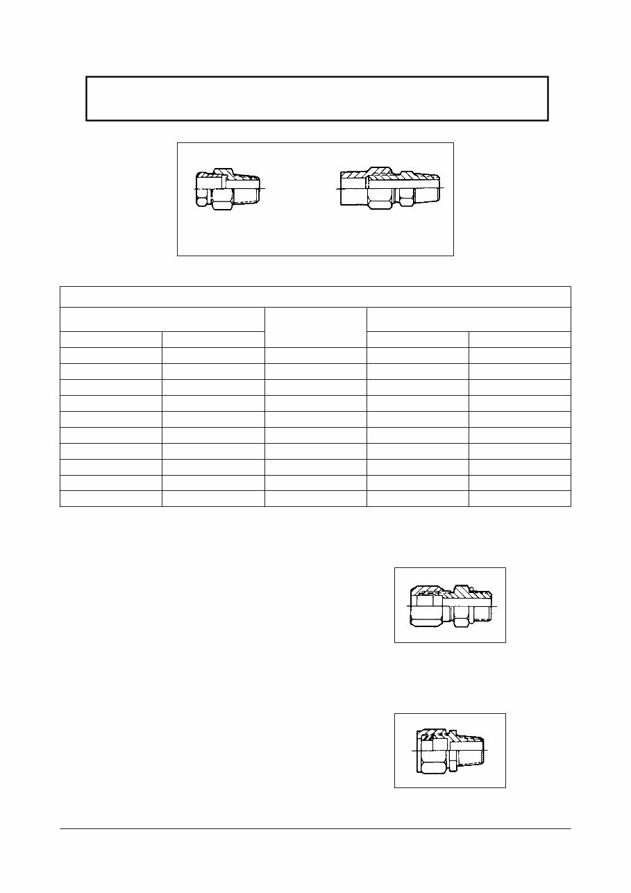
TIGHTENING OTHER FITTINGS
Ermeto Tube Fittings
Put nut and sleeve over the tube with head or
shoulder end of sleeve next to nut. Push tube into
counterbore of fitting body as far as possible. Turn
nut clockwise until sleeve holds tube and prevents
movement. Tighten the nut 1-1/4 turns more to seat
sleeve and give a locking action. When necessary to
assemble again, put sleeve over tube and tighten nut
until a sudden increase in torque is felt. Then tighten
1/6 to 1/3 turn more to seat the sleeve.
Flex Fittings
Put nut and sleeve over the tubing and push tube in
to counterbore of fitting body as far as possible.
Tighten the nut until it is against the hex part of the
fitting body.
6 of 7
45
ß
FLARED AND 45
ß
INVERTED FLARE FITTINGS
INVERTED
45
ß
FLARED 45
ß
FLARED
45
ß
FLARED AND 45
ß
INVERTED FLARE FITTINGS
NOMINAL TUBE O.D. STANDARD TORQUE
METRIC
3.18
4.76
6.35
7.94
9.52
11.11
12.70
15.88
19.05
22.22
INCH
.125
.188
.250
.312
.375
.438
.500
.625
.750
.875
(N
i
m)
5.0 – 1.5
8.0 – 1.5
11 – 2
17 – 3
30 – 3
30 – 3
38 – 4
50 – 5
90 – 8
100 – 10
(lb
i
ft)
4 – 1
6 – 1
8 – 1
13 – 2
22 – 2
22 – 2
28 – 3
37 – 4
65 – 6
75 – 7
THREAD
SIZE
inch
5/16
3/8
7/16
1/2
5/8
11/16
3/4
7/8
1-1/16
1-1/4
IDAS007B
IDAS008B
IDAS009B
You're Reading a Preview
What's Included?
 Lifetime Access
Fast Download Speeds
Online & Offline Access
Access PDF Contents & Bookmarks
Full Search Facility
Print one or all pages of your manual
$52.99
Doosan D20S-5 D25S-5 D30S-5 D33S-5 D35C-5 G20E-5 G25E-5 G30E-5 GC20E-5 GC25E-5 GC30E-5 GC33E-5 G20P-5 G25P-5 G30P-5 G33P-5 G35C-
Viewed 45 Times Today

What's Included?
Lifetime Access
Fast Download Speeds
Online & Offline Access
Access PDF Contents & Bookmarks
Full Search Facility
Print one or all pages of your manual
$52.99

Secure transaction
What's Included?
Lifetime Access
Fast Download Speeds
Online & Offline Access
Access PDF Contents & Bookmarks
Full Search Facility
Print one or all pages of your manual
Description
This manual is an essential resource for anyone working with Doosan D20S-5, D25S-5, D30S-5, D33S-5, D35C-5, G20E-5, G25E-5, G30E-5, GC20E-5, GC25E-5, GC30E-5, GC33E-5, G20P-5, G25P-5, G30P-5, G33P-5, G35C-5, GC20P-5, GC25P-5, GC30P-5, GC33P-5 Fork Lift Trucks. It contains comprehensive operation and maintenance information suitable for both professional technicians and first-time owners or amateurs.
- Information Section
- Foreword
- Safety Section
- Important Safety Information
- Safety
- Warning Signs and Labels
- Parking brake
- General Hazard Information
- Operation Information
- Maintenance Information
- Operator Restraint System (If Equipped)
- Avoiding Lift Truck Tipover
- Safety Rules
- How to Survive in a Tipover
- General Section
- Specifications
- Noise and Vibration
- Capacity Chart (Without/With Sideshifter Pneumatic)
- Capacity Chart (Without/With Sideshifter cushion)
- Serial Number
- Operator's Warning and Identification Plate
- Operation Section
- Operators Station and Monitoring Systems
- Seat Switch System (If Equipped)
- Lift Truck Controls
- Refueling
- Before Starting the Engine
- Starting the Engine
- Dual Fuel System
- Lift Truck Operation
- Mono-Ped Control System
- Auto Shift Controller ASC-100 (If Equipped)
- Operating Techniques
- Parking the Lift Truck
- Lift Fork Adjustment
- Storage Information
- Transportation
- Towing Information
- Maintenance Section
- Inspection, Maintenance and Repair of Lift Truck Forks
- Tire Inflation Information
- Torque Specifications
- Cooling System Specifications
- Fuel Specifications
- Lubricant Information
- Lubricant Viscosities and Refill Capacities
- Maintenance Intervals When Required
- Index Section
- Index
This manual is available in English and is compatible with all versions of Windows and Mac. It is provided in PDF format and requires Adobe Reader for access.


