

Service Manual
ESR4000 Series

Printed in Germany
TABLE OF CONTENT

Printed in Germany
Page intentionally left blank
Seite absichtlich freigelassen
Page intentionellement laissée blanche
Printed in Germany
M-IDX-2140-001
TABLE OF CONTENTS
Index
MA – SAFETY PAGE SER. NO. SEC. ISSUE
Symbols Used In The Manual .............................................. M/P-MA-0000-001 .
General Maintenance and Repair Safety Instructions ........ M/P-MA-0000-001
- Maintenance and Repair ................................................. M/P-MA-0000-002
- Before Parking the Truck ................................................. M/P-MA-0000-002
- Before Working on the Truck ........................................... M/P-MA-0000-002
- Before Starting the Truck ................................................ M/P-MA-0000-002
Truck Warnings and Labels ................................................. M/P-MA-0000-002
ITD – INTRODUCTION PAGE SER. NO. SEC. ISSUE
General ................................................................................. M/P-ITD-2140-001
- Operating Instructions ..................................................... M/P-ITD-2140-001
- Service Training .............................................................. M/P-ITD-2140-001
- Ordering Spare Parts ...................................................... M/P-ITD-2140-001
- Using the Manual ............................................................ M/P-ITD-2140-001
- Page Numbering in the Manual ....................................... M/P-ITD-2140-002
Model Number ...................................................................... M/P-ITD-2140-003
M1 – LUBRICATION AND ADJUSTMENT PAGE SER. NO. SEC. ISSUE
Jacking up the Truck ............................................................ M-1.0-2140-001
Raising the Truck with a Crane ............................................ M-1.0-2140-002
Towing the Truck .................................................................. M-1.0-2140-002
Component Access .............................................................. M-1.0-2140-003
- Removing the Floorboard ................................................ M-1.0-2140-004 ---------------------------------- Rev.1 08/00
- Seat Disassembly / Installation ...................................... M-1.0-2140-004
- Plastic Panel Disassembly / Assembly ........................... M-1.0-2140-004
Maintenance ......................................................................... M-1.1-2140-001
- Driver Participation ......................................................... M-1.1-2140-001
- Daily Maintenance Log .................................................... M-1.1-2140-001
- Recommended Lubricants and Oils ................................ M-1.1-2140-002
- Lubrication Items and Intervals ....................................... M-1.2-2140-001
- Inspection and Maintenance Schedule ............................ M-1.2-2140-002 ---------------------------------- Rev.1 08/00
Torques ................................................................................. M-1.9-0000-001
M2 – HYDRAULICS PAGE SER. NO. SEC. ISSUE
Changing Hydraulic Oil ....................................................... M-2.0-0000-001
Hydraulic Pipes and Accessories ....................................... M-2.1-2140-001
- Filter .......................................................................... M-2.2-2140-002
- Tank ........................................................................... M-2.3-2140-002
- System Bleeding ....................................................... M-2.3-2140-002
- Drift Test .................................................................... M-2.3-2140-002
Funtional Description .......................................................... M-2.3-2140-003
Hydraulic Symbols .............................................................. M-2.3-2140-013
Valve Block ........................................................................... M-2.4-2140-001
- Safety Valve Setting (RV1 and RV2) ............................... M-2.4-2140-001
- Proportional Valve Setting (PVA and PVH) ...................... M-2.4-2140-001
M3 – DRIVE UNIT PAGE SER. NO. SEC. ISSUE
Drive Unit .............................................................................. M-3.1-2140-001
- Removal ......................................................................... M-3.1-2140-001
- Draining the Oil .......................................................... M-3.1-2140-001
- Steering Chain Removal ............................................ M-3.1-2140-002
- Drive Wheel Removal ................................................. M-3.1-2140-002
- Tools ............................................................................... M-3.1-2140-003
Rev.1 08/00
Printed in Germany
M-IDX-2140-002
TABLE OF CONTENTS
- Measurement Tools ......................................................... M-3.1-2140-004
- Equipment ...................................................................... M-3.1-2140-005
Gear Unit Maintenance ......................................................... M-3.1-2140-008
- Disassembly ................................................................... M-3.1-2140-510
- Pre-Assembly Test .......................................................... M-3.1-2140-013
- Assembly ....................................................................... M-3.1-2140-013
- Final Assembly ............................................................... M-3.1-2140-019
- Gear Upper Section Assembly ........................................ M-3.1-2140-021
- Live Ring Bearing Maintenance ....................................... M-3.1-2140-021
- Gear Unit Assembly ........................................................ M-3.1-2140-022
M4 – ELECTRICS PAGE SER. NO. SEC. ISSUE
Electrics - General ................................................................ M-4.0-0000-001
- Wire Colour Codes .......................................................... M-4.0-0000-001
- Abbreviations .................................................................. M-4.0-0000-002
- Electrical Symbols .......................................................... M-4.0-0000-004
Load Monitor (Display) ........................................................ M-4.3-2140-200
- Troubleshooting ............................................................... M-4.3-2140-203
Encoder ECR2 ...................................................................... M-4.3-2140-300
ESR4000 Status Codes ........................................................ M-4.3-2140-400
- Power-up circuit diagram ................................................. M-4.3-2140-401
- Status codes 200 to 294 ................................................. M-4.3-2140-402
- Status codes 311 to 399 ................................................. M-4.3-2140-427
- Status codes 813 to 838 ................................................. M-4.2-2140-403 ---------------------------------- Rev.1 08/00
Access 1-2-3 ......................................................................... M-4.3-2140-600
- Access 1, Design and Function ...................................... M-4.3-2140-600
- Battery Discharge Indicator ....................................... M-4.3-2140-601
- Power "on" ................................................................. M-4.3-2140-601
- Operator Improper Sequence Error ............................. M-4.3-2140-601
- Service Due Key Display .......................................... M-4.3-2140-601
- Navigation Keys ......................................................... M-4.3-2140-602
- Message Display ....................................................... M-4.3-2140-602
- Load Monitor .............................................................. M-4.3-2140-601
Operator Menu .................................................................. M-4.3-2140-603
Service Menu .................................................................... M-4.3-2140-605
Analyzer Menu .................................................................. M-4.3-2140-606
Calibration Menu ............................................................... M-4.3-2140-611
- Accessing the CALIBRATION Menu .......................... M-4.3-2140-613
- When to calibrate ....................................................... M-4.3-2140-613
- Calibration Procedures ............................................... M-4.3-2140-613
- Calibration Complete .................................................. M-4.3-2140-613
Features Menu ................................................................. M-4.3-2140-621
Menü HOUR METERS ...................................................... M-4.3-2140-629 ---------------------------------- Rev.1 08/00
Log Events Menu .............................................................. M-4.3-2140-630
Performance Menu ............................................................ M-4.3-2140-631
Utilities Menu .................................................................... M-4.3-2140-644 ---------------------------------- Rev.1 08/00
Emergency Disconnect Contactor ....................................... M-4.4-2140-001
Battery Maintenance ............................................................. M-4.6-2140-001
Charging the Battery ......................................................... M-4.6-2140-001
Replacing the Battery ........................................................ M-4.6-2140-001
Traction / Pump Motor Maintenance ................................... M-4.35-2140-001
- Access ........................................................................... M-4.35-2140-001
- Maintenance ................................................................... M-4.35-2140-001
M5 – BRAKE PAGE SER. NO. SEC. ISSUE
Brake System ....................................................................... M-5.0-2140-001
- Bleeding the Brake System ............................................ M-5.0-2140-001
- Motor Brake .................................................................... M-5.0-2140-002
Rev.1 08/00
Printed in Germany
M-IDX-2140-003
TABLE OF CONTENTS
- Operating Brake Adjustment ........................................... M-5.0-2140-002
Parking Brake ....................................................................... M-5.0-2140-003
- Parking Brake Adjustment .............................................. M-5.0-2140-003
- Brake System Bleeding .................................................. M-5.0-2140-004
- Motor Brake Disassembly ............................................... M-5.0-2140-004
Load Wheel Brake System ................................................... M-5.0-2140-006
- Load Wheel Brake Adjustment ........................................ M-5.0-2140-006
- Brake System Bleeding .................................................. M-5.0-2140-007
M6 – STEERING PAGE SER. NO. SEC. ISSUE
- Steering .......................................................................... M-6.0-2140-001
- Steering Unit Disassembly ......................................... M-6.0-2140-002
- Hydraulic Motor Disassembly .................................... M-6.0-2140-003
- Steering Chain Adjustment ........................................ M-6.0-2140-004
- POT6 (Steer Angle Display) Replacement ....................... M-6.0-2140-005
- Assembly and Adjustment ......................................... M-6.0-2140-005
M7 – MAST PAGE SER. NO. SEC. ISSUE
Mast ...................................................................................... M-7.0-2140-001
- Torque Requirements ...................................................... M-7.0-2140-001
- Fork Adjustments ........................................................... M-7.0-2140-001
- Mast Testing (Assembled) ............................................... M-7.0-2140-001
- Flaking ............................................................................ M-7.0-2140-001
- Shock Absorbers ............................................................ M-7.0-2140-001
- Mast Dampening Screws, Adjustment ............................ M-7.0-2140-001
- Mast Disassembly .......................................................... M-7.0-2140-003
- Mast Assembly .............................................................. M-7.0-2140-003
- Mast Rollers ................................................................... M-7.0-2140-004
- Mast Roller Adjustment ............................................. M-7.0-2140-004
- Mast Play Control ...................................................... M-7.0-2140-004
- Fork Carriage .................................................................. M-7.0-2140-006
- Disassembly .............................................................. M-7.0-2140-006
- Assembly .................................................................. M-7.0-2140-006
- Fork Carriage Roller Adjustment ................................ M-7.0-2140-007
Lift Chains ............................................................................ M-7.5-2140-001
- General ........................................................................... M-7.5-0000-001
- Inspection ....................................................................... M-7.5-0000-001
- Cleaning .................................................................... M-7.5-0000-001
- Wear .......................................................................... M-7.5-0000-001
- Freedom of Movement ............................................... M-7.5-0000-002
- Chain Tension ............................................................ M-7.5-0000-002
- Chain Anchor and Pulleys .......................................... M-7.5-0000-002
- Worn or Missing Plates .............................................. M-7.5-0000-002
- Protruding or Turned Chain Pins ................................. M-7.5-0000-002
- Corrosion ................................................................... M-7.5-0000-003
- Chain Lateral Wear ..................................................... M-7.5-0000-003
- Uneven Chain Tension ................................................ M-7.5-0000-003
- Misalignment of Lift Components ............................... M-7.5-0000-003
- Lift Chain Lubrication ...................................................... M-7.6-0000-001
Fork Tine Test ....................................................................... M-7.6-0000-002
- General ........................................................................... M-7.6-0000-002
- Fork Identification ........................................................... M-7.6-0000-002
- Repairs ........................................................................... M-7.6-0000-002
- Crack Inspection ............................................................. M-7.6-0000-002
- Fork Identification ........................................................... M-7.6-0000-002
- Fork Blade Warping ......................................................... M-7.6-0000-003
- Verticality Test ................................................................ M-7.6-0000-003
- Measuring the Fork Tip Width .......................................... M-7.6-0000-004
- Fork Tine Height Difference ............................................. M-7.6-0000-004
Printed in Germany
M-IDX-2140-004
TABLE OF CONTENTS
- Fork Stop ........................................................................ M-7.6-0000-004
- Wear ............................................................................... M-7.6-0000-005
M8 – CYLINDERS PAGE SER. NO. SEC. ISSUE
General ................................................................................. M-8.0-0000-001
- Plunger Cylinders ............................................................ M-8.0-0000-001
- Piston Cylinder ............................................................... M-8.0-0000-002
- Maintenance ................................................................... M-8.0-0000-003
- Inspection ....................................................................... M-8.0-0000-003
Installing the Piston Seals .................................................. M-8.0-2340-001
Cylinder Disassembly .......................................................... M-8.0-2340-002
- Free-Lift Cylinder Disassembly and Assembly ................ M-8.0-2340-002
- Lift Cylinder Disassembly and Assembly ........................ M-8.6-2340-002
- Reach Cylinder Disassembly and Assembly ................... M-8.6-2340-002
- Sideshifter Cylinder Disassembly and Assembly ............ M-8.6-2340-003
- Tilt Cylinder Disassembly and Assembly ........................ M-8.6-2340-003
- Parking Brake Cylinder Disassembly and Assembly ....... M-8.6-2340-002
DIA – WIRING DIAGRAMS PAGE SER. NO. SEC. ISSUE
Standard Layout ................................................................... M/P-DIA-2140-001
- Control Circuit ................................................................. M/P-DIA-2140-001------------------------------- Rev.2 09/00
- Acces1 ........................................................................... M/P-DIA-2140-002------------------------------- Rev.2 09/00
- Access2 ......................................................................... M/P-DIA-2140-003
- Access3 ......................................................................... M/P-DIA-2140-004
- Switches and Controls .................................................... M/P-DIA-2140-005
- Mast, Hydraulic Components .......................................... M/P-DIA-2140-008------------------------------- Rev.2 09/00
- Fuses, Fans and Contactors ........................................... M/P-DIA-2140-008
- Node points .................................................................... M/P-DIA-2140-011------------------------------- Rev.2 09/00
- Power cable .................................................................... M/P-DIA-2140-013
HYD – HYDRAULIC DIAGRAM PAGE SER. NO. SEC. ISSUE
Hydraulic Diagram ............................................................. M/P-HYD-2140-001------------------------------ Rev.1 09/00
Rev.2 09/00

Printed in Germany
SAFETY

Printed in Germany
Page intentionally left blank
Seite absichtlich freigelassen
Page intentionellement laissée blanche
Printed in Germany
1 M/P-MA-0000-001
SAFETY
OPTION
Safety Symbols used in the
Manual
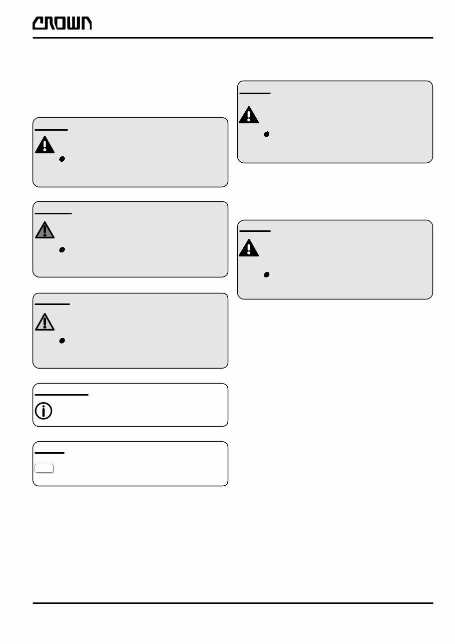
To help guide you through the manual and to highlight
particular danger areas, we have used graphic illustra-
tions:
DANGER
This symbol indicates life-threatening risks
Failure to comply with this notice may
result in severe or fatal injuries to yourself
or other people.
WARNING
This symbol indicates the risk of serious
injury and/or serious material damage.
Failure to comply with this notice may
result in severe injuries to yourself or other
people and/or serious material damage.
CAUTION
This symbol indicates the risk of minor
injury and/or minor material damage.
Failure to comply with this notice may
result in minor injuries to yourself or other
people and/or minor material damage.
INFORMATION
Contains additional information with
supplementary notes and hints.
OPTION
These items relate to optional features not
supplied with the standard version.
General Maintenance and Repair
Safety Notes
DANGER
Read the safety notices in the truck Mainte-
nance and Operator's Manuals.
Failure to do so could result in severe or
fatal injuries to maintenance personnel
and/or other persons.
Motorised vehicles can be dangerous if maintenance
and service are neglected. For this reason maintenance
and inspections must be carried out at regular short
intervals by trained personnel working to approved
company guidelines.
DANGER
Follow all national/local safety regulations
applicable for maintenance work, e.g. for
work on higher levels.
Failure to do so could result in severe or
fatal injuries to maintenance personnel and/
or other persons.
Maintenance and Repair
1. Maintenance work must only be carried out in
accordance with the test and maintenance pro-
gram contained in the present Maintenance
Manual and any applicable service notices.
2. Only qualified and authorised personnel may
carry out work on the truck.
3. Always keep fire extinguishers in good working
condition. Do not approach fluid levels or leaks
with a naked flame.
4. To clean, use a non flammable, non combustible
cleaning solution which is groundwater-neutral.
Only carry out cleaning with an oil separator.
Protect the electrical system from dampness.
5. Keep the service area clean, dry and well-venti-
lated.
6. Do not allow oil to penetrate the ground or enter
the draining system. Used oil must be recycled.
Oil filters and desiccants must be treated as
special waste products. Relevant applicable
regulations must be followed.
You're Reading a Preview
What's Included?
Fast Download Speeds
Online & Offline Access
Access PDF Contents & Bookmarks
Full Search Facility
Print one or all pages of your manual
$66.99
CROWN Lift Truck ESR4000 Series Service Maintenance Manual
Viewed 25 Times Today

What's Included?
Fast Download Speeds
Online & Offline Access
Access PDF Contents & Bookmarks
Full Search Facility
Print one or all pages of your manual
$66.99

Secure transaction
What's Included?
Fast Download Speeds
Online & Offline Access
Access PDF Contents & Bookmarks
Full Search Facility
Print one or all pages of your manual
Description
The CROWN LIFT TRUCK ESR4000 Series Service Workshop Shop Repair Maintenance Manual is a comprehensive resource for anyone involved in the repair and maintenance of CROWN ESR4000 series lift trucks. This manual contains detailed procedures, diagrams, and specifications that are essential for troubleshooting, servicing, and repairing the ESR4000 series lift trucks.
Whether you are a professional mechanic or a DIY enthusiast, this manual provides valuable insights into the inner workings of the ESR4000 series lift trucks. It covers a wide range of topics including engine, electrical system, hydraulics, and more, making it an indispensable tool for maintaining and repairing these vehicles.


