CONTENTS SM 795 CONTENTS Contents by Group and Section (Alphabetical listing of contents appears on next page.) Contents are listed here by Group number and name followed by Section number and name: SA SAFE MAINTENANCE 1. Safety 2. Lifting, Jacking, and Blocking the Truck 3. Towing PS PERIODIC SERVICE 1. Maintenance Schedules 2. Planned Maintenance Program 3. The PM Inspection Form 12 BATTERY 1. Battery Service 13 WIRING, SWITCHES, AND INSTRUMENTS 1. Schematic Electric Circuit Diagrams 2. General Electrical Service Tips 3. Wiring and Cables 4. Switches and Sensors 5. Instrument Panel 16 ELECTRIC MOTORS 1. Motor Specifications And Descriptions 2. Drive Motors Overhaul 3. Pump Motor Overhaul 17 CONTACTORS 1. Contactors Specification and Overhaul 19 MOTOR CONTROLS 1. Description 2. Control Programming 3. Control troubleshooting 4. GEX Factory Control Settings 20 DRIVE AXLE 1. Specifications and Description of Drive Axle 2. Disassembly of Drive Axle 3. Disassembly of wheel Assembly 4. Adjustment 22 WHEELS AND TIRES 1. Wheels & Tires Specifications and Description 2. Wheels & Tires Mounting and Maintenance 23 BRAKE SYSTEM 1. Brake System Specifications and Description 2. Service Brake Troubleshooting 3. Brake Pedal Linkage & Adjustments 4. Brake Bleeding 5. Pedal and Master Cylinder Service 6. Parking Brake Service 25 STEERING SYSTEM (GEX16-20s) 1. Steering System Specifications and Description. 2. Steering System Troubleshooting 3. Steering Column Removal and Replacement 4. Steering System Relief Pressure Check and Adjustment 5. Steering Axle Wheel Bearing Maintenance and Adjustment 6. Steering Axle Removal and Replacement 7. Steer Cylinder Removal and Replacement 8. Steering Gear Overhaul 9. Steer Cylinder Overhaul 26 STEER SYSTEM (GTX16-20s) 1. Steering System Specifications and Description. 2. Steering System Troubleshooting 3. Steering Column Removal and Replacement 4. Steering System Relief Pressure Check and Adjustment 5. Steering Gear Overhaul 6. Steer Axle Service 7.Steering Gear Overhaul(ELH Optional) 29 HYDRAULIC SUMP, FILTERS, AND PUMP 1. Main Hydraulic System Specifications and Description 2. Main Hydraulic Pump Troubleshooting 3. Main Hydraulic Pump Removal and Installation 30 HYDRAULIC SYSTEM 1. Hydraulic Control Valve/Lift Circuit Specifications and Description 2. Hydraulic System Schematic 3. Hydraulic System Troubleshooting 4. Hydraulic Sysrem Pressure Checks and Adjust- ments 5. Hydraulic Control Valve Removal and Replacement 6. Hydraulic Control Valve Overhaul 32 TILT CYLINDERS 1. Tilt Cylinder Specifications and Description 2. Checks and Adjustments 3. Tilt Cylinder Removal and Installation 4. Tilt Cylinder Overhaul 34 UPRIGHTS 1. Upright Specifications and Description 2. Trouble shooting 3. Upright Inspection 4. Carriage and Upright Roller Clearance Checks and Shim Adjustment 5. Cylinder Removal, Shimming, Overhaul and Replacement 6. Upright Chain Inspection, Adjustment and Replace- ment 7. Fork and Carriage Removal and Replacement 8. Upright Removal and Replacement
CONTENTS SM 785 CONTENTS 38 COUNTERWEIGHT AND CHASSIS 1. Counterweight Specifications and Description 2. Counterweight Removal and Installation 3. Overhead Guard Removal and Installation 4. Floor Plate, Seat, and Seat Deck Removal and Installation 40 SPECIFICATIONS 1. Nameplate and Decals 2. General Specifications 3. Hydraulic Fitting Tightening Procedure
GROUP SA SM 795 SA-0 GROUP SA SAFE MAINTENANCE Safety ................................................................. Section 1 Lifting, Jacking, and Blocking the Truck........ Section 2 Towing ............................................................... Section 3
Group SA, Safe Maintenance SM 795 SA-1-1 Safety Signs and Messages ............................................... 2 Safe Maintenance Practices ............................................... 2 Section 1. Safety
Group SA, Safe Maintenance SM 795 SA-1-2 Safety Signs and Messages Safety signs and messages in this manual and on the lift truck provide instructions and identify specific areas where potential hazards exist and special precautions should be taken. Be sure you know and understand the meaning of these instructions, signs, and messages. Dam- age to the truck, death, or serious injury to you or other persons may result if these messages are not followed. NOTE This message is used when special informa- tion, instructions or identification is required relating to procedures, equipment, tools, pressures, capacities, and other special data. IMPORTANT This message is used when special precau- tions should be taken to ensure a correct action or to avoid damage to, or malfunction of, the truck or a component. CAUTION ! This message is used as a reminder of safety hazards that can result in personal injury if proper precautions are not taken. WARNING ! This message is used when a hazard exists that can result in injury or death if proper precautions are not taken. DANGER ! This message is used when an extreme haz- ard exists that can result in injury or death or serious injury if proper precautions are not taken. The above terms have been adopted by Clark Material Handling Company. The same terms may be used in dif- ferent context in service literature supplied directly or indirectly by vendors of truck components.. Safe Maintenance Practices The following instructions have been prepared from cur- rent industry and government safety standards applicable to industrial truck operation and maintenance. These rec- ommended procedures specify conditions, methods, and accepted practices that aid in the safe maintenance of industrial trucks. They are listed here for the reference and safety of all workers during maintenance operations. Carefully read and understand these instructions and the specific maintenance procedures before attempting to do any repair work. When in doubt of any maintenance procedure, please con- tact your local Clark dealer. 1. Powered industrial trucks can become hazardous if maintenance is neglected. Therefore, suitable main- tenance facilities, trained personnel, and procedures must be provided. 2. Maintenance and inspection of all powered industrial trucks shall be done in conformance with the manu- facturer’s recommendations. 3. A scheduled planned maintenance, lubrication, and inspection program shall be followed. 4. Only trained and authorized personnel shall be per- mitted to maintain, repair, adjust, and inspect indus- trial trucks. Work should be performed in accordance with the manufacturer’s specifications. 5. Properly ventilate work area, vent exhaust fumes, and keep shop clean and floor dry. 6. Avoid fire hazards and have fire protection equip- ment present in the work area. Do not use an open flame to check for level or leakage of fuel, electro- lyte, oil, or coolant. Do not use open pans of fuel or flammable cleaning fluids for cleaning parts. 7. Before starting work on truck: a. Raise drive wheels off of floor and use blocks or other positive truck positioning devices. b. Disconnect battery before working on the electri- cal system. 8. Before working on engine fuel system of gasoline- or diesel-powered trucks, be sure the fuel shut-off valve is closed. 9. Operation of the truck to check performance must be conducted in an authorized, safe, clear area. 10. Before starting to drive truck: a. Be in operating position with seat belt fastened. b. Be sure parking brake is engaged. c. Put direction control in neutral. d. Start engine. e. Check functioning of direction and speed controls, steering, brakes, warning devices, and any load handling attachments. 11. Before leaving truck a. Stop truck. b. Put directional control in neutral. c. Apply the parking brake.
Group SA, Safe Maintenance SM 795 SA-1-3 d. Stop the engine by turning off the key switch. e. Put upright in vertical position and fully lower the forks or attachment. f. Put blocks at the wheels if truck is on an incline. 12. Brakes, steering mechanisms, control mechanisms, warning devices, lights, governors, guards, safety devices, and frame members must be carefully and regularly inspected and maintained in a safe operat- ing condition. 13. Special trucks or devices designed and approved for hazardous area operation must receive special atten- tion to ensure that maintenance preserves the origi- nal, approved, safe-operating features. 14. Fuel systems must be checked for leaks and condi- tion of parts. Extra special consideration must be given in the case of a leak in the fuel system. Action must be taken to prevent the use of the truck until the leak has been corrected. 15. The truck manufacturer’s capacity, operation, and maintenance instruction plates, tags, or decals must be maintained in legible condition. 16. Batteries, motors, controllers, limit switches, protec- tive devices, electrical conductors, and connections must be inspected and maintained in conformance with good practice. Special attention must be paid to the condition of electrical insulation. 17. To avoid injury to personnel or damage to the equip- ment, consult the manufacturer’s procedures in replacing contacts on any battery connection. 18. Industrial trucks must be kept in a clean condition to minimize fire hazards and help in the detection of loose or defective parts. 19. Modifications and additions that affect capacity and safe truck operation must not be done without the manufacturer’s prior written approval. Capacity, operation and maintenance instruction plates, tags, or decals must be changed accordingly. This is an OSHA requirement. 20. Care must be taken to assure that all replacement parts, including tires, are interchangeable with the original parts and of a quality at least equal to that provided in the original equipment. Parts, including tires, are to be installed per the manufacturer’s proce- dures. Always use genuine CLARK or CLARK- approved parts. 21. Use special care when removing heavy components from the truck, such as counterweight, seat deck, upright, etc. Be sure that lifting and handling equip- ment is of the correct capacity and in good condition. Also, this removal may upset the stability of the truck. The frame must always be safely blocked for major component removal. NOTE You should also be familiar with additional operating and maintenance safety instruc- tions contained in the following publications: ASME B56.1 - 1988: Operator Control-Industrial Tow Tractors (Safety Standard For Powered Industrial Trucks). Published by: American Society of Mechanical Engi- neers, Three Park Avenue, New York, NY10016. NFPA 505-1982: Fire Safety Standard for Powered Indus- trial Trucks: Type Designations, Areas of Use, Mainte- nance and Operation. Available from: National Fire Protection Assoc., Inc., Batterymarch Park, Quincy, MA 02269. General Industrial Standards, OSHA 2206: OSHA Safety and Health Standards (29 CFR 1910), Subpart N-Materi- als Handling and Storage, Section 1910.178 Powered Industrial Trucks. For sale by: Superintendent of Docu- ments, U.S. Government Printing Office, Washington, DC 20402.
Group SA, Safe Maintenance SM 795 SA-2-1 Raising Drive Wheels ..................................................... 2 Chaining the Upright in Raised Position ...................... 2 Raising Rear of Truck ..................................................... 3 Raising Entire Truck ....................................................... 4 Shipping Tie-Down Instructions.................................... 4 WARNING ! Lifting or jacking any large piece of equipment such as a fork truck presents obvious hazards. It must be done with great care and forethought. Consult the truck weight information in Group 40, Specifications, to ensure that your lifting equipment is of adequate capacity. Section 2 Lifting, Jacking, and Blocking
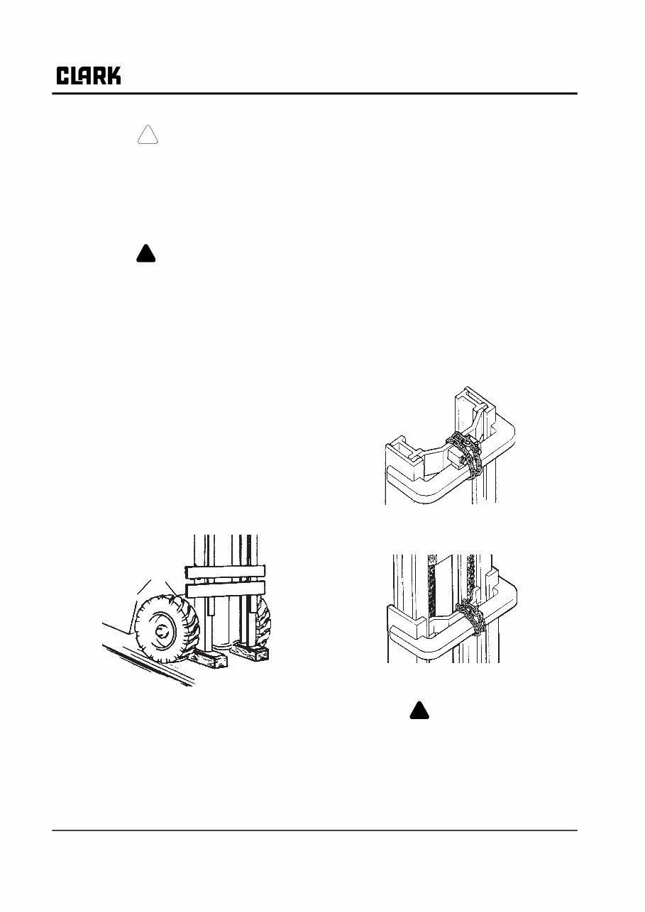
Group SA, Safe Maintenance SM 795 SA-2-2 CAUTION ! To perform these service procedures, first: . Park truck on a level surface. . Put the upright in a vertical position and lower the carriage fully down. . Return control handle to neutral and turn key switch OFF. WARNING ! Defective equipment can cause accidents. All tools and lifting equipment must be in good condition, meet the load capacity require- ments and have OSHA labels when required. Tools with defects can fail, causing severe injury or death. Raising Drive Wheels This procedure uses the upright to lift the drive wheels off the floor. 1. Park the truck safely. 2. Turn key switch ON. Tilt the upright fully back. 3. Put a solid 100 x 100 mm (4 x 4 inch) hardwood block under the front section of each upright rail. Put a 3 ~ 6 mm (0.125 ~ 0.250 inch) steel plate on top of each block. 4. Tilt the upright fully forward. This will raise the drive wheels off the floor. 5. Block the truck under the frame behind the drive wheels with solid blocking. 6. Turn key switch OFF. 7. Check for safe clearance between drive wheels, block and floor. 8. Check the stability of the truck. Be sure that the blocks are located securely under the frame before operating the drive motor or working on truck. 9. Lower the drive wheels to the floor by reversing this procedure. . Turn key switch ON. . Tilt upright fully back. . Turn key switch OFF. 10. Remove the blocks from under the frame and upright rails. Chaining the Upright in Raised Posi- tion This procedure provides safe clearance for access from the front of truck to components on or near the drive axle. 1. Park truck safely. 2. Put blocks at front of and rear of drive wheels. 3. Raise upright carriage. 4. Chain the center inner rail tie bar to the top outer rail tie bar as shown. Triple Stage Uprights: Chain the center intermediate rail tie bar and the lower inner rail tie bar to the top outer rail tie bar. 5. Reverse the procedure to remove the chains. WARNING ! Keep hands, tools, etc. out of upright.
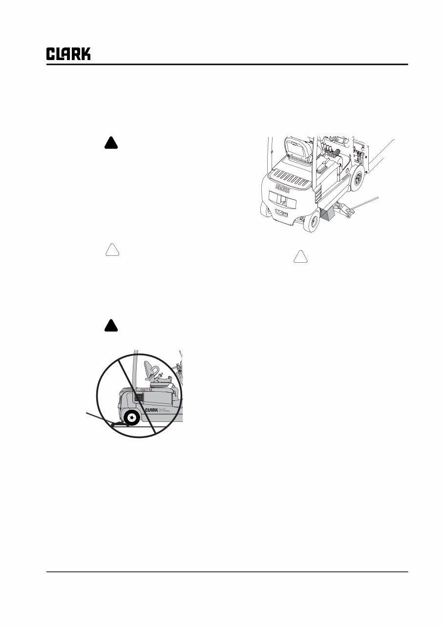
Group SA, Safe Maintenance SM 795 SA-2-3 Raising Rear of Truck The truck may be raised at the rear by jacking and block- ing under the frame just beyond the counterweight. Refer to truck data plate for truck weights. WARNING ! An incorrectly installed counterweight can move or fall unexpectedly. NEVER LIFT OR BLOCK A TRUCK USING THE COUN- TERWEIGHT. Failure to follow procedures outlined in this manual can result in injury or death. 1. Park truck safely. 2. Put blocks at front and rear of drive wheels. CAUTION ! If possible, remove the battery from truck to reduce weight for added safety and ease of jacking. 3. Put a floor jack under the frame just beyond the coun- terweight. WARNING ! Never lift the truck by the counterweight. NOTE If there is insufficient clearance under frame for your jack, the truck may first be driven onto shims, such as 25 x 150 x 300 mm (1 x 6 x 12 in) pieces of board, to increase the truck frame under-clearance. 4. Jack up one side of the truck about 50 mm (2 in) and put a block under the frame to hold that elevation. Then move the jack to the other side and jack and block it. Continue to alternate the procedure from side to side, increasing elevation not more than 50 mm (2 in) each time. Raise the truck no higher than necessary to perform the maintenance work. Make sure the left and right sides of the truck are finally blocked in a level working position. CAUTION ! Before performing any maintenance work, check the truck for stable condition on the blocking by determining that it will not rock on blocks. 5. When maintenance work is completed, lower the rear of truck to the floor by reversing the above procedure and lowering each side of the truck 50 mm (2 in) at a time: • Put jack under frame and raise truck. • Carefully remove blocks and lower truck. • Remove jack and blocks from drive wheels.
You're Reading a Preview
What's Included?
Lifetime Access
Fast Download Speeds
Online & Offline Access
Access PDF Contents & Bookmarks
Full Search Facility
Print one or all pages of your manual
$41.99
CLARK Forklift GEX16, GEX18, GEX20s (4 Wheel), GTX16, GTX18, GTX20s (3 Wheel) Service Repair Manual
This is a comprehensive Service Repair Manual for the CLARK FORKLIFT GEX16, GEX18, GEX20s (4 Wheel), GTX16, GTX18, GTX20s (3 Wheel). It contains in-depth information about maintenance, assembly, disassembly, and servicing of the mentioned forklift models.
Models Covered:
CLARK FORKLIFT GEX16 (4 Wheel)
CLARK FORKLIFT GEX18 (4 Wheel)
CLARK FORKLIFT GEX20s (4 Wheel)
CLARK FORKLIFT GTX16 (3 Wheel)
CLARK FORKLIFT GTX18 (3 Wheel)
CLARK FORKLIFT GTX20s (3 Wheel)
Table of Contents:
SA SAFE MAINTENANCE
1. Safety
2. Lifting, Jacking, and Blocking the Truck
3. Towing
PS PERIODIC SERVICE
1. Maintenance Schedules
2. Planned Maintenance Program
3. The PM Inspection Form
12 BATTERY
1. Battery Service
Model Specification: CLARK FORKLIFT GEX16, GEX18, GEX20s (4 Wheel), GTX16, GTX18, GTX20s (3 Wheel)
Language: English
Total Pages: 425
File Format: .PDF
Requirements: Adobe Reader
ZOOM IN/OUT: YES
Printable: YES
Compatible: All Versions of Windows & Mac
This manual contains information, data, specs, diagrams, actual real photo illustrations, and schemes. It is useful for diagnosing, repairing, and maintaining CLARK machinery. The manuals are compatible with Windows 7, Vista 32 and 64, XP, ME, 98, NT, 2000, and Mac.
Tons of pictures and diagrams are included, making it easy for any skill level to follow the step-by-step instructions. All pages are printable, allowing you to run off what you need and take it with you into the garage or workshop, ultimately saving money by doing your own repairs.
Reviews
Q&A
Recently Viewed
5,521,897Happy Clients
2,594,462eManuals
1,120,453Trusted Sellers
15Years in Business
Price:
Actual Price:
CLARK Forklift GEX16, GEX18, GEX20s (4 Wheel), GTX16, GTX18, GTX20s (3 Wheel) Service Repair Manual










 Lifetime Access




