

Clark forklift c20b Manual
What's Included?
Fast Download Speeds
Online & Offline Access
Access PDF Contents & Bookmarks
Full Search Facility
Print one or all pages of your manual

TM 10-3930-237-35
DEPARTMENT OF THE ARMY TECHNICAL MANUAL
DS, GS, AND DEPOT MAINTENANCE MANUAL
TRUCK, LIFT, FORK, GASOLINE
SOLID RUBBER TIRED WHEELS
2000 POUND CAPACITY
ARMY MODEL MHE-192
CLARK MODEL C20B-1632032-100
FSN 3930-781-3857
CLARK MODEL C20B-1632033-127
FSN 3930-781-3858
This copy is a reprint which includes current
pages from Change 1.
HEADQUARTERS, DEPARTMENT OF THE ARMY
SEPTMEBER 1964

TM 10-3930-237-35
Changes in force: C1 C1
CHANGE HEADQUARTERS
DEPARTMENT OF THE ARMY
NO. 1 WASHINGTON, DC 25 March 1985
DIRECT SUPPORT, GENERAL SUPPORT AND
DEPOT MAINTENANCE MANUAL
TRUCK, LIFT, FORK, GASOLINE
SOLID RUBBER TIRED WHEELS
2000 POUND CAPACITY
ARMY MODEL MHE-192
CLARK MODEL C20B-1632032-100
(NSN 3930-00-781-3857)
CLARK MODEL C20B-1632033-127
(NSN 3930-00-781-3858)
TM 10-3930-237-35, September, 1964 is changed as
follows:
Title appearing on front cover and page 1 changed as
shown above:
Inside front cover add the following:
WARNING
Operation of this equipment presents
a noise hazard to personnel in the
area. The noise level exceeds the
allowable limits for unprotected
personnel. Wear ear muffs or ear
plugs which were fitted by a trained
professional.
WARNING
Compressed air, used for cleaning
purposes will not exceed 30 psi (207
kPa). Wear face shield and protective
clothing to prevent injury when using
compressed air.
WARNING
Drycleaning solvent P-D-680 is toxic
and flammable. Wear protective
goggles and gloves and use only in a
well ventilated area. Avoid contact
with skin, eyes, and clothes and don’t
breath vapors. Do not use near open
flame or excessive heat. The flash
point is 100°F - 138°F (38°C - 59°C). If
you become dizzy while using
cleaning solvent, get fresh air
immediately and get medical aid. If
contact with eyes is made, wash your
eyes with water and get medical aid
immediately.
WARNING
Cooling system is pressurized.
Remove cap slowly and only when
engine is cool or painful burns could
result.
}
TM 10-3930-237-35
C1
Page 12:
Paragraph 11, immediately following the title add the
following:
WARNING
Compressed air, used for cleaning
purposes will not exceed 30 psi (207
kPa). Wear face shield and protective
clothing to prevent injury when using
compressed air.
Paragraph 11.c. is superseded as follows:
c. Cylinder Head
Removal.
(1) Drain coolant from the radiator and engine.
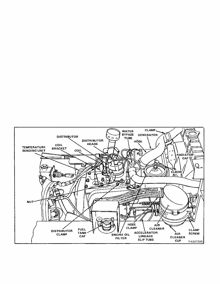
(2) Remove hydraulic tank filler pipe and air cleaner
(fig. 4.1). Cover sump elbow to keep dirt or part
from falling in.
(3) Tag and remove high-tension and primary
distributor wire from coil (fig. 4.1).
(4) Remove nuts and lockwashers that secure
transmission oil filter and coil bracket to head
and block. Position bracket to provide clearance
to remove cylinder head.
(5) Loosen generator adjusting strap bolt (fig. 4.1).
Push generator toward engine. Remove belts
from generator pulley.
(6) Remove generator adjusting strap bolt, washer,
and lockwasher. Remove nuts and washers
securing generator to cylinder head.
(7) Remove nuts and washer securing thermostat
housing to cylinder head.
(8) Remove the bypass elbow (fig. 4.1) from the
water pump and thermostat elbow; remove the
thermostat housing.
(9) Remove nuts and washers (fig. 4.1) securing
engine oil filter to cylinder head studs.
(10) Remove distributor (see TM 10-3930-237-20).
(11) Tag and disconnect the lead from the water
temperature sending unit (fig. 4.1). Remove the
sender.
Figure 4.1. Engine compartment, left view.
TM 10-3930-237-35
C1
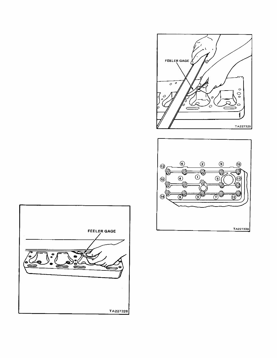
(12) Remove the nuts and washers securing the
cylinder head (fig. 4.4). Remove the cylinder
head and gasket.
c.1 Cleaning and Inspection.
(1) Remove all carbon from combustion areas with
a scraper and wire brush. Clean all remaining
residue from the cylinder head with an approved
cleaning solvent. Dry with clean, dry
compressed air.
(2) Clean the top of the cylinder block with a scraper
and a cloth dampened in an approved cleaning
solvent. Be very careful not to get dirt in the
cylinders or water jacket.
(3) Inspect the cylinder head for cracks, corrosion,
damaged threads, plugged water ports, or other
defects.
(4) Check flatness lengthwise with a straightedge
and feeler gage (fig. 4.2). The maximum
permissible low spot is 0.004 inch in the center,
gradually decreasing toward the ends. Check
flatness lengthwise at each edge and in the
middle of the head.
(5) Check flatness crosswise with a straightedge
and a filler gage (fig. 4.3). The maximum
permissible low spot is 0.003 inch in localized
areas. Check flatness crosswise at each end
and between each combustion chamber.
(6) Inspect cylinder head studs for looseness or
damaged threads.
(7) Replace the gasket hoses and defective parts.
Figure 4.2. Checking cylinder head flatness lengthwise.
Figure 4.3. Checking cylinder head flatness crosswise.
Figure 4.4. Cylinder head nut tightening sequence.
Page 22, paragraph 11.o. is superseded as follows:
o. Installation. Install head and other parts in
reverse order of removal and retime engine if necessary.
(see TM 10-3930-237-20).
TM 10-3930-237-35
C1
Page 24:
Paragraph 13.a.(1), change (TM 10-3930-237-20) to
paragraph 11.c.
Paragraph 13.a.(2), change (TM 10-3930-237-20) to
paragraph 13.c. below.
Page 27, after paragraph 13.b.(11) add the following new
section:
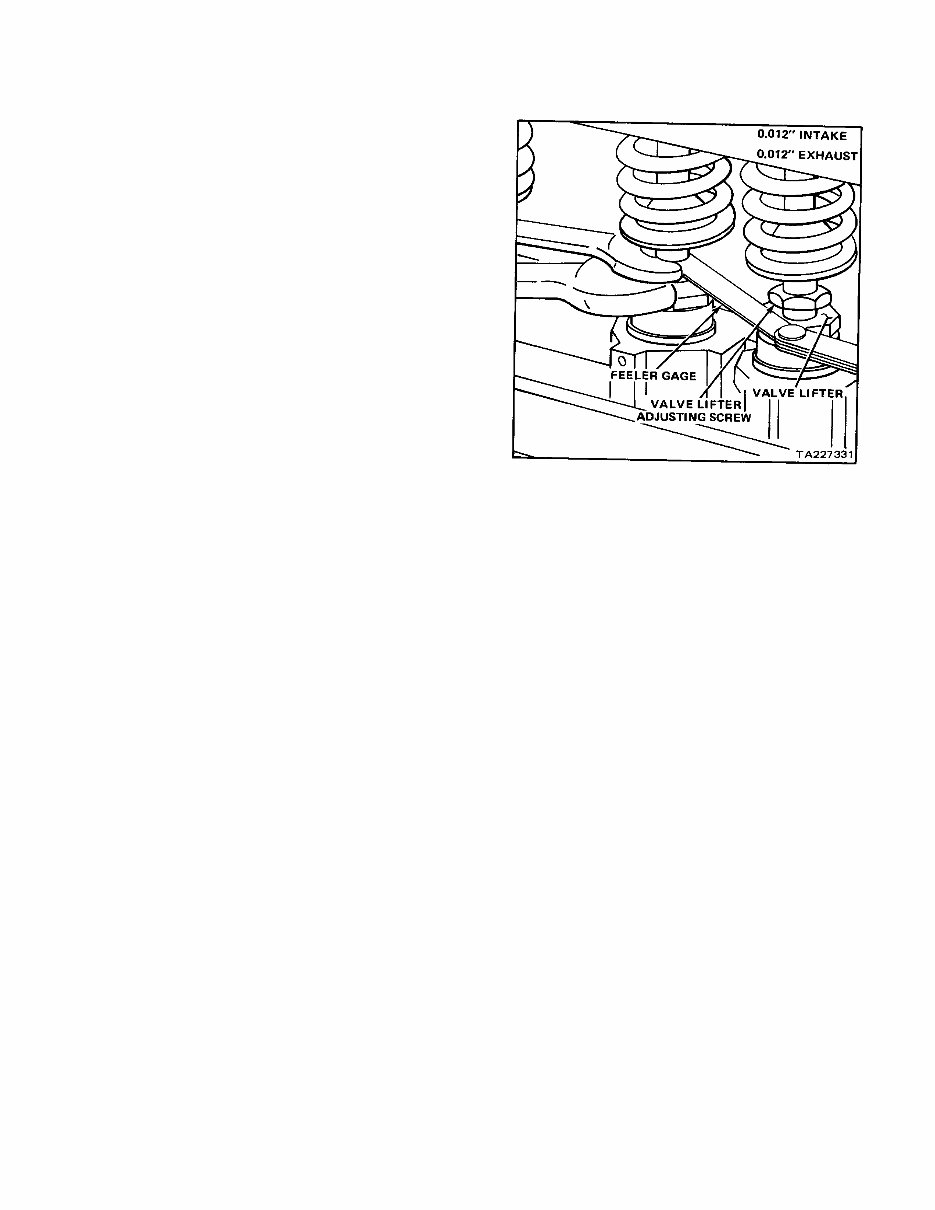
c. With the engine at operating temperature and
running at idle speed, set the valves for 0.012-inch
clearance as follows:
(1) Check for proper 0.012-inch clearance by
alternately passing a 0.01-inch and a 0.013inch
flat feeler gage between the head of the
adjusting screw and valve stem (fig. 28.1).
(2) If a 0.011-inch feeler gage moves freely back
and forth in the gap when the valve is not being
lifted and 0.013-inch feeler gage binds at all
times, the clearance requires no adjustment.
(3) If a 0.011-inch feeler gage is gripped at all times,
the clearance is insufficient.
(4) Hold valve lifter with an open end wrench while
using a second wrench to turn adjusting screw
one-quarter to one-half turn clockwise. Repeat
clearance check and adjustment until proper
clearance is obtained. The adjustable-type valve
lifters have self-locking adjusting screws that
require no locknuts.
(5) If 0.013-inch feeler moves freely when valve is
not being lifted, the clearance is too great. Hold
valve lifter with an open end wrench while using
a second wrench to turn valve lifter adjusting
screw counterclockwise one-quarter to one-half
turn. Repeat the clearance check and
adjustment until proper clearance is obtained.
(6) Repeat clearance check and adjustment for
remaining intake valves.
(7) Check exhaust valve clearance for proper 0.012-
inch clearance by alternately passing a 0.011-
and 0.013-inch flat feeler gage between the head
of the adjusting screw and the valve stem cap.
(8) If necessary, adjust the exhaust valve clearance
in the same manner as the intake valves
described in (1) through (5) above.
(9) Install the valve chamber cover using a new
gasket. Secure with two cover nuts and gaskets.
Figure 28.1. Value adjustment.
Page 27:
Paragraph 13.c. is changed to 13.d.
Paragraph 13.d.(3), change (TM 10-3930-237-20) to
paragraph 13.c.
Paragraph 13.d.(4), change (TM 10-3930-237-20) to
paragraph 11.o.
Page 28, paragraph 13.d.(5) and (6) change (TM 10-
3930-237-20) to paragraph 13.c.
WARNING
Compressed air, used for cleaning
purposes will not exceed 30 psi (207
kPa). Wear face shield and protective
clothing to prevent injury when using
compressed air.
Insert the above WARNING where indicated below:
Page 29, paragraph 15.b., after title and before (1).
Page 34, paragraph 16.b., after title and before (1).
Page 37, paragraph 20.c., after title and before (1).
Page 41, paragraph 21.c., after title and before (1).
Page 44, paragraph 23.b., after title and before (1).

TM 10-3930-237-35
C1
WARNING insertion continued:
Page 49, paragraph 27, after title and before a.
Page 47, paragraph 24.c.(8), first sentence, change of
cracks to for cracks.
Page 68, Figure 50, change callouts as follows:
21 Lockwasher 26 Cotter pin
22 Screw 27 Flat washer
23 Roller bearing 28 Shim
24 Steering knuckle 29 Setscrew
25 Nut 30 Nut
Page 72, paragraph 35.c.(2). Following the word arm
add (22), following nut (23) add torque to 40 - 50 inch-
pounds.
Page 77:
Paragraph 42.c., change title Cleaning and Inspection to
Cleaning, Inspection and Repair.
Paragraph 42.d (4), line 4, change on to an.
Page 94:
APPENDIX I REFERENCES is changed as follows:
Paragraph 1.
Line 2, change 320-5 to 310-25; following word
Terms add (Short Title)
Line 3 is superseded by:
310-50 Catalog of Abbreviations and Brevity Codes
Line 5 is deleted
Paragraph 2.
Line 7, change title to read:
Index of Army Motion Pictures and Related Audio
Visual Aids
Line 8, change title to read:
Index of Army Publications and Blank Forms
Lines 9, 10, 11 and 12 are deleted
After line 8 above add:
DA PAM 738-750, The Army Maintenance
Management System (TAMMS)
Paragraph 3.
Lines 14, 15 and 16 are deleted
Line 17, title is changed to read:
Military Symbols (Reprinted With Basic Incl C1)
After line 17 above add the following:
21-305, Manual For The Wheeled Vehicle Driver
Paragraph 4. Technical Manuals is deleted
Page 96, APPENDIX III
Line 2, change TM 10-3930-237-35P to TM 10-3930-
237-34P.
By Order of the Secretary of the Army
JOHN A. WICKHAM, JR.
General, United States Army
Chief of Staff
Official:
DONALD J. DELANDRO
Brigadier General, United States Army
The Adjutant General
Distribution:
To be distributed in accordance with DA Form 12-25A, Direct and General Support Maintenance requirements for
Warehouse Equipment.

TM 10-3930-237-35
TECHNICAL MANUAL HEADQUARTERS
DEPARTMENT OF THE ARMY
No. TM 10-3930-237-35 WASHINGTON, D.C., 24 September 1964
DS, GS, AND DEPOT MAINTENANCE MANUAL
TRUCK, LIFT, FORK, GASOLINE
SOLID RUBBER TIRED WHEELS
2000 POUND CAPACITY
ARMY MODEL MHE-192
CLARK MODEL C20B-1632032-100
FSN 3930-781-3857
CLARK MODEL C20B-1632033-127
FSN 3930-781-3858
Paragraph Page
CHAPTER 1. INTRODUCTION
Section I. General
Scope ............................................................................................................. 1 3
Appendixes ..................................................................................................... 2 3
Forms, records, and reports ........................................................................... 3 3
Orientation ...................................................................................................... 4 3
II. Description and Data
Description...................................................................................................... 5 3
Tabulated data................................................................................................ 6 4
CHAPTER 2. MAINTENANCE INSTRUCTIONS
Section I. Troubleshooting
Purpose .......................................................................................................... 7 6
Troubleshooting procedure............................................................................. 8 6
II. Engine
General ........................................................................................................... 9 9
Engine removal and replacement ................................................................... 10 9
Engine overhaul .............................................................................................. 11 12
Engine block ................................................................................................... 12 23
Valves ............................................................................................................. 13 24
III. Fuel System
General ........................................................................................................... 14 28
Carburetor ...................................................................................................... 15 28
Governor ......................................................................................................... 16 32
IV. Cooling System
General ........................................................................................................... 17 35
Radiator .......................................................................................................... 18 35
V. Electrical System
General ........................................................................................................... 19 36
Generator ....................................................................................................... 20 36
Starting motor ................................................................................................. 21 38
1
}

Paragraph Page
Section VI. Transmission and Drive System
General ........................................................................................................... 22 43
Transmission control lever and linkage .......................................................... 23 43
Transmission control valve ............................................................................. 24 44
Wheel and axle shaft ...................................................................................... 25 48
Drive wheel assembly..................................................................................... 26 49
Axle adapter and differential ........................................................................... 27 49
Transmission .................................................................................................. 28 51
VII. Steering System
General ........................................................................................................... 29 61
Steering gear .................................................................................................. 30 61
Steering axle................................................................................................... 31 66
Steering wheels .............................................................................................. 32 69
VIII. Brake System
General ........................................................................................................... 33 69
Hand brake mechanism ................................................................................. 34 70
Service brakes ................................................................................................ 35 71
Brake master cylinder ..................................................................................... 36 73
Wheel cylinder ................................................................................................ 37 74
Brake pedal and linkage ................................................................................. 38 75
IX. Seat
General ........................................................................................................... 39 76
Seat and backrest cushions ........................................................................... 40 76
X. Hydraulic System
General ........................................................................................................... 41 76
Hydraulic pump assembly .............................................................................. 42 76
Hydraulic control valve.................................................................................... 43 80
Tilt-lock valve .................................................................................................. 44 82
Control levers and linkage .............................................................................. 45 83
Hydraulic tilt cylinder....................................................................................... 46 84
Hydraulic lift cylinder....................................................................................... 47 86
Mast assembly................................................................................................ 48 88
Carriage assembly.......................................................................................... 49 91
APPENDIX I. REFERENCES ............................................................................................... -- 94
II. MAINTENANCE ALLOCATION CHART ........................................................ -- 95
III. REPAIR PARTS AND SPECIAL TOOLS LISTS ............................................ -- 96
2

CHAPTER 1
INTRODUCTION
Section I. GENERAL
1. Scope
a. This manual is published for use by personnel
responsible for direct and general support and depot
maintenance of the Fork Lift Truck, Models C26B-
1632032-100 and C20B1632033-127, manufactured by
Clark Equipment Company, Battle Creek, Michigan.
b. The direct reporting by the individual user of
errors, omissions, and recommendations for improving
this manual is authorized and encouraged. DA Form
2028 (Recommended changes to DA Publications) will
be used for reporting these improvements. This form will
be completed in triplicate using pencil, pen or typewriter.
The original and one copy will be forwarded direct to the
Commanding Officer, U. S. Army Mobility Equipment
Center, ATTN: SMOME-MM, 4300 Goodfellow Blvd., St.
Louis, Mo., 63120. One information copy will be
provided to the individual’s immediate supervisor (e.g.,
officer, noncommissioned officer, supervisor, etc.).
2. Appendixes
Appendix I is a list of current references applicable to this
manual. Appendix II, containing the Maintenance
Allocation Chart, is published in the Organizational
Maintenance Manual, TM 10-3930-237-20. Appendix III,
repair parts and special tools lists authorized for field and
depot maintenance, is published in the Field and Depot
Maintenance Repair Parts and Special Tools Lists
Manual, TM 10-3930-23735P.
3. Forms, Records, and Reports
The maintenance forms, records, and reports to be used
in the direct support, general support and depot
maintenance of this equipment are listed and described
in TM 38-750.
4. Orientation
Throughout this manual, the terms right, left, front and
rear, with respect to the engine or truck, indicate
directions from the viewpoint of the operator sitting in the
seat of the truck.
Section II. DESCRIPTION AND DATA
5. Description
a. Engine. The four-cylinder, four-stroke cycle,
L-head, water-cooled engine has a 3¼ inch bore and a
3½ inch stroke for a displacement of 116 cubic inches. It
develops a brake horsepower of 34.2 at 2800 rpm and
has a compression ratio of 6.72 to 1. The crankshaft has
three main bearings, and the engine is pressure
lubricated by positive-displacement gear pump.
b. Drive System. The unitized drive system
consists of a single-speed, forward and reverse
transmission; a differential with a pinion shaft directly
driven by transmission output; and pinion shafts which
engage the differential and transfer power to the front
wheels to propel the vehicle. Final reduction is in the
wheels.
c. Hydraulic System. The hydraulic system is
powered by a vane-type hydraulic pump mounted on and
driven by the engine. The pump capacity is 6 gpm at
1200 rpm. The working pressure of the hydraulic system
is 2000 psi maximum.
d. Steering System. The fork lift truck is steered by
the rear wheels through the use of a mechanical steering
3

system. The steering system consists of a steering
handwheel, steering gear, drag link assembly, steering
axle and tie rods.
e. Electrical System. The negatively grounded, 12-
volt electrical system employs a DC generator with a
conventional three-unit voltage regulator. The starting
circuit is actuated by the starter and ignition switch. The
starting circuit is routed through the transmission neutral
position switch to prevent cranking of the engine when
the transmission is in either drive position. By closing the
circuit through the ignition switch and neutral position
switch, the starting relay is energized which completes
the circuit to the starter motor solenoid switch. As the
solenoid energizes, it engages the overrunning clutch
with the flywheel ring gear and completes the circuit from
the battery to crank the engine.
f. Differences in Models. The two models covered
in this manual differ in the height of the mast assembly
and the addition of overhead protection for the driver in
model with the higher mast assembly. Model C20B-
1632032-100 has a 100 inch lifting capability while Model
C20B-1632033-127 has a 127 inch lifting capability and
is provided with a drivers overhead guard. General
configuration of mast assembly parts is the same; only
dimensions are different.
6. Tabulated Data
a. Engine.
Make ........................................... Continental
Model .......................................... YS 116
Number of cylinders- .................. Four
Bore ............................................ 3¼ inches
Stroke ......................................... 3½ inches
Displacement .............................. 116 cubic inches
Compression ratio ..................... 6.72 to 1
Brake horsepower ...................... 34.2 at 2800 rpm
Torque ........................................ 89 ft lb at 1200 rpm
Firing order ................................ 1-3-4-2
Weight, bare engine .................. 279 lb.
Number of main bearings ........... Three
Crankshaft:
Main bearing journal 1.7482 in. min.
diameter.
Connecting rod 1.4338 in. min.
journal diameter.
Clearance-main 0.002 in. to 0.0032 in.
bearing journals to
bearings.
End play ............................... 0.002 in. to 0.006 in.
Clearance -crank pin 0.0007 in. to 0.0031 in.
bearing journals to
connecting rod
bearings.
Flywheel:
Runout ................................. 0.008 in. max.
Eccentricity .......................... 0.008 in. max.
Flywheel housing:
Face runout ......................... 0.008 in. max.
Bore eccentricity .................. 0.008 in. max.
Camshaft:
Fan end bearing 1.8075 in. min.
journal diameter.
Middle bearing 1.7445 in. min.
journal diameter.
Drive end bearing 1.2455 in. min.
journal diameter.
Clearance-camshaft 0.002 in. to 0.004 in.
journals to fan end
and drive end
bearings.
Clearance-camshaft 0.003 in. to 0.0047 in.
journal to center
bearing.
End play............................... 0.003 in. to 0.007 in.
Clearance-camshaft 0.0015 in. max.
gear to crankshaft
gear.
Valves:
Intake valve stem 0.3128 in. max.
diameter.
Exhaust valve stem 0.3128 in. max.
diameter.
Valve guide bore 0.3133 in. max.
diameter-intake.
Valve guide bore 0.3150 in. max.
diameter -exhaust.
Valve spring tension:
Compressed to 42 pounds min.
1
3
6
3
4
in.
Compressed to 86 pounds min.
1
1
6
5
4
in.
Clearance-valve 0.005 in. max.
lifter to bore.
Valve seat angle .................. 45°
Pistons:
Piston pin hole 0.8796 in. max.
diameter.
Piston ring gap..................... 0.010 in. min. to 0.020
in. max.
Piston pin diameter ............. 0.8588 in. min.
Piston ring groove
width:
Top groove................. 0.099 in. max.
Middle grooves .................... 0.0985 in. max.
Bottom groove ..................... 0.191 in. max.
Piston ring width:
Top ring ............................... 0.0910 in. min.
Middle ring ........................... 0.0910 in. min.
Bottom ring- ......................... 0.1840 in. min.
4
You're Reading a Preview
What's Included?
Fast Download Speeds
Online & Offline Access
Access PDF Contents & Bookmarks
Full Search Facility
Print one or all pages of your manual
$31.99
Viewed 22 Times Today


Secure transaction
What's Included?
Fast Download Speeds
Online & Offline Access
Access PDF Contents & Bookmarks
Full Search Facility
Print one or all pages of your manual
$31.99
These digital manuals are available in .PDF format, making them compatible with all versions of Windows, Mac, and Linux operating systems. They are printable and can be accessed instantly at high speed. The only requirement is Adobe Reader.


