

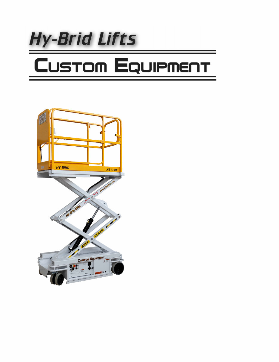
Hy-Brid Custom lift,HB1030,HB1430 manual
What's Included?
Fast Download Speeds
Online & Offline Access
Access PDF Contents & Bookmarks
Full Search Facility
Print one or all pages of your manual
OPERATION,
SAFETY, AND
MAINTENANCE
MANUAL
Hy-Brid Scissors Lift
Models
HB 1030
HB 1430
Self-Propelled
Aerial Work Platform
1
Foreword
The purpose of this Operations and Safety Manual is to provide users with the instructions and operating
procedures essential to properly and safely operate the Custom Equipment Hy-Brid Lift for its intended purpose,
to position personnel and their necessary tools and materials.
DANGER
THE OPERATION AND SAFETY MANUAL
MUST BE READ AND UNDERSTOOD PRIOR
TO OPERATING THE MACHINE.
THE USER/OPERATOR SHOULD NOT ACCEPT OPERATING RESPONSIBILITY UNTIL THE MANUAL HAS
BEEN READ AND UNDERSTOOD AS WELL AS HAVING OPERATED THE LIFT UNDER SUPERVISION OF
AN EXPERIENCED AND QUALIFIED OPERATOR.
BECAUSE THE MANUFACTURER HAS NO DIRECT CONTROL OVER MACHINE APPLICATION AND
OPERATION, PROPER SAFETY PRACTICES ARE THE RESPONSIBILITY OF THE USER AND ALL
OPERATING PERSONNEL.
WARNING
ANY MODIFICATION ON THIS MACHINE
WITHOUT THE EXPRESS WRITTEN CONSENT
OF THE MANUFACTURER IS PROHIBITED.
If there is a question on application and/or operation, contact:
Custom Equipment, Inc.
2647 Hwy 175
Richfield, WI 53076
USA
Phone: 262-644-1300
Fax: 262-644-1320
SUPO-602 Revisions
Rev 09: 4/24/09: Decal Location (DE603)
Rev 10:6/22/09: Curved Railing, Slide Lock Rev (cover, p. 7, 12)
2
Lanyard Attachment
Point
Table of Contents
PRODUCT DESCRIPTION ..................................................................................................................................................... 3
PURPOSE .................................................................................................................................................................................. 3
MACHINE SPECIFICATIONS .................................................................................................................................................... 3
SAFETY ..................................................................................................................................................................................... 4
SAFETY SYMBOLS ................................................................................................................................................................... 4
GENERAL RULES AND PRECAUTIONS ..................................................................................................................................... 4
SAFETY FEATURES .................................................................................................................................................................. 6
SAFETY AND CONTROL DECAL LOCATIONS .......................................................................................................................... 7
OPERATION ............................................................................................................................................................................. 9
UPPER CONTROLS ................................................................................................................................................................. 10
PRE-START INSPECTION ....................................................................................................................................................... 11
DRIVING AND STEERING ....................................................................................................................................................... 11
BRAKING ............................................................................................................................................................................... 12
ELEVATING AND LOWERING THE PLATFORM ..................................................................................................................... 12
EXTENDING THE SLIDE-OUT DECK...................................................................................................................................... 12
SHUTDOWN PROCEDURE ...................................................................................................................................................... 13
EMERGENCY LOWERING ...................................................................................................................................................... 14
MAINTENANCE..................................................................................................................................................................... 15
INSPECTION AND REGULAR MAINTENANCE CHECKLISTS .................................................................................................. 15
LUBRICATION ........................................................................................................................................................................ 19
TROUBLESHOOTING.............................................................................................................................................................. 19
REPLACEMENT PARTS .......................................................................................................................................................... 21
WARRANTY ........................................................................................................................................................................... 26
Fall Protection Notice
The guardrail system around the perimeter of the platform is the fall protection system for self-propelled
elevating work platforms per the American National Standards Institute ANSI/SIA A92.6 Standard. It is
prohibited to use an Aerial Work Platform manufactured by Custom Equipment, Inc. with any portion, or all, of
the guardrails removed.
Lanyard anchorage points on this type of equipment are not required to conform to the applicable ANSI/SIA
Standard. However, if anchorage points for lanyard attachments are required by site authorities, or other
regulations, the anchorage points on all equipment manufactured by Custom Equipment, Inc. are recommended
to be used for work positioning restraints of personnel only. Lanyard lengths are to be determined by
operator/owner to restrict the operator to the confines within the guardrail system.
WARNING
USE OF FALL ARREST SYSTEMS ATTACHED
TO ANCHORAGE POINTS ON EQUIPMENT
MAY CAUSE MACHINE TO TIP, RESULTING IN
SERIOUS INJURY OR DEATH.

3
Product Description
Purpose
Custom Equipment's Hy-Brid Scissors Lift is an aerial work platform designed for compact size, ease of operation,
and operator safety. The purpose of the machine is to position personnel and their necessary tools and materials.
Machine Specifications (Subject to Change)
HB1030 HB1430
DIMENSIONS
Working Height (maximum) 16 ft. 4.87 m 20 ft. 6.1 m
Platform Height (maximum) 10 ft. 3 m 14 ft. 4.26 m
Stowed Height 66.88 in. 1.7 m 71 in. 2.16 m
Ground Clearance (Pothole Guard Stowed) 2 in. 5.08 cm 2.75 in. 7 cm
Ground Clearance (Pothole Guard Engaged) 0.75 in. 1.9 cm 0.75 in. 1.9 cm
Overall Width 30 in 0.76 m 30 in 0.76 m
Overall Length 63.5 in. 1.61 m 63.5 in. 1.61 m
Platform (Retracted, Inside) 25 in. x 60 in. 0.64 mx1.52 m 25 in. x 60 in. 0.64 mx1.52 m
Slide-Out Deck Length 30 in. 0.76m 30 in. 0.76m
Guard Rail Height 42 in. 1 m 42 in. 1 m
Toe Board Height 4 in. .1 m 4 in. .1 m
Platform Entrance 21 in. 0.53 m 25 in. 0.3 m
Step Height NA NA 12 in. 0.3 m
Wheel Base 51 in. 1.3 m 51 in. 1.3 m
Wheel Track 23.63 in. 0.6 m 23.63 in. 0.6 m
Turning Radius (Inside) 21 in. 0.53 m 21 in. 0.53 m
Tire Size (Solid, Non-Marking)-Front 8 in. 20.3 cm 10 in. 25.4 cm
Tire Size (Solid, Non-Marking)-Rear 10 in. 25.4 cm 10 in. 25.4 cm
RATED LOAD
Lift Capacity (Evenly Distributed): 750 lbs. 340.2 kg 670 lb. 304 kg.
Slide-Out Deck Capacity 250 lbs 113.4 kg 250 lb. 113.4 kg.
Horizontal/Manual Force 112.5 lb. 500 N 100.5 lb. 447 N
FLOOR LOADING
Machine Weight (Unloaded) (Approx.) 1275 lb. 578.kg 1650 lb. 748.4 kg
Minimum Wheel Load 62.2 psi 428.58 kPa 80.5 psi 555 kPa
Maximum Wheel Load 98.8 psi 680.2 kPa 113.2 psi 780.5 kPa
Minimum Machine Loading 96.37 psf 4.61 kPa 124.5 psf 5.96 kPa
Maximum Machine Loading 153.06 psf 7.33 kPa 175 psf 8.38 kPa
ENVIRONMENTAL LIMITATIONS
Wind No Windy Conditions/Indoor Use Only ( C ) No Windy Conditions/Indoor Use Only ( C )
Rated Slope Level Surface Level Surface
Tilt Sensor Activated 2° 2° 2° 2°
Gradeability 30% 30% 30% 30%
Temperature -4° F-104° F -20° C-40° C -4° F-104° F -20° C-40° C
Vibration 8.2 ft/s2 max 2.5 m/s2 max 8.2 ft/s2 max 2.5 m/s2 max
POWER SYSTEMS
Drive System (Proportional Electric):
Drive Speed (Platform Elevated) 0-0.7 mph 0-.31 m/s 0-0.7 mph 0-.31 m/s
Drive Speed (Platform Lowered) 0-2mph 0-.89 m/s 0-2mph 0-.89 m/s
Lift/Lower Speed 15/22 sec 15/22 sec 21/31 sec 21/31 sec
Hydraulic Pressure (max) 1300 psi 8963 kPa 2000 psi 13 790 kPa
Hydraulic Fluid Capacity 1.325 gal 5.38 L 1.325 gal 5.38 L
Power System-Voltage 24V DC 24V DC 24V DC 24V DC
Batteries-Deep Cycle Marine (2) 12V (2) 12V (2) 12V (2) 12V
4
Safety
Safety Symbols
Warnings and instructions that have a direct impact on safety are identified with the following signals:
"DANGER" indicates an imminently hazardous situation,
which, if not avoided, will result in death or serious injury.
"WARNING" indicates a potentially hazardous situation,
which, if not avoided, could result in death or serious injury.
"CAUTION" indicates a potentially hazardous situation
which, if not avoided, could result in minor or moderate
injury or damage to equipment.
General Rules and Precautions
Custom Equipment, Inc. designed the Hy-Brid Lift self-propelled scissor lift to be safe and reliable. It is intended
for elevating personnel, along with their necessary tools and materials to overhead work locations.
An operator of any type of work platform is subject to certain hazards that cannot be protected by
mechanical means. It is therefore essential that operators be competent, careful, physically and mentally
fit and thoroughly trained in safe operation of this machine.
Although Custom Equipment, Inc. conforms to specified ANSI & OSHA requirements, it is the
responsibility of the owner to instruct operators with the safety requirements made not only by Custom
Equipment, Inc., but by the various safety boards in your area, as well as additional requirements set
forth by ANSI & OSHA. If you come across a situation that you think might be unsafe, stop the platform
and request further information from qualified sources before proceeding.
WARNING
NEVER REACH BETWEEN SCISSORS LINKS
OR PROP UP PLATFORM.
DANGER
FAILURE TO FOLLOW THIS WARNING
WILL CAUSE DEATH OR PERSONAL INJURY.
WARNING
FAILURE TO FOLLOW THIS WARNING MAY
CAUSE DEATH OR PERSONAL INJURY.
CAUTION
FAILURE TO FOLLOW THIS WARNING
MAY CAUSE INJURY OR DAMAGE EQUIPMENT.

5
Only qualified operators may operate this unit.
All operators must read and understand the Operation and Safety Manual. They must understand all
decals and warning labels on unit.
ANSI A92.6 and other applicable standards identify requirements of all parties who may be involved with
self-propelling elevating work platforms. Owner/user/operator must be familiar with Sections 6, 7, 8, 9,
and 10, which contain responsibilities of the owner, users, operators, lessors, and lessees including
safety, training, inspection, maintenance and operation. A copy of the ANSI Standard is considered part
of this machine.
Do not work on platform if your physical condition is such that you feel dizzy or unsteady in any way.
Do not neglect/misuse machine. Report any misuse of equipment to proper personnel.
Prevent unauthorized use; when unit is not in use, remove key.
It is recommended all personnel on unit wear headgear (hard hats).
Use machine only for purposes for which it was intended.
Lift should never be used as a crane.
Never use unit as electrical grounds for arc welding.
Do not override any hydraulic, mechanical, or electrical safety devices.
Check job site for unsafe working conditions.
Unit must be on hard level surface before elevating. Do not operate on incline or uneven surface.
Do not use outdoors in windy conditions or electrical storms.
DANGER
DO NOT OPERATE MACHINE NEAR POWER
LINES. THE PLATFORM AND ENCLOSURES
ARE NOT INSULATED.
You must maintain a clearance of at least 10 feet between any part of the machine, or its load, and any
electrical line or apparatus carrying over 300 volts up to 50000 volts. One-foot additional clearance is
required for each additional 30,000 volts.
Watch out for others. Keep others clear of operating platform. Never allow others to pass under a raised
platform or position the platform over someone.
Equipment is only as safe as the operator.
Do not enter or exit platform while machine is in motion.
Never mount or dismount a raised platform.
Make sure entry gate is secured before operating machine from the platform.
Never belt or tie off to an adjacent structure.
Do not exceed the load capabilities of the platform.
Distribute load evenly over platform floor area.
Secure tools and materials.
Do not use ladders or scaffolding on the platform to obtain greater height.
Personnel must maintain a firm footing on the platform floor and work only within the platform area.
It is recommended to avoid sudden braking or steering. Go slowly and leave more maneuvering room
during cold weather operation.
Before operation, ensure that the machine is properly serviced.
Do not use machine if it is not working properly.
Make sure platform rails and pins are secured.
Operator shall use the maintenance lock when performing all types of maintenance procedures.
Do not smoke while charging the battery.
6
Safety Features
Emergency Stop. This lift is equipped with two emergency stop switches, one at the platform control and one at the
base control, that when activated, will render the unit inoperable until reset. To reset, pull the button out.
Automatic Parking Brake.
Free Descent Protection. A velocity fuse is installed in the hydraulic circuit to prevent the platform from descending
in case of a ruptured hydraulic hose. The platform will be hydraulically locked whenever this velocity fuse activates.
Emergency Manual Override. This machine is equipped with a manual override valve. When opened, the platform
will descend.
Tilt Alarm. An audible alarm sounds when the machine is tilted. Drive and elevate functions are disabled when the
tilt sensor is disconnected. For some models, drive and elevate functions are disabled when tilted.
Puncture-proof Wheels.
Guardrails and Kick Plates (42”/4”).
Non-slip Deck.
Key Switch Security.
Decals. Danger, Caution, and Warning decals are displayed at various locations on this unit. These decals are to
conform to ANSI-SIA A92.3-1990 standards as interpreted by Custom Equipment, Inc.
Entrance Gate.
Pothole Protection.
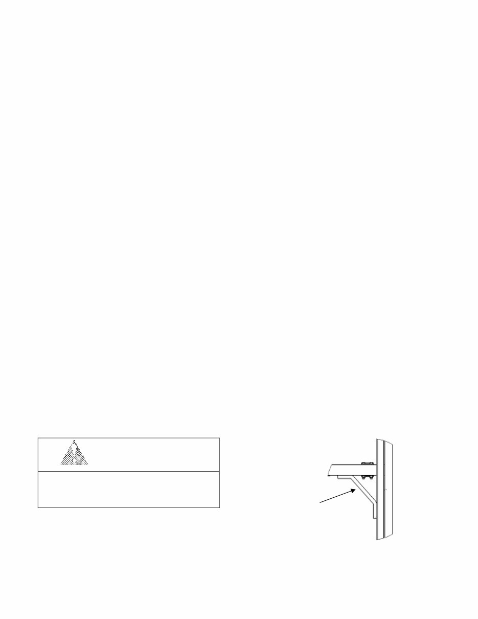
Maintenance Lock. The maintenance lock must be placed into position whenever the machine is being serviced in
the raised or partially raised position. Serious injury and/or death could result if maintenance lock is not used
properly.
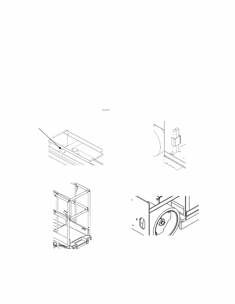
Figure 4: Pothole Protection
Figure 2: Maintenance Lock Storage
Insert Pins into
Holes in Roller
Track
Figure 1: Maintenance Lock Use
Figure 3: Entry Gate
7
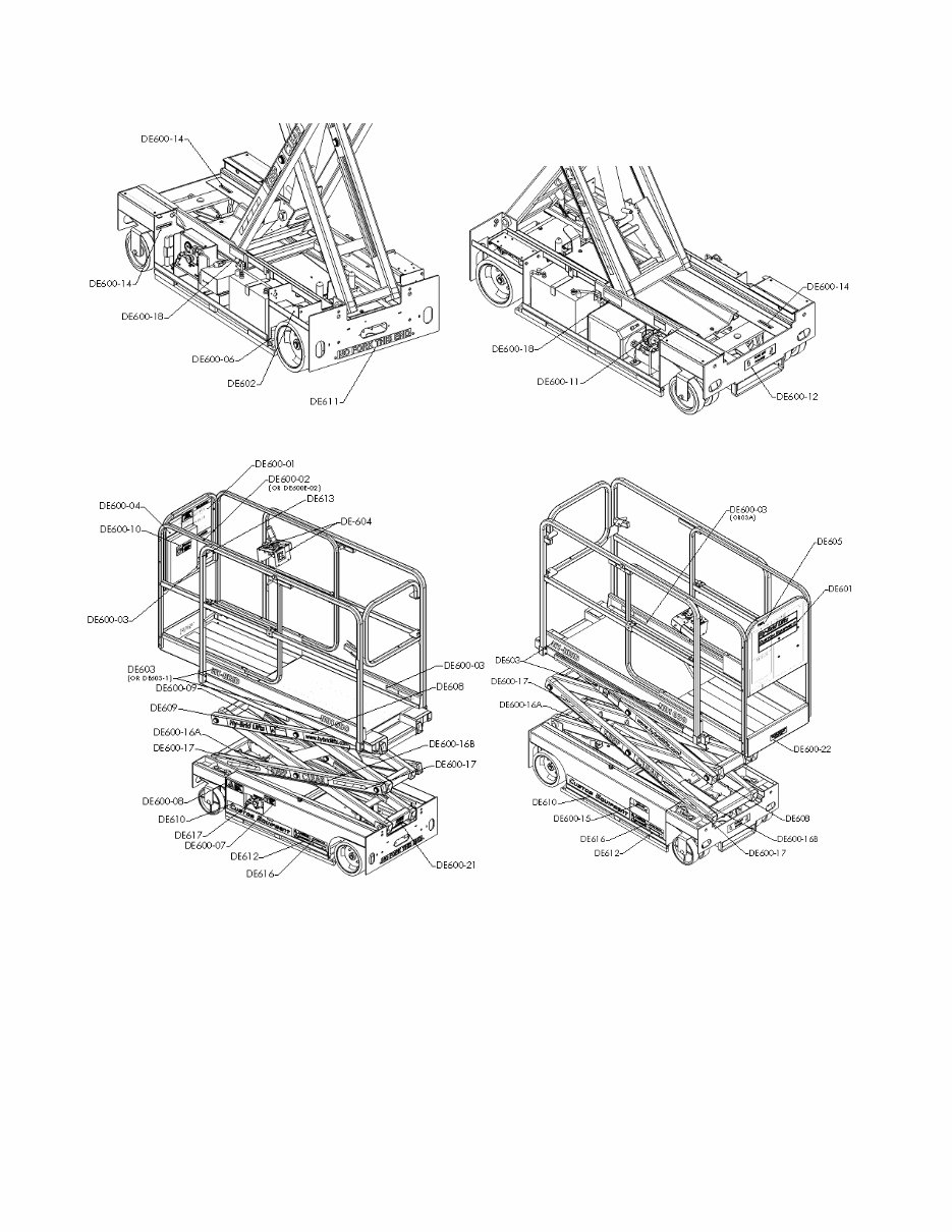
Safety and Control Decal Locations

8
PART # DESCRIPTION QTY.
DE600-01 WARNING-INSPECT 1
DE600-02 or DE600E-02 DANGER-IMPROPER USE DECAL 1
DE600-03 or DE600-3A MAX CAPACITY DECAL 3
DE600-04 PLAT EXT & GATE DECAL 1
DE600-05 DANGER TIP DECAL 1
DE600-06 REPLACE OEM ONLY DECAL 2
DE600-07 DO NOT POWERWASH DECAL 1
DE600-08 WARNING BATTERY GAS DECAL 1
DE600-09 ELECTROCUTION HAZARD DECAL 2
DE600-10 WARNING-IMPROPER USE DECAL 1
DE600-11 E-DOWN TURN BRASS DECAL 1
DE600-12 FORK POCKET DECAL 1
DE600-14 MAINT LOCK PIN DECAL 3
DE600-15 E-DOWN LOCATION DECAL 1
DE600-16A KEEP CLEAR DECAL (KEEP) 2 or 4
DE600-16B KEEP CLEAR DECAL (CLEAR) 2 or 4
DE600-17 SAFETY STRIPE 2 or 4
DE600-18 BATTERY WEIGHT DECAL 2
DE600-19 LOWER CONTROL DECAL 1
DE600-21 BRAKE RELEASE DECAL 1
DE-601 NAME LOGO DECAL 1
DE602 OR DE602-1
SERIAL NUMBER PLATE
(OR DE602C OR DE602-1C)
1
DE603 OR DE603-1
MODEL NUMBER DECAL
(FOR SOME MODELS, ALSO DE603C, DE603J)
2
DE-604 JOYSTICK DECAL (2 PIECES) 1
DE605 OR DE605-1
SMALL SERIAL NO. REFERENCE
(OR DE605C OR DE605-1C)
1
DE608 WWW.HYBRIDLIFTS.COM 2
DE609 HY-BRID LIFTS 2
DE610 LOWER CUSTOM EQUIPMENT LOGO 2
DE611 NO FORK DECAL 1
DE612 PH WARNING DECAL 2
DE613 LANYARD ATTACHMENT POINT DECAL 1
DE616
NO FORK DECAL
(NOT ON ALL MODELS)
2
DE617 CHARGER CORD LOCATION DECAL 1
9
Operation
Preliminary Unpacking Instructions and Dealer Inspection
Maintenance locks must be engaged prior to inspecting or servicing the unit when the platform is extended.
Inspect machine for any possible damage during shipment; perform a pre-delivery inspection. Reset emergency
stop switches, if necessary.
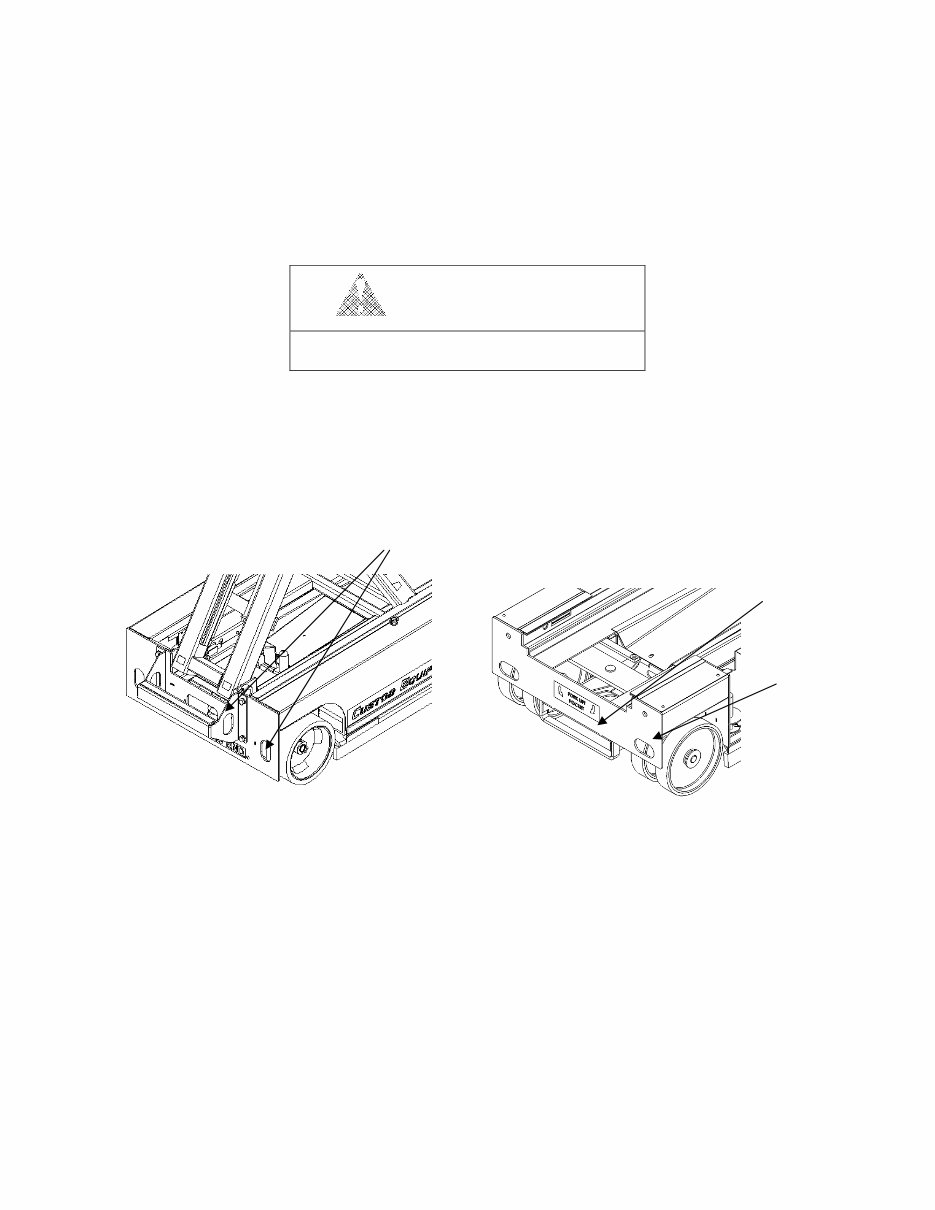
Loading and Unloading Procedures
WARNING
DO NOT OVER-TIGHTEN LOAD BINDERS
WHEN SECURING LOAD FOR TRANSPORT
TIE DOWN WARNING – Do not over-tighten load binders when securing load for transport. Damage will
occur due to the design intent of this product.
A forklift pocket and tie down/lift points are provided for loading and unloading and for securing the machine on a
trailer or truck bed. Do not use forklift from back of machine.
Forklift
Figure 7: Forklift Pocket, Front
Tie Down/Lift Points
Tie Down/
Lift Points
Tie Down/
Lift Points
Figure 6: Back Tie Down/Lift Points
You're Reading a Preview
What's Included?
Fast Download Speeds
Online & Offline Access
Access PDF Contents & Bookmarks
Full Search Facility
Print one or all pages of your manual
$30.99
Viewed 81 Times Today


Secure transaction
What's Included?
Fast Download Speeds
Online & Offline Access
Access PDF Contents & Bookmarks
Full Search Facility
Print one or all pages of your manual
$30.99
The Hy-Brid Custom lift operation, safety, and maintenance manual is an essential resource for professional mechanics and DIY enthusiasts. This manual provides comprehensive guidance for the HB1030 and HB1430 self-propelled aerial work platforms (scissor lifts). It covers crucial information on the operation, safety protocols, and maintenance procedures, ensuring that users can effectively and safely utilize these equipment. Whether you are a seasoned professional or a hands-on DIY enthusiast, this manual equips you with the necessary knowledge to maintain and operate the HB1030 and HB1430 aerial work platforms.


