

OPERATION/MAINTENANCE
AND
ILLUSTRATED PARTS MANUAL
FOR
CALAVAR SELF-PROPELLED CONDOR
MODELS 3238, 4046, 4248,
4248E, 5056, 6066
Calavar Corporation provides this Manual for the guidance of all
owners, operators, and servicing personnel in order to obtain the
longest possible trouble-free service. It contains general data;
specifications; operating instructions; recommended lubrication
procedures; vendor information and specifications; illustrated
parts breakdown and a special section on safety.
IIMAL.MVII111
CORPORATION
Model
Serial No.
Date Delivered
CUSTOMER
Note: . Additional copies of this Manual (Part No. 92151) may be
obtained through the Parts Department at Calavar.
Series V (Serial Nos. 2545-3170)
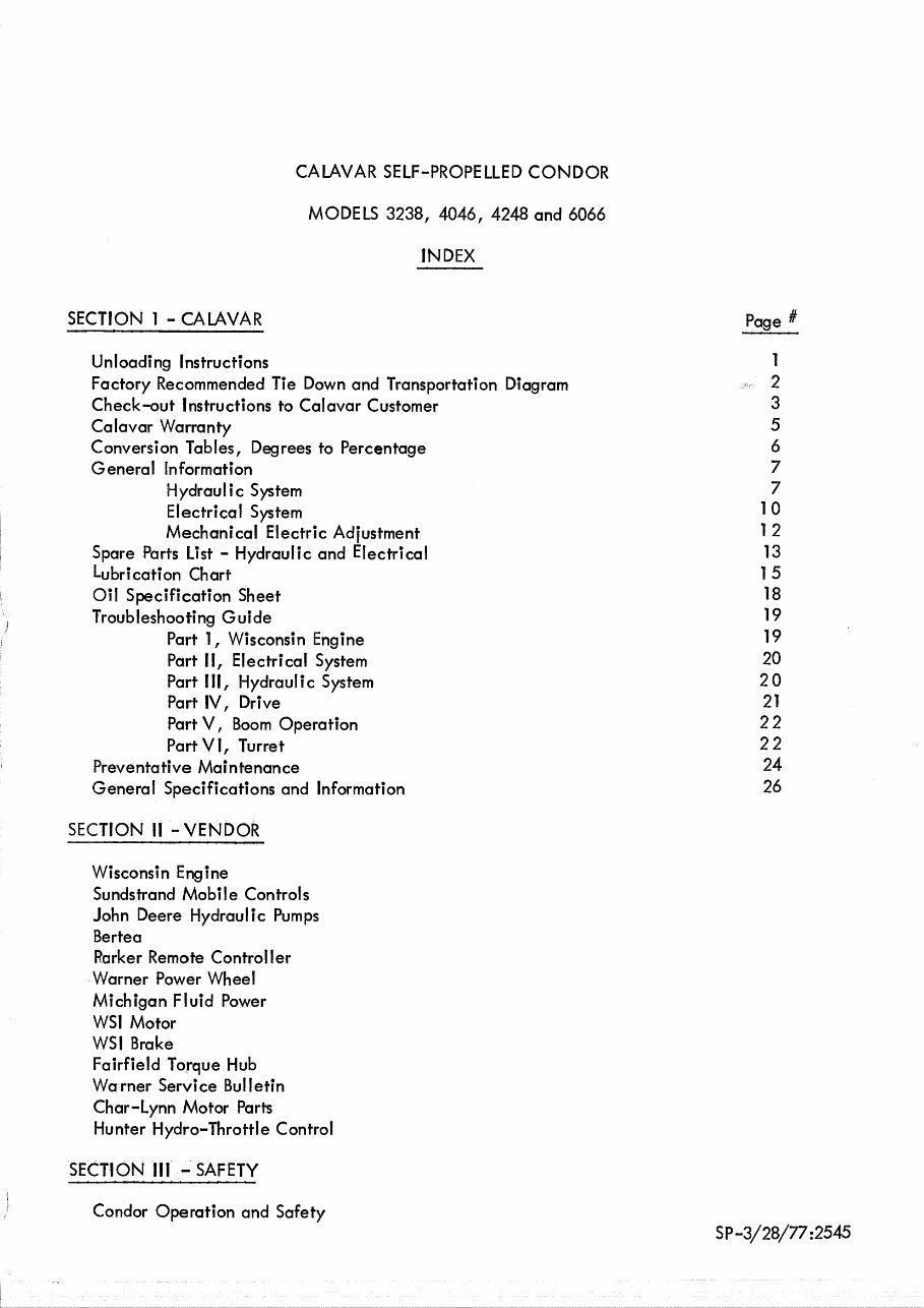
CALAVAR SELF-PROPELLED CONDOR
MODELS 3238, 4046, 4248 and 6066
INDEX
SECTION 1 - CALAVAR
Page #
Unloading Instructions
1
Factory Recommended Tie Down and Transportation Diagram
2
Check-out Instructions to Calavar Customer
3
Calavar Warranty
5
Conversion Tables, Degrees to Percentage 6
General Information 7
Hydraulic System
7
Electrical System
10
Mechanical Electric Adjustment
12
Spare Parts List - Hydraulic and Electrical
13
Lubrication Chart 15
Oil Specification Sheet 18
Troubleshooting Guide
19
Part 1, Wisconsin Engine
19
Part II, Electrical System
20
Part III, Hydraulic System
20
Part IV, Drive 21
Part V, Boom Operation
22
Part VI, Turret
22
Preventative Maintenance
24
General Specifications and Information
26
SECTION II - VENDOR
Wisconsin Engine
Sundstrand Mobile Controls
John Deere Hydraulic Pumps
Bertea
Parker Remote Controller
Warner Power Wheel
Michigan Fluid Power
WSI Motor
WSI Brake
Fairfield Torque Hub
Warner Service Bulletin
Char-Lynn Motor Parts
Hunter Hydro-Throttle Control
SECTION III - SAFETY
Condor Operation and Safety
SP-3/28/77:2545
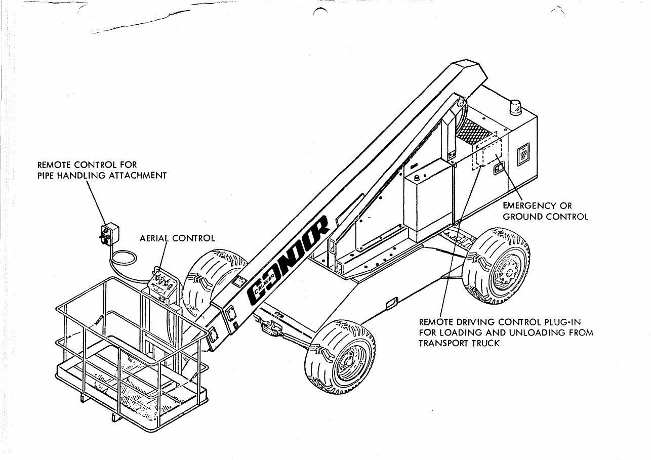
EMERGENCY OR
GROUND CONTROL
AERIAL CONTROL
REMOTE CONTROL FOR
PIPE HANDLING ATTACHMENT
REMOTE DRIVING CONTROL PLUG-IN
FOR LOADING AND UNLOADING FROM
TRANSPORT TRUCK
SELF-PROPELLED CONDOR
PARTS AND MAINTENANCE MANUAL
INTRODUCTION
The function of the Parts and Maintenance Manual is to first provide the Customer
with a complete and up-to-date Parts Manual covering all models presently in pro-
duction and second, to aid in ordering the correct parts. If used properly, it will
provide the customer with a source of information that will aid in solving quickly
and inexpensively the bulk of maintenance problems.
Under the various sections called out in the index, Calavar has included all the
specification sheets from the manufacturers of component parts that make up the
Condor, as well as a general trouble shooting guide directed solely to the Condor
as a completed unit.
Throughout this manual reference is made to unit serial numbers, and the use of
this number when ordering parts will assist our parts department in giving you prompt
and accurate service. The use of correct serial numbers and part numbers will also
expedite completion of warranty claims sent to Calavar. Serial numbers should
also be used at all times in phone conversations to Calavar's service personnel.
This manual has been produced as a valuable tool for our customers. It is in your
best interest that time be spent to read and understand all the sections in this
manual.
Calavar has included a special section that deals with the safe operation of the
self-propelled Condor, as well as information about certain items that must be
inspected periodically to ensure a safe operating unit.
8/25/78
S P2545
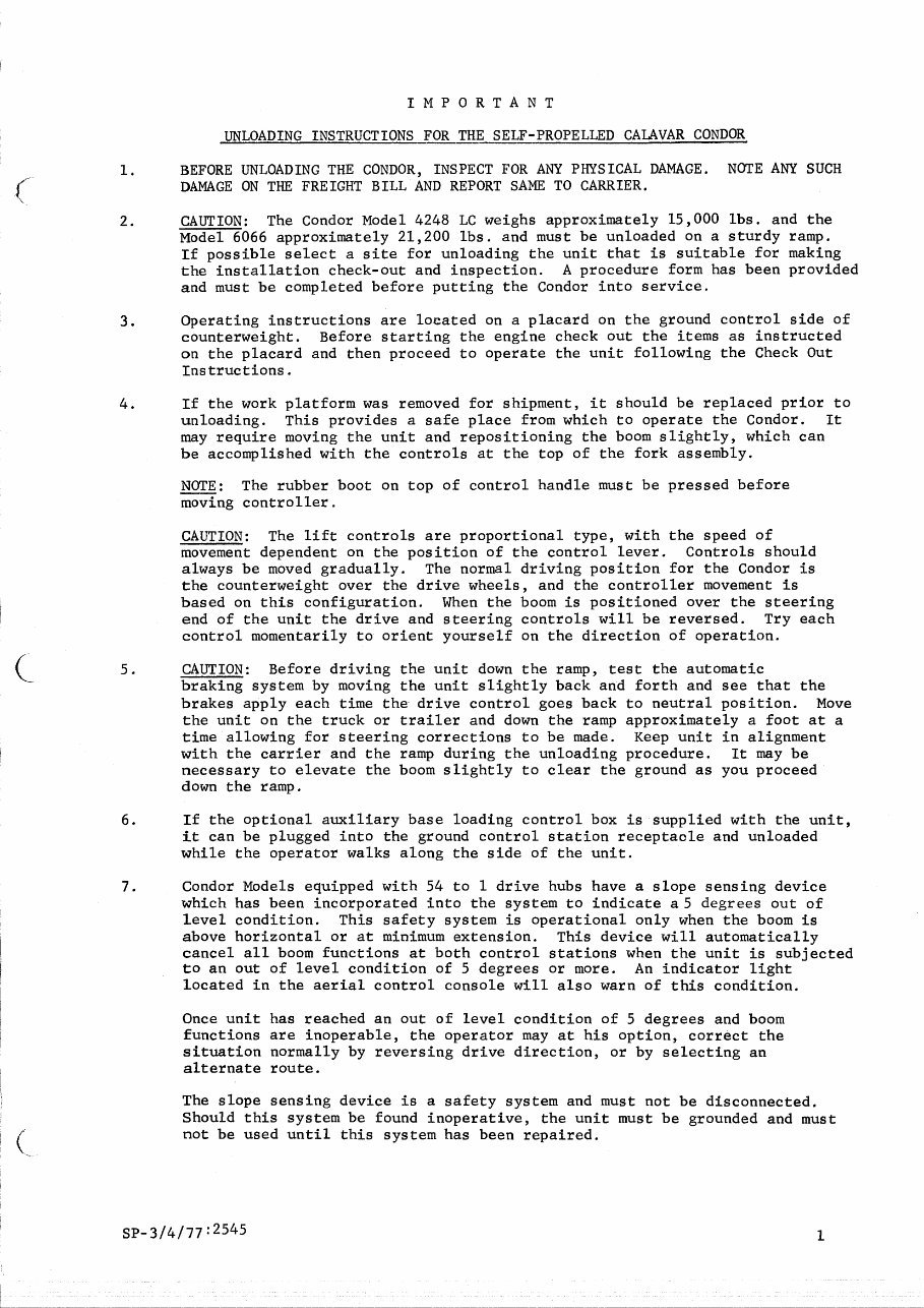
IMPORTANT
UNLOADING INSTRUCTIONS FOR THE SELF-PROPELLED CALAVAR CONDOR
1. BEFORE UNLOADING THE CONDOR, INSPECT FOR ANY PHYSICAL DAMAGE. NOTE ANY SUCH
DAMAGE ON THE FREIGHT BILL AND REPORT SAME TO CARRIER.
2.
CAUTION: The Condor Model 4248 LC weighs approximately 15,000 lbs. and the
Model 6066 approximately 21,200 lbs. and must be unloaded on a sturdy ramp.
If possible select a site for unloading the unit that is suitable for making
the installation check-out and inspection. A procedure form has been provided
and must be completed before putting the Condor into service.
3.
Operating instructions are located on a placard on the ground control side of
counterweight. Before starting the engine check out the items as instructed
on the placard and then proceed to operate the unit following the Check Out
Instructions.
4. If the work platform was removed for shipment, it should be replaced prior to
unloading. This provides a safe place from which to operate the Condor. It
may require moving the unit and repositioning the boom slightly, which can
be accomplished with the controls at the top of the fork assembly.
NOTE: The rubber boot on top of control handle must be pressed before
moving controller.
CAUTION: The lift controls are proportional type, with the speed of
movement dependent on the position of the control lever. Controls should
always be moved gradually. The normal driving position for the Condor is
the counterweight over the drive wheels, and the controller movement is
based on this configuration. When the boom is positioned over the steering
end of the unit the drive and steering controls will be reversed. Try each
control momentarily to orient yourself on the direction of operation.
5. CAUTION: Before driving the unit down the ramp, test the automatic
braking system by moving the unit slightly back and forth and see that the
brakes apply each time the drive control goes back to neutral position. Move
the unit on the truck or trailer and down the ramp approximately a foot at a
time allowing for steering corrections to be made. Keep unit in alignment
with the carrier and the ramp during the unloading procedure. It may be
necessary to elevate the boom slightly to clear the ground as you proceed
down the ramp.
6. If the optional auxiliary base loading control box is supplied with the unit,
it can be plugged into the ground control station receptacle and unloaded
while the operator walks along the side of the unit.
7. Condor Models equipped with 54 to 1 drive hubs have a slope sensing device
which has been incorporated into the system to indicate a 5 degrees out of
level condition. This safety system is operational only when the boom is
above horizontal or at minimum extension. This device will automatically
cancel all boom functions at both control stations when the unit is subjected
to an out of level condition of 5 degrees or more. An indicator light
located in the aerial control console will also warn of this condition.
Once unit has reached an out of level condition of 5 degrees and boom
functions are inoperable, the operator may at his option, correct the
situation normally by reversing drive direction, or by selecting an
alternate route.
The slope sensing device is a safety system and must not be disconnected.
Should this system be found inoperative, the unit must be grounded and must
not be used until this system has been repaired.
K3_3/4/77:2545
1
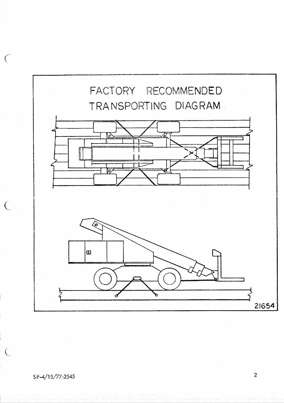
FACTO *Y RECOMMENDED
TRANSPO TING DIAGRAM
S P -4/15/77 :2545
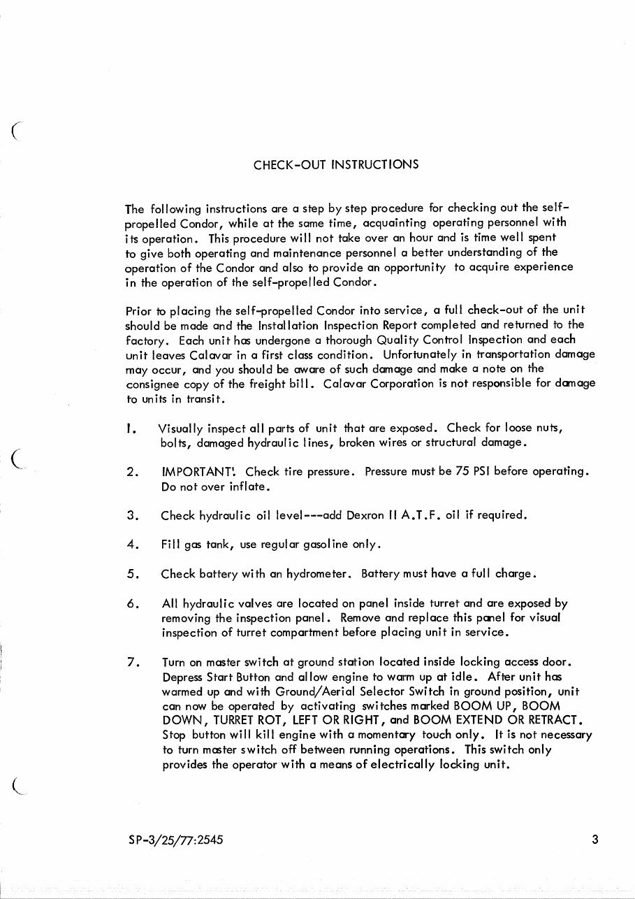
CHECK-OUT INSTRUCTIONS
The following instructions are a step by step procedure for checking out the self-
propelled Condor, while at the same time, acquainting operating personnel with
its operation. This procedure will not take over an hour and is time well spent
to give both operating and maintenance personnel a better understanding of the
operation of the Condor and also to provide an opportunity to acquire experience
in the operation of the self-propelled Condor.
Prior to placing the self-propelled Condor into service, a full check-out of the unit
should be made and the Installation Inspection Report completed and returned to the
factory. Each unit has undergone a thorough Quality Control Inspection and each
unit leaves Calavar in a first class condition. Unfortunately in transportation damage
may occur, and you should be aware of such damage and make a note on the
consignee copy of the freight bill. Calavar Corporation is not responsible for damage
to units in transit.
I. Visually inspect all parts of unit that are exposed. Check for loose nuts,
bolts, damaged hydraulic lines, broken wires or structural damage.
2. IMPORTANT. Check tire pressure. Pressure must be 75 PSI before operating.
Do not over inflate.
3. Check hydraulic oil level---add Dexron II A.T.F. oil if required.
4. Fill gas tank, use regular gasoline only.
5. Check battery with an hydrometer. Battery must have a full charge.
6. All hydraulic valves are located on panel inside turret and are exposed by
removing the inspection panel . Remove and replace this panel for visual
inspection of turret compartment before placing unit in service.
7. Turn on master switch at ground station located inside locking access door.
Depress Start Button and allow engine to warm up at idle. After unit has
warmed up and with Ground/Aerial Selector Switch in ground position, unit
can now be operated by activating switches marked BOOM UP, BOOM
DOWN, TURRET ROT, LEFT OR RIGHT, and BOOM EXTEND OR RETRACT.
Stop button will kill engine with a momentary touch only. It is not necessary
to turn master switch off between running operations. This switch only
provides the operator with a means of electrically locking unit.
S P-3/25/77:2545 3
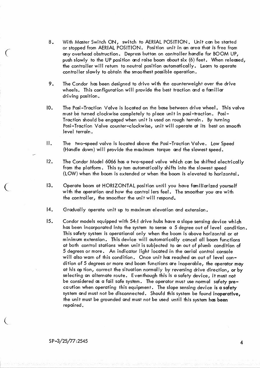
8. With Master Switch ON, switch to AERIAL POSITION. Unit can be started
or stopped from AERIAL POSITION. Position unit in an area that is free from
any overhead obstruction. Depress button on controller handle for BOOM UP,
push slowly to the UP position and raise boom about six (6) feet. When released,
the controller will return to neutral position automatically. Learn to operate
controller slowly to obtain the smoothest possible operation.
9. The Condor has been designed to drive with the counterweight over the drive
wheels. This configuration will provide the best traction and a familiar
driving position.
10. The Posi-Traction Valve is located on the base between drive wheel. This valve
must I:4 turned clockwise completely to place unit in posi-traction. Posi-
Traction should be engaged when unit is used on rough terrain. By turning
Posi-Traction Valve counter-clockwise, unit will operate at its best on smooth
level terrain.
I I . The two-speed valve is located above the Posi-Traction Valve. Low Speed
(Handle down) will provide the maximum torque and the slowest speed.
12. The Condor Model 6066 has a two-speed valve which can be shifted electrically
from the platform. This sy tern automatically shifts into the slowest speed
(LOW) when the boom is extended or when the boom is elevated to horizontal.
13. Operate boom at HORIZONTAL position until you have familiarized yourself
with the operation and how the control lers feel. The smoother you are with
the controller, the smoother the unit will respond.
14. Gradually operate unit up to maximum elevation and extension.
15. Condor models equipped with 54:1 drive hubs have a slope sensing device which
has been incorporated into the system to sense a 5 degree out of level condition.
This safely system is operational only when the boom is above horizontal or at
minimum extension. This device will automatically cancel all boom functions
at both control stations when unit is subjected to an out of plumb condition of
5 degrees or more. An indicator light located in the aerial control console
will also warn of this condition. Once unit has reached an out of level con-
dition of 5 degrees or more and boom functions are inoperable, the operator may
at his op tion, correct the situation normally by reversing drive direction, or by
selecting an alternate route. Eventhough this is a safety device, it must not
be considered as a fail safe system. The operator must use normal safety pre-
caution when operating this equipment. The slope sensing device is a safety
system and must not be disconnected. Should this system be found inoperative,
the unit must be grounded and must not be used until this system has been
repaired.
SP-3/25/77:2545
4
CALAVAR CORPORATION
Condor® Self-Propelled Aerial Work Platforms
WARRANTY
Calavar Corporation ("Calavar") warrants to the purchaser that each new aerial work platform made by Calavar is free
from defects in material and workmanship arising under normal use and service—in the case of major weldments,
(chassis, turret, and booms), for a period of five (5) years after the original shipment of the aerial work platform from
Calavar's plant; and in the case of all other parts, for a period of one (1) year after the aerial work platform is placed in
service or two (2) years after the original shipment of the aerial work platform from Calavar's plant, whichever comes
first.
The obligation and liability under this Warranty is expressly limited to repairing or, at Calavar's option, replacing free of
charge at its factory or at an authorized repair facility designated by Calavar, the defective part. I n no event shall Calavar
or its suppliers be liable to the purchaser or any other person for transportation charges or for any incidental, collateral,
special, or consequential damages, including without limitation damages for loss of profits, loss of customers, loss of
goodwill or work stoppage, claims by any party other than the purchaser, or any other similar damage or loss even if
Calavar, its suppliers, or its representatives have been advised of the possibility of such damages.
Parts claimed to be defective and for which repair or replacement is desired shall be returned transportation prepaid to
Calavar's factory for inspection. This Warranty applies to replacement parts provided under the terms of this Warranty
only for the remainder of the Warranty period applicable to the original purchase.
Any operation of the equipment beyond rated capacity, improper use or application of the equipment, substitution upon
it of parts not approved by Calavar or alteration or repair of the equipment by any person not authorized by Calavar shall,
at Calavar's option, void this Warranty. Calavar shall have no liability or responsi bility for dam ages resulting from accident
or the malfunction of equipment and components not supplied by Calavar.
No agent, employee, distributor, dealer, or other representative of Calavar is authorized to modify this Warranty in any
way. Accordingly, additional statements or presentations by any such representative, whether oral or written, do not
constitute warranties by Calavar and should not be relied upon as limited warranties of Calavar, and no attempt, effort,
or promise to repair equipment by Calavar or any such representative at any time shall modify or extend this Warranty
in any way. If the purchaser has used its own order form, no additional or different warranty terms contained in the
purchaser's form will be honored by Calavar. This Warranty covers only new and unused aerial work platforms
manufactured by Calavar. Products or parts manufactured by others are covered only by such warranties as are
extended to the purchaser by Calavar's suppliers.
This Warranty is in lieu of all other warranties, expressed or implied, including but not limited to warranties of
merchantibility and fitness for a particular purpose. Any applicable implied warranty shall be limited in duration to the
warranty period.
8300 Imperial Drive, P.O. Box 21447, Waco, Texas 76702-1447 • 817-666-4545, FAX 817-666-4544
Printed in U.S.A.
SEPTEMBER 1993
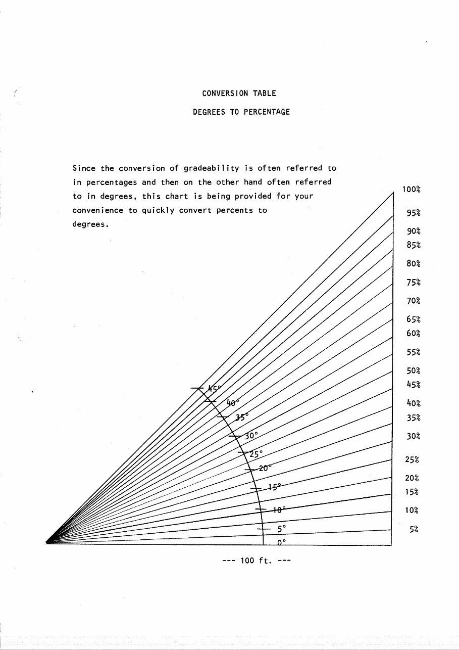
CONVERSION TABLE
DEGREES TO PERCENTAGE
Since the conversion of gradeability is often referred to
in percentages and then on the other hand often referred
to in degrees, this chart is being provided for your
convenience to quickly convert percents to
degrees.
100%
95%
90%
85%
80%
75%
70%
65%
60%
55%
50%
45%
40%
35%
30%
25%
20%
15%
10%
5%
--- 100 ft. --
You're Reading a Preview
What's Included?
Fast Download Speeds
Online & Offline Access
Access PDF Contents & Bookmarks
Full Search Facility
Print one or all pages of your manual
$41.99
Calavar self-propelled condor models 3238 4046 4248 4248E 5056 6066 Operation/maintenance and illustrated parts manual Instant D
Viewed 70 Times Today

What's Included?
Fast Download Speeds
Online & Offline Access
Access PDF Contents & Bookmarks
Full Search Facility
Print one or all pages of your manual
$41.99

Secure transaction
What's Included?
Fast Download Speeds
Online & Offline Access
Access PDF Contents & Bookmarks
Full Search Facility
Print one or all pages of your manual
Description
This is a comprehensive parts manual for the Calavar self-propelled condor models 3238, 4046, 4248, 4248E, 5056, and 6066. It provides detailed instructions and illustrated diagrams for maintenance and operation. The manual covers various sections including:
- Unloading Instructions
- Factory Recommended Tie Down and Transportation Diagram
- Check-out Instructions to Calavar Customer
- Calavar Warranty
- Conversion Tables, Degrees to Percentage
- General Information
- Hydraulic System
- Electrical System
- Mechanical Electric Adjustment
- Spare Parts List - Hydraulic and Electrical
- Lubrication Chart
- Oil Specification Sheet
- Troubleshooting Guide
- Preventative Maintenance
- General Specifications and Information
- Pneu-Trol Fluid Power Systems
- Michigan Fluid Power
- W.S .1. Drive Motor
- Torque Hub
- Braden Gear Box
- Char-Lynn
- Hunter Hydro Throttle Control
- Rotary Coupling
- Synchro Start (Diesel only)
- Honeywell Sensor Device
- John Deere
- Bertea , O. E. M.
- Wisconsin Engine
- Parts Breakdown
- Wiring Diagram
- Hydraulic Schematic
- Condor Operation and Safety
This manual is instantly accessible, eliminating shipping costs and waiting time. It is compatible with all versions of Windows and Mac, and requires Adobe Reader and WinZip for access. Whether you are a professional mechanic or a DIY enthusiast, this manual provides all the necessary information for maintaining and repairing the Calavar self-propelled condor models.


