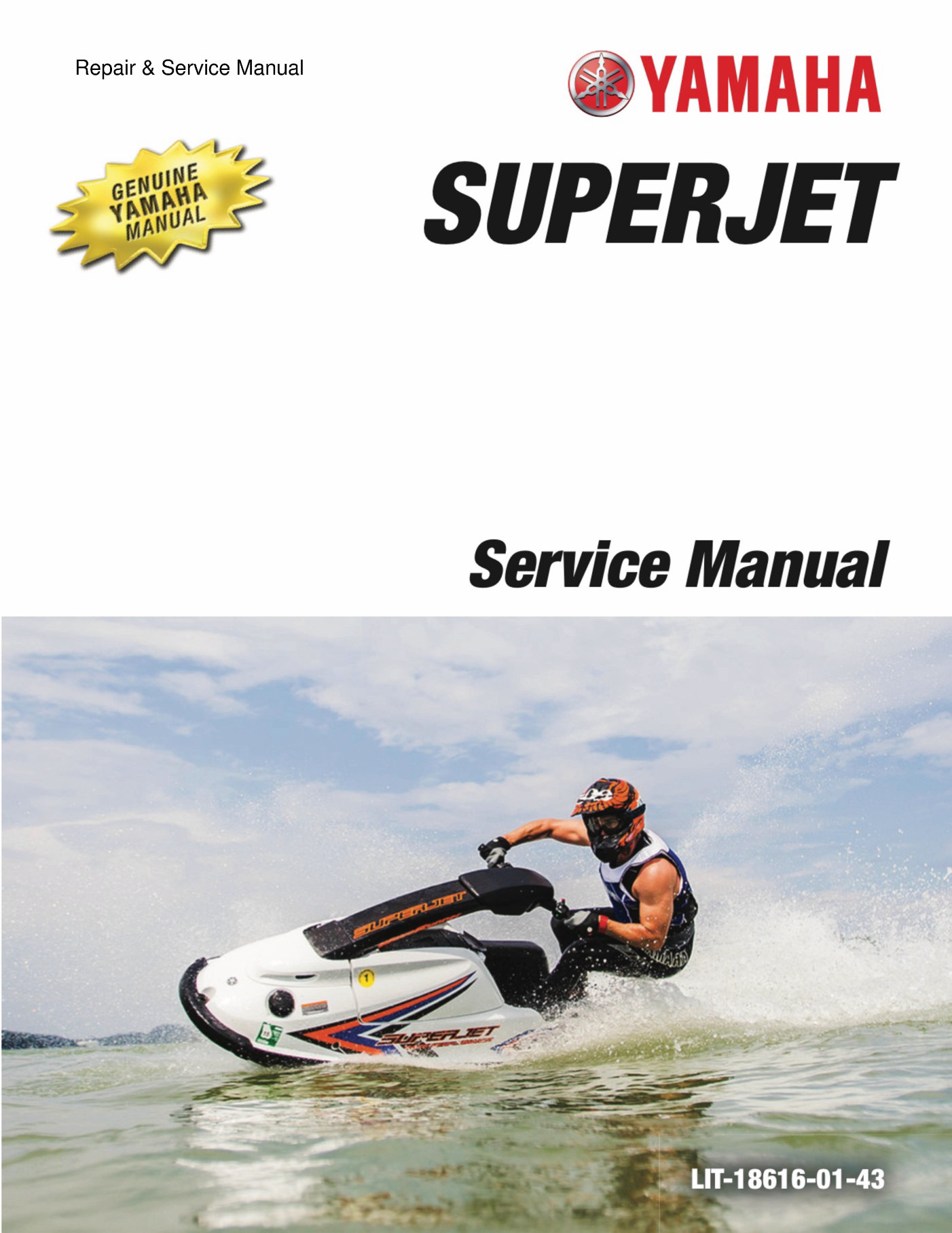
SUPERJET
Service Manual
~ LIT-18616-01-43
~
>)
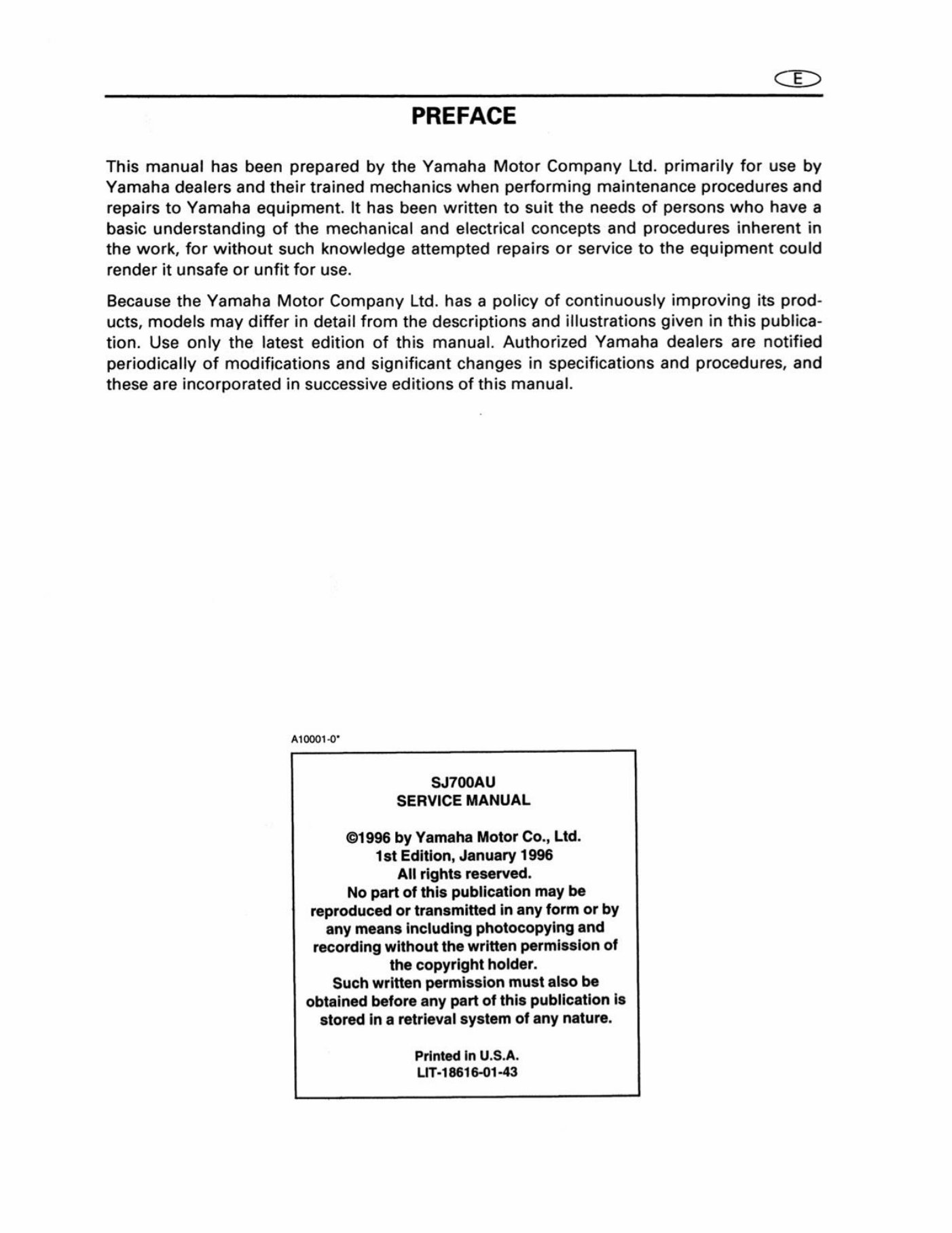
PREFACE
This manual has been preparedby the Yamaha Motor Company Ltd. primarily for use by
Yamaha dealers and their trained mechanics when performing maintenance procedures and
repairs to Yamaha equipment. It has been written to suit the needs of persons who have a
basic understanding of the mechanical and electrical concepts and procedures inherent in
the work, for without such knowledge attempted repairs or service to the equipment could
render it unsafe or unfit for use.
Because the Yamaha Motor Company Ltd. has a policy of continuously improving its prod-
ucts, models may differ in detail from the descriptions and illustrations given in this publica-
tion. Use only the latest edition of this manual. Authorized Yamaha dealers are notified
periodically of modifications and significant changes in specifications and procedures, and
these are incorporated in successive editions of this manual.
‘A10001-0"
SJ700AU
SERVICE MANUAL
©1996 by Yamaha Motor Co., Ltd.
1st Edition, January 1996
All rights reserved.
No part of this publication may be
reproduced or transmitted in any form or by
any means including photocopying and
recording without the written permission of
the copyright holder.
Such written permission must also be
obtained before any part of this publication is
stored in a retrieval system of any nature.
Printed in U.S.A.
LIT-18616-01-43
<e>
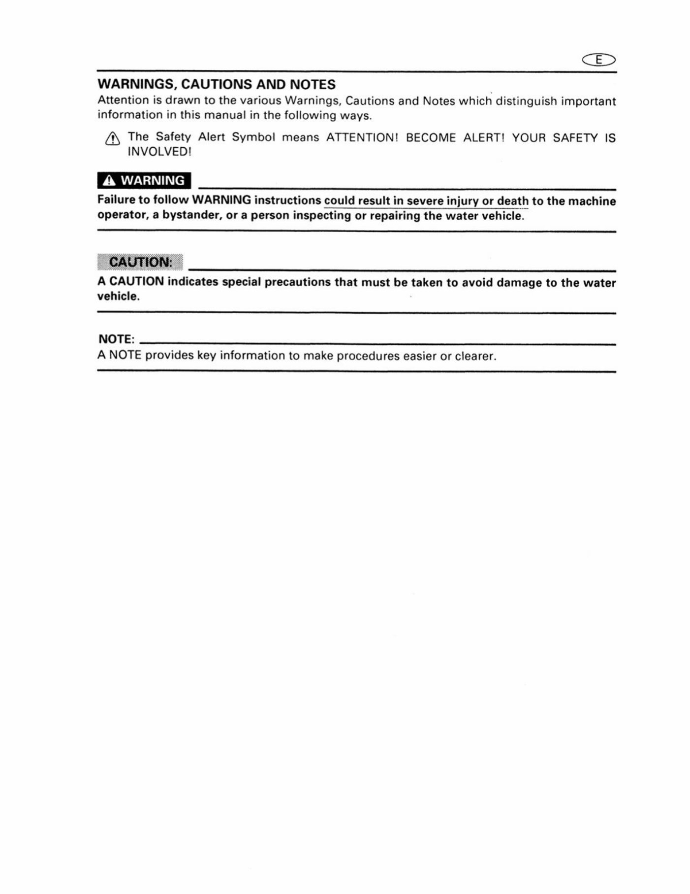
WARNINGS, CAUTIONS AND NOTES
Attention is drawn to the various Warnings, Cautions and Notes which distinguish important
information in this manual in the following ways.
Q) The Safety Alert Symbol means ATTENTION! BECOME ALERT! YOUR SAFETY IS
INVOLVED!
Failure to follow WARNING instructions could result in severe injury or death to the machine
operator, a bystander, or a person inspecting or repairing the water vehicle.
.
A CAUTION indicates special precautions that must be taken to avoid damage to the water
vehicle.
NOTE:
A NOTE provides key information to make procedures easier or clearer.
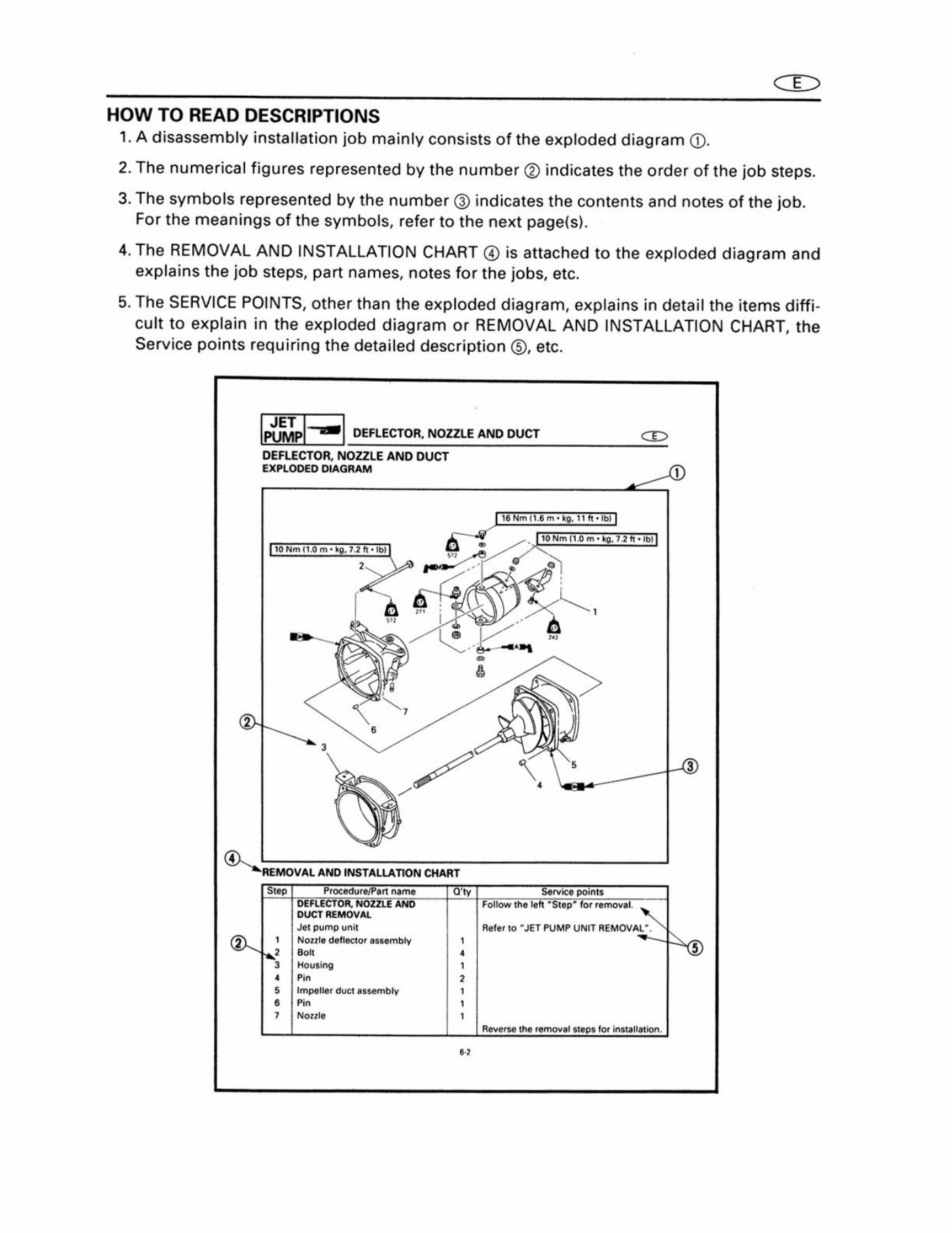
HOW TO READ DESCRIPTIONS
1. A disassembly installation job mainly consists of the exploded diagram ©.
2. The numerical figures represented by the number © indicates the order of the job steps.
3. The symbols represented by the number © indicates the contents and notes of the job.
For the meanings of the symbols, refer to the next page(s).
4. The REMOVAL AND INSTALLATION CHART @ is attached to the exploded diagram and
explains the job steps, part names, notes for the jobs, etc.
5. The SERVICE POINTS, other than the exploded diagram, explains in detail the items diffi-
cult to explain in the exploded diagram or REMOVAL AND INSTALLATION CHART, the
Service points requiring the detailed description ©, etc.
ET
Pinte |=) DEFLECTOR, NOZZLE AND DUCT (a2)
DEFLECTOR, NOZZLE AND DUCT
EXPLODED DIAGRAM _o
"REMOVAL AND INSTALLATION CHART
Step, Procedure/Pant name oy ‘Service points
DEFLECTOR, NOZZLE AND Foliow the left “Step” for removal
DUCT REMOVAL
Nozzle deflector assembly dais
Reverse the removal steps for installation.
CE>
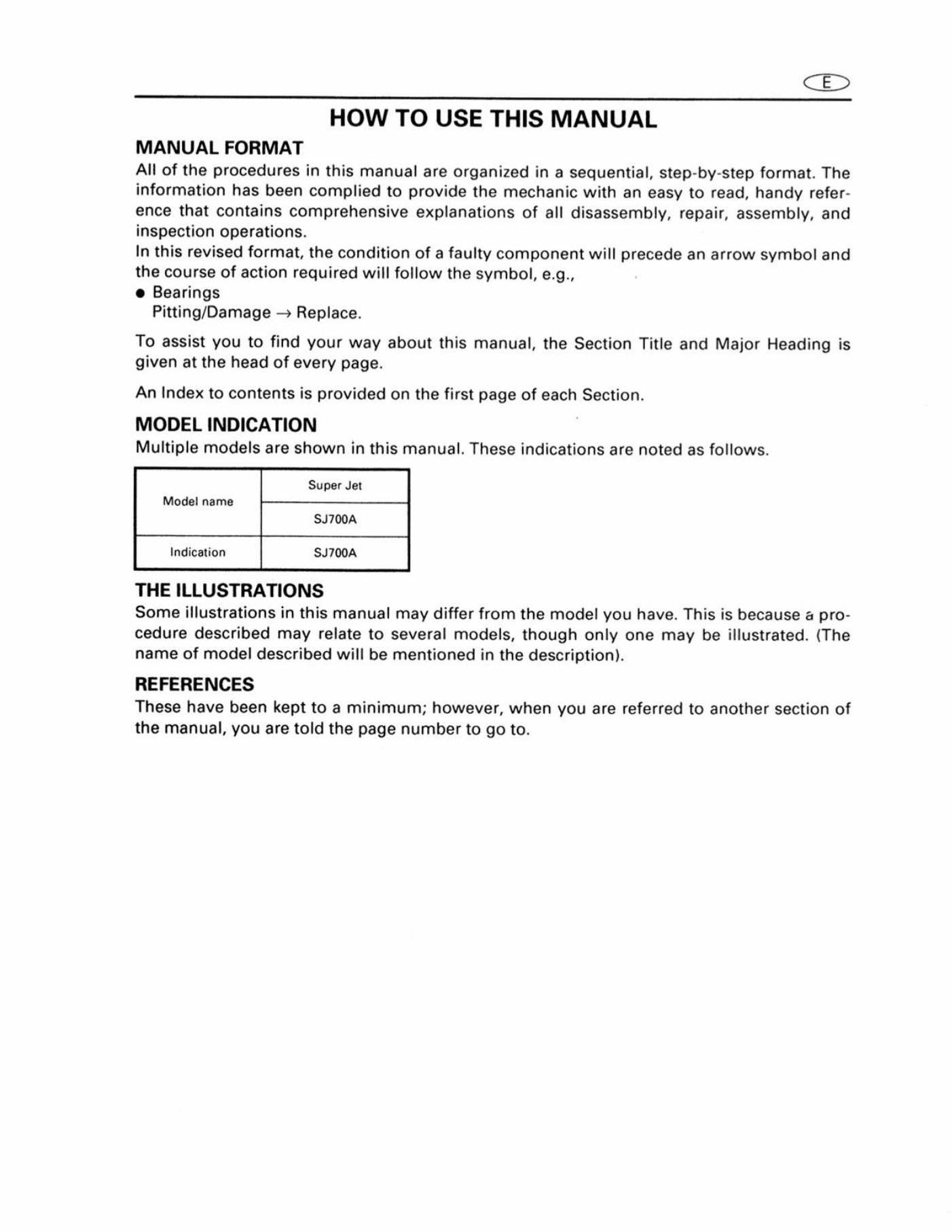
HOW TO USE THIS MANUAL
MANUAL FORMAT
All of the procedures in this manual are organized in a sequential, step-by-step format. The
information has been complied to provide the mechanic with an easy to read, handy refer-
ence that contains comprehensive explanations of all disassembly, repair, assembly, and
inspection operations.
In this revised format, the condition of a faulty component will precede an arrow symbol and
the course of action required will follow the symbol, e.g.,
@ Bearings
Pitting/Damage — Replace.
To assist you to find your way about this manual, the Section Title and Major Heading is
given at the head of every page.
An Index to contents is provided on the first page of each Section.
MODEL INDICATION
Multiple models are shown in this manual. These indications are noted as follows.
Super Jet
Model name
Indication SJ700A
THE ILLUSTRATIONS
Some illustrations in this manual may differ from the model you have. This is because a pro-
cedure described may relate to several models, though only one may be illustrated. (The
name of model described will be mentioned in the description).
REFERENCES
These have been kept to a minimum; however, when you are referred to another section of
the manual, you are told the page number to go to.
CED
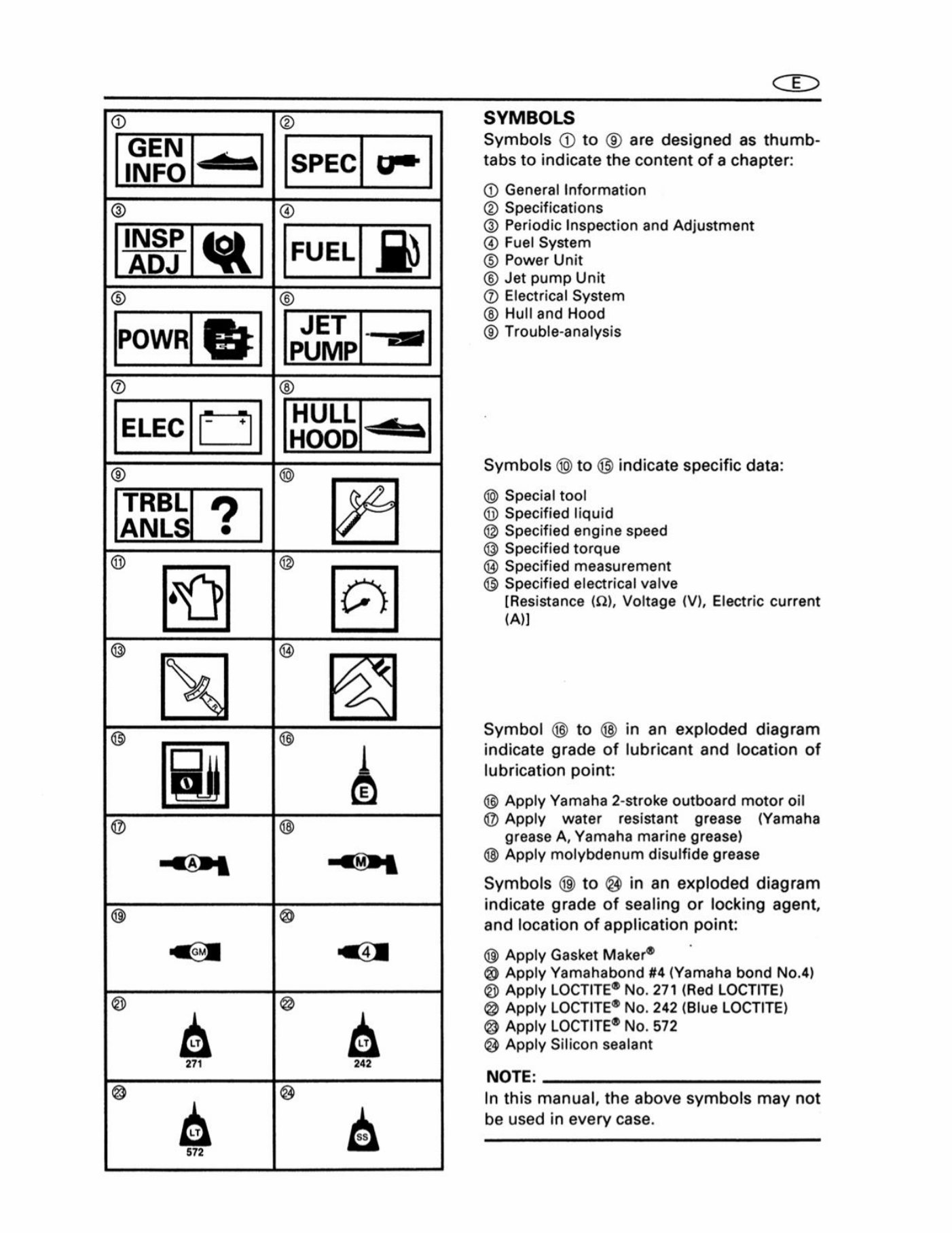
SYMBOLS
Symbols @ to © are designed as thumb-
tabs to indicate the content of a chapter:
@ General Information
® Specifications
© Periodic Inspection and Adjustment
@ Fuel System
© Power Unit
© Jet pump Unit
@ Electrical System
Hull and Hood
Trouble-analysis
Symbols @ to @ indicate specific data:
@ Special tool
@® Specified liquid
@ Specified engine speed
® Specified torque
@ Specified measurement
® Specified electrical valve
[Resistance (Q), Voltage (V), Electric current
(A)]
Symbol @ to in an exploded diagram
indicate grade of lubricant and location of
lubrication point:
@ Apply Yamaha 2-stroke outboard motor oil
@ Apply water resistant grease (Yamaha
grease A, Yamaha marine grease)
@ Apply molybdenum disulfide grease
Symbols @ to @ in an exploded diagram
indicate grade of sealing or locking agent,
and location of application point:
@® Apply Gasket Maker®
@ Apply Yamahabond #4 (Yamaha bond No.4)
® Apply LOCTITE® No. 271 (Red LOCTITE)
@ Apply LOCTITE® No. 242 (Blue LOCTITE)
@ Apply LOCTITE® No. 572
@ Apply Silicon sealant
NOTE:
In this manual, the above symbols may not
be used in every case.
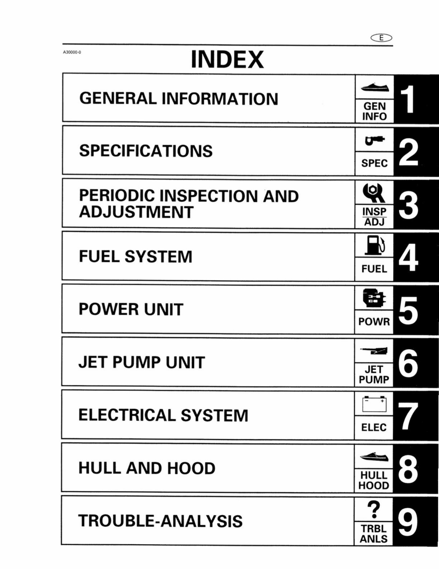
INDEX
GENERAL INFORMATION
SPECIFICATIONS
PERIODIC INSPECTION AND
ADJUSTMENT
FUEL SYSTEM
POWER UNIT
JET PUMP UNIT
ELECTRICAL SYSTEM
HULL AND HOOD
TROUBLE-ANALYSIS
©
CHAPTER 1
GENERAL INFORMATION
IDENTIFICATION NUMBERS
PRIMARY I.D. NUMBER...
ENGINE SERIAL NUMBER .
PUMP SERIAL NUMBER..
HULL IDENTIFICATION NUMBER
SAFETY WHILE WORKING
FIRE PREVENTION
VENTILATION...
SELF-PROTECTI
OILS, GREASES AND SEALING FLUIDS.
GOOD WORKING PRACTICES ...
DISASSEMBLY AND ASSEMBLY .
SPECIAL TOOLS ...
MEASURING ..
REMOVAL AND INSTALLATION
IDENTIFICATION NUMBERS cE
1-1
‘A60700-0°
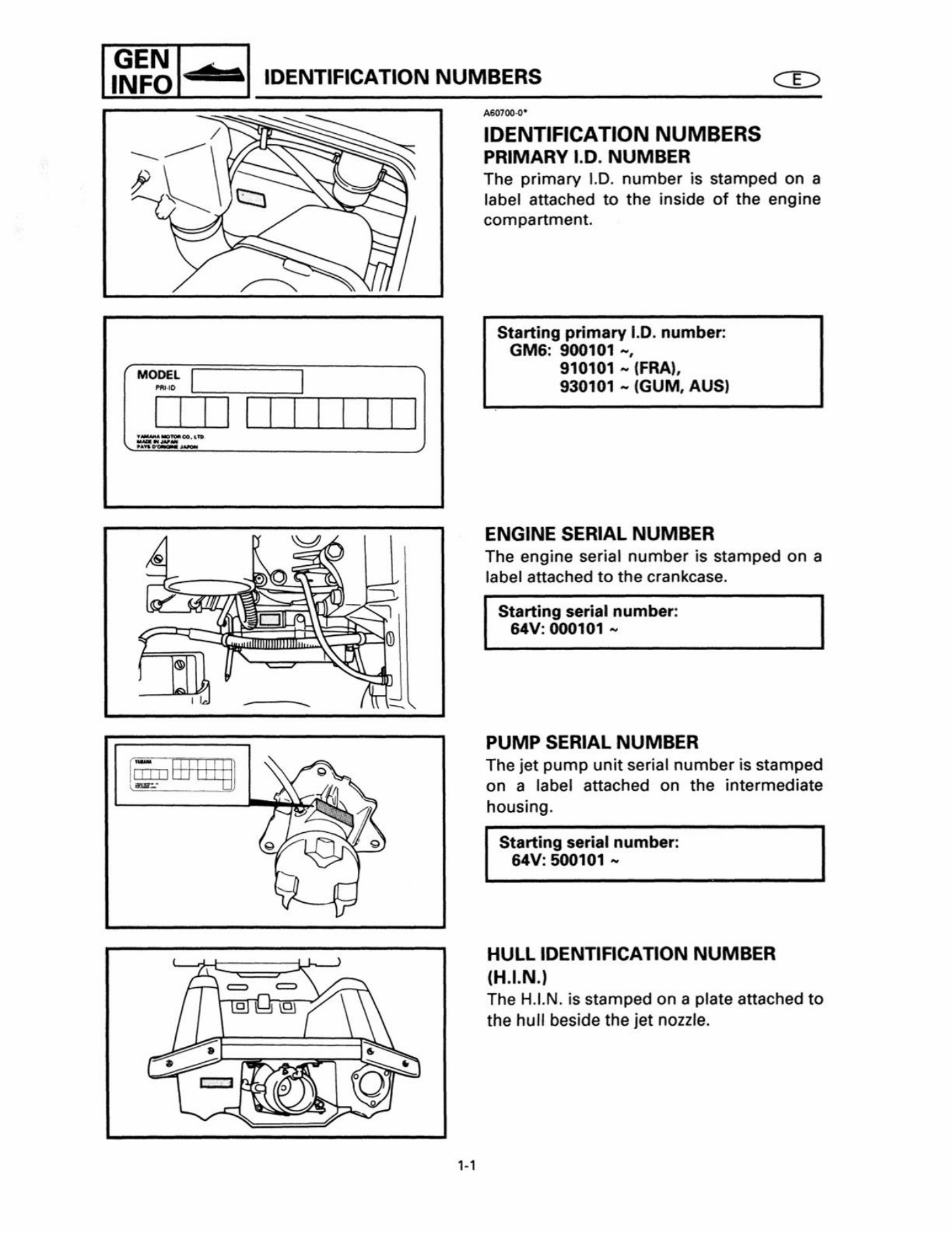
IDENTIFICATION NUMBERS
PRIMARY I.D. NUMBER
The primary |.D. number is stamped on a
label attached to the inside of the engine
compartment.
Starting primary I.D. number:
GM6: 900101 ~,
910101 ~ (FRA),
930101 ~ (GUM, AUS)
ENGINE SERIAL NUMBER
The engine serial number is stamped on a
label attached to the crankcase.
Starting serial number:
64V: 000101 ~
PUMP SERIAL NUMBER
The jet pump unit serial number is stamped
on a label attached on the intermediate
housing.
Starting serial number:
64V: 500101 ~
HULL IDENTIFICATION NUMBER
(H.1.N.)
The H.I.N. is stamped on a plate attached to
the hull beside the jet nozzle.
You're Reading a Preview
What's Included?
Lifetime Access
Access PDF Contents & Bookmarks
Print one or all pages of your manual


 Lifetime Access




