© 2006 PDF Manual Master
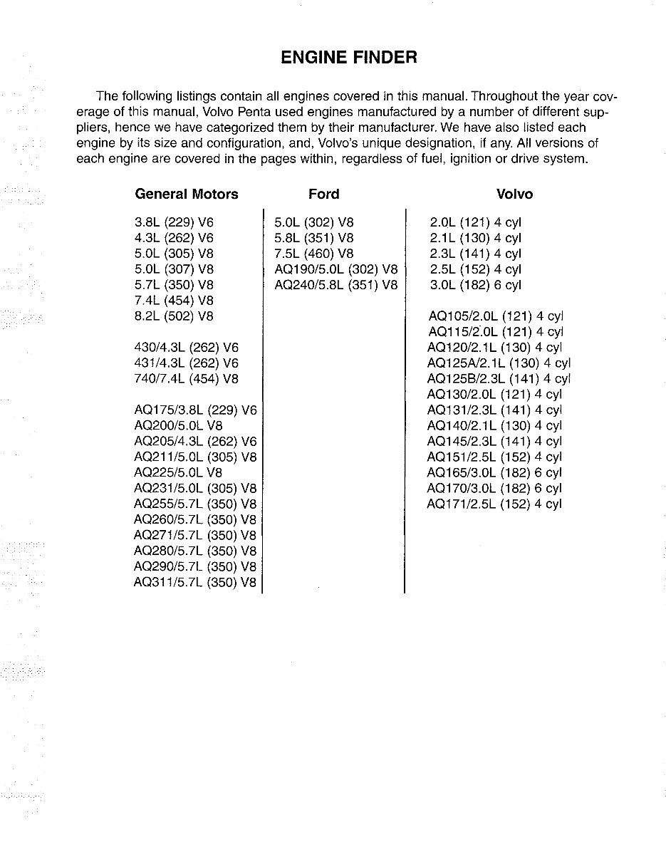
ENGINE FINDER
The following listings contain all engines covered in this manual. Throughout the year cov-
erage of this manual, Volvo Penta used engines manufactured by a number of different sup-
pliers, hence we have categorized them by their manufacturer. We have also listed each
engine by its size and configuration, and, Volvo's unique designation, if any. All versions of
each engine are covered in the pages within, regardless of fuel, ignition or drive system.
General Motors
3.SL (229) V6
4.3L (262) V6
5.0L (305) VS
5.0L (307) VS
5.7L (350) VS
7.4L (454) VS
S.2L (502) VS
430/4.3L (262) V6
431/4.3L (262) V6
740/7.4L (454) VS
AQ175/3.SL (229) V6
AQ200/5.0L VS
AQ205/4.3L (262) V6
AQ211/5.0L (305) VS
AQ225/5.0L VS
AQ231/5.0L (305) VS
AQ255/5.7L (350) VS
AQ260/5.7L (350) VS
AQ271/5.7L (350) VS
AQ2S0/5.7L (350) VS
AQ290/5.7L (350) VS
AQ311/5.7L (350) VS
Ford
5.0L (302) VS
5.SL (351) VS
7.5L (460) VS
AQ190/5.0L (302) VS
AQ240/5.SL (351) VS
Volvo
2.0L (121) 4 cyl
2.1 L (130) 4 cyl
2.3L (141) 4 cyl
2.5L (152) 4 cyl
3.0L (1S2) 6 cyl
AQ105/2.0L (121) 4 cyl
AQ115/2.0L (121) 4 cyl
AQ120/2.1L (130) 4 cyl
AQ125A12.1 L (130) 4 cyl
AQ1258/2.3L (141) 4 cyl
AQ130/2.0L (121) 4 cyl
AQ131/2.3L (141) 4 cyl
AQ140/2.1 L (130) 4 cyl
AQ145/2.3L (141) 4 cyl
AQ151/2.5L (152) 4 cyl
AQ165/3.0L (1S2) 6 cyl
AQ170/3.0L (1S2) 6 cyl
AQ171/2.5L (152) 4 cyl
© 2006 PDF Manual Master
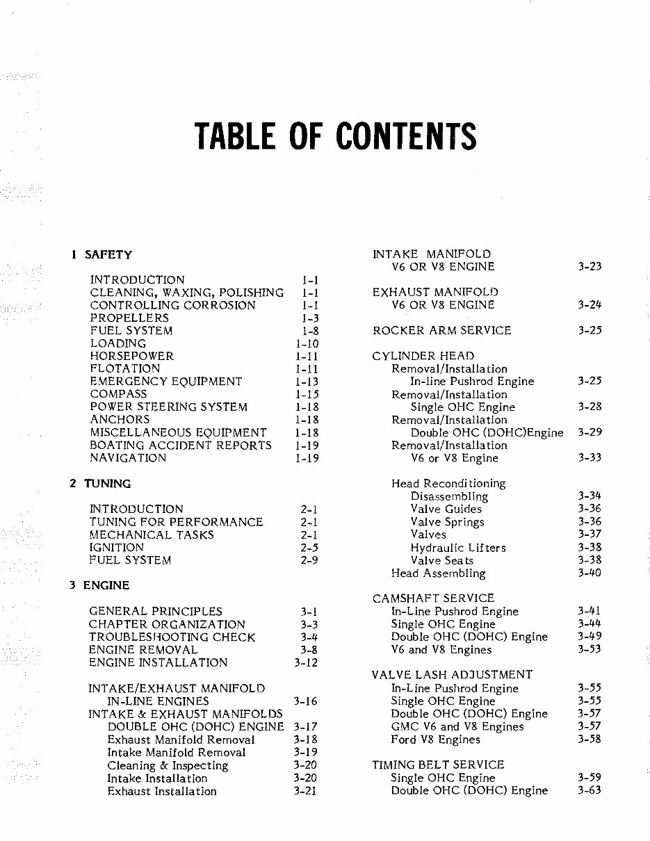
TABLE OF CONTENTS
1 SAFETY INTAKE MANIFOLD
V6 OR V8 ENGINE 3-23
INTRODUCTION 1-1
CLEANING, WAXING, POLISHING 1-1 EXHAUST MANIFOLD
CONTROLLING CORROSION 1-1 V6 OR V8 ENGINE 3-24
PROPELLERS 1-3
FUEL SYSTEM 1-8 ROCKER ARM SERVICE 3-25
LOADING 1-10
HORSEPOWER 1-11 CYLINDER HEAD
FLOTATION 1-11 Removal/Installa tion
EMERGENCY EQUIPMENT 1-13 In-line Pushrod Engine 3-25
COMPASS 1-15 Removal/Installation
POWER STEERING SYSTEM 1-18 Single OHC Engine 3-28
ANCHORS 1-18 Re mo v al/Installa ti on
MISCELLANEOUS EQUIPMENT 1-18 Double OHC (DOHC)Engine 3-29
BOATING ACCIDENT REPORTS 1-19 Removal/Installa tion
NAVIGATION 1-19 V6 or V8 Engine 3-33
2 TUNING Head Recondi tioning
Disassembling 3-34
INTRODUCTION 2-1 Valve Guides 3-36
TUNING FOR PERFORMANCE 2-1 Valve Springs 3-36
MECHANICAL TASKS 2-1 Valves 3-37
IGNITION 2-5 Hydraulic Lifters 3-38
FUEL SYSTEM 2-9 Valve Seats 3-38
Head Assembling 3-40
3 ENGINE
CAMSHAFT SERVICE
GENERAL PRINCIPLES 3-1 In-Line Pushrod Engine 3-41
CHAPTER ORGANIZATION 3-3 Single OHC Engine 3-44
TROUBLESHOOTING CHECK 3-4 Double OHC (DOHC) Engine 3-49
ENGINE REMOVAL 3-8 V6 and V8 Engines 3-53
ENGINE INSTALLATION 3-12
VALVE LASH ADJUSTMENT
INT AKE/EXHAUST MANIFOLD In-Line Pushrod Engine 3-55
IN-LINE ENGINES 3-16 Single OHC Engine 3-55
INTAKE &: EXHAUST MANIFOLDS Double OHC (DOHC) Engine 3-57
DOUBLE OHC (DOHC) ENGINE 3-17 GMC V6 and V8 Engines 3-57
Exhaust Manifold Removal 3-18 Ford V8 Engines 3-58
Intake Manifold Removal 3-19
Cleaning &: Inspecting 3-20 TIMING BELT SERVICE
Intake Installation 3-20 Single OHC Engine 3-59
Exhaust Installation 3-21 Double OHC (DOHC) Engine 3-63
© 2006 PDF Manual Master
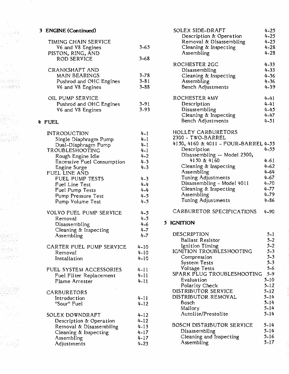
3 ENGINE (Continued) SOLEX SIDE-DRAFT 4-25
Description & Operation 4-25
TIMING CHAIN SERVICE Removal & Disassembling 4-25
V6 and V8 Engines 3-65 Cleaning & Inspecting 4-28
PISTON, RING, AND Assembling 4-28
ROD SERVICE 3-68
ROCHESTER 2GC 4-33
CRANKSHAFT AND Disassembling 4-33
MAIN BEARINGS 3-78 Cleaning & Inspecting 4-36
Pushrod and OHC Engines 3-81 Assembling 4-36
V6 and V8 Engines 3-88 Bench Adjustments 4-39
OIL PUMP SERVICE ROCHESTER 4MV 4-41
Pushrod and OHC Engines 3-91 Description 4-41
V 6 and V8 Engines 3-93 Disassembling 4-45
Cleaning & Inspecting 4-47
4 FUEL
Bench Adjustments 4-51
INTRODUCTION 4-1
HOLLEY CARBURETORS
Single Diaphragm Pump 4-1
2300 - TWO-BARREL
Dual-Diaphragm Pump 4-1
4150, 4160 & 4011 - FOUR-BARREL 4-55
TROUBLESHOOTING 4-1
Description 4-55
Rough Engine Idle 4-2
Disassembling -- Model 2300,
Excessive Fuel Consumption 4-3
4150 & 4160 4-61
Engine Surge 4-3
Cleaning & Inspecting 4-62
FUEL LINE AND
Assembling 4-64
FUEL PUMP TESTS 4-3
Tuning Adjustments 4-67
Fuel Line Test 4-4
Disassembling - Model 4011 4-70
Fuel Pump Tests 4-4
Cleaning & Inspecting 4-77
Pump Pressure Test 4-5
Assembling 4-79
Pump Volume Test 4-5
Tuning Adjustmen ts 4-86
VOLVO FUEL PUMP SERVICE 4-5
CARBURETOR SPECIFICATIONS 4-90
Removal 4-5
Disassembling 4-6
5 IGNmON
Cleaning & Inspecting 4-7
Assembling 4-7
DESCRIPTION 5-1
Ballast Resistor 5-2
CARTER FUEL PUMP SERVICE 4-10
Igni tion Timing 5-2
Removal 4-10
IGNITION TROUBLESHOOTING 5-3
Installa tion 4-10
Compression 5-3
System Tests 5-3
FUEL SYSTEM ACCESSORIES 4-11
Voltage Tests 5-6
Fuel Filter Replacement 4-11
SPARK PLUG TROUBLESHOOTING 5-9
Flame Arrester 4-11
Evaluation 5-10
Polar i ty Check 5-12
CARBURETORS
DISTRIBUTOR SERVICE 5-12
Introduction 4-11
DISTRIBUTOR REMOVAL 5-14
"Sour" Fuel 4-12
Bosch 5-14
Mallory 5-14
SOLEX DOWNDRAFT 4-12
Autoli te/Prestolite 5-14
Description & Operation 4-12
Removal & Disassembling 4-13
BOSCH DISTRIBUTOR SERVICE 5-14
Cleaning & Inspecting 4-17
Disassembling 5-14
Assembling 4-17
Cleaning and Inspecting 5-16
Adjustments 4-23
Assembling 5-17
© 2006 PDF Manual Master
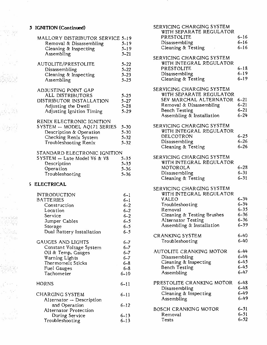
5 IGNITION (Continued)
SERVICING CHARGING SYSTEM
WITH SEPARATE REGULATOR
MALLORY DISTRIBUTOR SERVICE 5-19
PRESTOLITE 6-16
Removal & Disassembling 5-19
Disassembling 6-16
Cleaning & Inspecting 5-19
Cleaning & Testing 6-16
Assembling 5-21
SERVICING CHARGING SYSTEM
AUTOLITE/PRESTOLITE 5-22
WITH INTEGRAL REGULA TOR
Disassembling 5-22
PRESTOLITE 6-18
Cleaning & Inspecting 5-23
Disassembling 6-19
Assembling 5-25
Cleaning & Testing 6-19
ADJUSTING POINT GAP
SERVICING CHARGING SYSTEM
ALL DISTRIBUTORS 5-25
WITH SEPARATE REGULA TOR
DISTRIBUTOR INSTALLATION 5-27
SEV MARCHAL AL TERNA TOR 6-21
Adjusting the Dwell 5-28
Removal & Disassembling 6-21
Adjusting Ignition Timing 5-29
Bench Testing 6-21
Assembling & Installation 6-24
RENIX ELECTRONIC IGNITION
SYSTEM -- MODEL AQ171 SERIES 5-30
SERVICING CHARGING SYSTEM
Description & Operation 5-30
WITH INTEGRAL REGULA TOR
Checking Renix System 5-32
DEL COT RON 6-25
Troubleshooting Renix 5-32
Disassembling 6-26
Cleaning & Testing 6-26
ST ANDARD ELECTRONIC IGNITION
SYSTEM -- Late Model V6 & V8 5-35
SERVICING CHARGING SYSTEM
Description 5-35
WITH INTEGRAL REGULA TOR
Operation 5-36
MOTOROLA 6-28
Troubleshooting 5-36
Disassembling 6-31
Cleaning & Testing 6-31
,.
ELECTRICAL :>
SERVICING CHARGING SYSTEM
INTRODUCTION 6-1
WITH INTEGRAL REGULA TOR
BATTERIES 6-1
VALEO 6-34
Construction 6-2
Troubleshooting 6-34
Location 6-2
Removal 6-35
Service 6-2
Cleaning & Testing Brushes 6-36
Jumper Cables 6-5
Alternator Testing 6-36
Storage 6-5
Assembling & Installation 6-39
Dual Ba ttery Installation 6-5
CRANKING SYSTEM 6-40
GAUGES AND LIGHTS 6-7
Troubleshooting 6-40
Constant Voltage System 6-7
Oil & Temp. Gauges 6-7
AUTOLITE CRANKING MOTOR 6-44
Warn ing Ugh ts 6-7
Disassembling 6-44
Thermomelt Sticks 6-8
Cleaning & Inspecting 6-45
Fuel Gauges 6-8
Bench Testing 6-45
Tachometer 6-10
Assembling
6-47
HORNS 6-11
PRESTOLITE CRANKING MOTOR 6-48
Disassembling 6-48
CHARGING SYSTEM 6-11
Cleaning & Inspecting 6-49
Alternator -- Description
Assembling 6-49
and Operation 6-12
Alternator Protection
BOSCH CRANKING MOTOR 6-51
During Service 6-13
Removal 6-51
Troubleshooting 6-13
Tests 6-52
© 2006 PDF Manual Master
6 ELECTRICAL (Continued)
DUOPROP
LOWER UNIT 8-63
BOSCH CRANKING MTR. (Cont.)
Propeller Service 8-63
Disassembling 6-53
Propeller Removal 8-63
Cleaning & Inspecting 6-55
Propeller Installa tion 8-65
Assembling 6-56
Pre para tion for Service 8-67
Testing Completed Work 6-59
Disassembling 8-68
Installa tion 6-59
Cleaning & Inspecting 8-75
Assembling 8-77
DELCO CRANKING MOTOR 6-62
Shim Calculations 8-79
Servicing & Testing 6-62
Assembling Continues 8-83
Assembling 6-64
Checking Backlash 8-87
7 COOLING
9 TILT/TRIM
DESCRIPTION 7-1
INTRODUCTION 9-1
"RAW" WATER STRAINER 7-4
Tilt 9-1
HEAT EXCHANGER 7-5
Trim 9-1
"RAW" WATER PUMP 7-7
TROUBLESHOOTING 9-2
THERMOSTAT 7-9
OIL COOLER 7-9
TILT SYSTEM SERVICE
Removal & Disassembling 9-4
8 STERN DRIVE
Cleaning & Inspec ling 9-9
Assembling & Installation 9-9
INTRODUCTION 8-1
Operation 8-1
TRIM SYSTEM SERVICE
TROUBLESHOOTING 8-2
Removal & Disassembling 9-13
Stern Drive Noises 8-2
Cleaning & Inspec ting 9-14
Service Precau tions 8-3
Assembling & Installation 9-15
PROPELLER SERVICE 8-3
Removal 8-3
TRIM SENDER SERVICE
"Frozen" Propeller 8-4
Replace Wire 9-16
Change Propeller Rotation 8-5
Retaining Pawl Adjustment 8-5
10 STEERING
Propeller Installation 8-6
DESCRIPTION 10-1
STERN DRIVE
SERVO VALVE ADJUSTMENT 10-3
Removal 8-8
POWER STEERING COOLER 10-4
Installation 8-10
POWER STEERING KIT 10-4
UPPER GEAR ASSEMBLY 8-12
11 MAINTENANCE
Disassembling 8-13
Cleaning & Inspecting 8-19
IN-SEASON MAINTENANCE 11···1
Assembling 8-21
Before Starting - First Time 11-1
Every 2 Weeks 11-1
INTERMEDIATE HOUSING
Every 50 Hours 11-1
Disassembling 8-36
Every 100 Hours 11-4
Cleaning & Inspecting 8-41
Retaining Pawl Adjustment 11-5
Assembling 8-42
OFF-SEASON STORAGE 11-5
PRE-SEASON PREPARATION 11-8
STANDARD PROPELLER
ADJUSTING BOAT TRIM 11-10
LOWER UNIT 8-47
ADJUSTING TRIM TAB 11-10
Preparation 8-47
FIBERGLASS HULLS 11-10
Disassembling 8-48
BELOW WATERLINE SERVICE 11-11
Cleaning & Inspecting 8-52
Assembling
8-54
GIMBAL HOUSING -- EXPLODED
EXTENSIONS 8-62
DRAWING 11-12
© 2006 PDF Manual Master
APPENDIX
Engine AQ190A & 240A A-49
METRIC CONVERSION CHART A-I
DRILL SIZE CONVERSION CHART A-2
Complete AQ205, AQ21IA, AQ231,
REPLACEMENTP5TONS
AQ271C & AQ31lA & B A-50
AQ125 AND AQ145 ENGINES A-3
V ALVE ADJUSTING KIT
Model 431 A-51
AQ125 AND AQ145 ENGINES A-3
TUNE-UP ADJUSTMENTS A-4
Instrument Panel AQ200AB
& AQ290A with ammeter A-52
ENGINE SPECIFICATIONS
4-Cylinder OHC
Engine AQ200AB, AQ225 AB,
AQI20B, AQI25A, AQI40A,
& AQ290A with ammeter A-53
AND AQ145A A-8
Instrument Panel AQ200AB,
4-Cylinder OHC & DOHC
AQ225AB &. AQ290A with
AQI25B, AQ131 A, AQI45B,
voltmeter A-54
AQI5IA, AND AQ171A A-14
Engine AQ200AB, AQ225AB
4- & 6-Cylinder In-Line
& AQ290A with voltmeter A-55
AQ105A, AQ1l5A, AQ130A,
Complete AQ200C, AQ225C,
B, C & D, AQ165A,
and AQI70A, B &. C A-20
& AQ225A with ammeter A-56
GMC V6 AQ175A A-25
Complete AQ200C AQ225C,
& AQ225A with voltmeter A-57
GMC V6 Model 431 A-28
GMC V6 305CID, 307CID,
Instrument Panel AQ280A
350CID & 454CID A-32
& AQ225A A-58
Ford V8 AQ190A & AQ240A A-37
Engine AQ280A & AQ225A A-59
HOLLEY CARBURETOR SPECS. A-41
Complete Model 740 A-60
TORQUE SPECS. AQl90A
Instrument Panel with ammeter
AND AQ240A A-41
and with voltmeter --
AQ200D, AQ225D, AQ260A
WIRE IDENTIFICATION DWGS.
& D, AQ290A, and all other
AQ105A, AQ115A,
GMC V6, V8, and Ford V8 A-61
AQ130A, B, C, & D,
AQ165A, & AQl70A A-42
Power Tilt -- USA A-62
Complete AQI20B, AQ125A
Power Til t -- all except USA A-63
& B, AQ140A, AQ145A & B A-43
Power Trim -- Single Station
Complete AQ131A, AQ151A
with trim gauge and
&B A-44
trim limit switch A-64
Complete AQ171A A-45
Power Trim -- Dual Station
with trim gauge and
Complete AQ175A A-46
trim limit switch A-65
Early Model AQ200D, AQ225D,
Power Trim -- Late Type --
AND AQ255D A-47
Single Station with
Instrument Panel AQ190A
trim gauge and trim
& AQ240A with voltmeter A-48
limit switch A-66
© 2006 PDF Manual Master
1
SAFETY
1-1 INTRODUCTION
Your boat probably represents a sizeable
investm ent f or you. In order to protect this
investment and to receive the maximum
amount of enjoyment from your boat it must
be cared for properly while being used and
when it is out of the water. Always store
your boat with the bow higher than the stern
and be sure to remove the transom drain
plug and the inner hull drain plugs. If you
use any type of cover to protect your boat,
plastic, canvas, whatever, be sure to allow
for some movement of air through the hull.
Proper ventilation will assure evaporation of
any condensation that may form due to
changes in temperature and humidity.
1-2 CLEANING, WAXING, AND POLISHING
Any boat should be washed with clear
water after each use to remove surface dirt
and any salt deposits from use in salt water.
Regular rinsing will extend the time be-
tween waxing and polishing. It will also give
you "pride of ownership", by having a sharp
looking piece of equipment. Elbow grease, a
mild detergent, and a brush will be required
to remove stubborn dirt, oil, and other un-
sightly deposits.
Stay away from harsh abrasives or strong
chemical cleaners. A white buffing com-
pound can be used to restore the original
gloss to a scratched, dull, or faded area.
The finish of your boat should be thoroughly
cleaned, buffed, and polished at least once
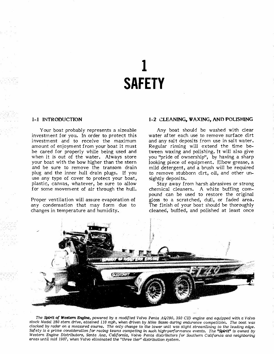
The Spirit of Western Engine, powered by a modified Volvo Penta AQ290, 350 CID engine and equipped with a Volvo
stock Model 280 stern drive, attained 110 mph, when driven by Mike Basso during endurance competition. The boat was
clocked by radar on a measured course. The only change to the lower unit was slight streamlining to the leading edge.
Safety is a prime consideration for racing teams competing in such high-performance events. The "Spirit" is owned by
Western Engine Distributors, Santa Ana, California, Volvo Penta distributors for Southern Califomia and neighboring
areas until mid 1987, when Volvo eliminated the "three tier" distribution system.
© 2006 PDF Manual Master
1-2 SAFETY
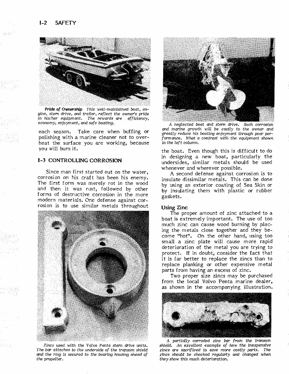
Pride of Ownership This well-maintained boat, en-
gine, stem drive, and trailer, reflect the owners pride
in his/her equipment. The rewards are efficiency,
economy, enjoyment, and safe boating.
each season. Take care when buffing or
polishing with a marine cleaner not to over-
heat the surface you are working, because
you will burn it.
1-3 CONTROLLING CORROSION
Since man first started out on the water,
corrosion on his craft has been his enemy.
The first form was merely rot in the wood
and then it was rust, followed by other
forms of destructive corrosion in the more
modern materials. One defense against cor-
rosion is to use similar metals throughout
Zincs used with the Volvo Penta stern drive units.
The bar attaches to the underside of the transom shield
and the ring is secured to the bearing housing ahead of
the propeller.
A neglected boat and stern drive. Such corrosion
and marine growth will be costly to the owner and
greatly reduce his boating enjoyment through poor per-
formance. What a contrast with the equipment shown
in the left column.
the boat. Even though this is difficult to do
in designing a new boat, particularly the
undersides, similar metals should be used
whenever and wherever possible.
A second defense against corrosion is to
insulate dissimilar metals. This can be done
by using an exterior coating of Sea Skin or
by insulating them with plastic or rubber
gaskets.
Using Zinc
The proper amount of zinc attached to a
boat is extremely important. The use of too
much zinc can cause wood burning by plac-
ing the metals close together and they be-
come "hot". On the other hand, using too
small a zinc plate will cause more rapid
deterioration of the metal you are trying to
protect. If in doubt, consider the fact that
it is far better to replace the zincs than to
replace planking or other expensive metal
parts f rom having an excess of zinc.
Two proper size zincs may be purchased
from the local Volvo Penta marine dealer,
as shown in the accompanying lllustration.
A partially corroded zinc bar from the transom
shield. An excellent example of how the inexpensive
zincs are sacrificed to save more costly parts. The
zincs should be checked regularly and changed when
they show this much deterioration.
© 2006 PDF Manual Master
A Volvo Penta spare parts kit includes a raw water
pump impeller, set of spark plugs, condenser, V-belt for
the alternator, and a fuse. Such a kit, sold at modest
cost, could prove most valuable in an emergency situa-
tion. A zinc bar and ring (lower right), and a spare oil
filter (Zeft), might be added to the kit by the prudent
boat owner.
The bar attaches to the underside of the
transom shield and the ring is secured to the
double bearing housing ahead of the propel-
ler.
The other illustration on the previous
page is an excellent example of how the
inexpensive zincs are sacrificed to save
more costly parts. The zincs should be
checked regularly and changed when they
show signs of deteriorating.
1-4 PROPELLERS
As you know, the propeller is actually
what moves the boat through the water.
This is how it is done. The propeller oper-
ates in water in much the manner as a wood
screw does in wood. The propeller "bites"
into the water as it rotates. Water passes
between the blades and out to the rear in
"""I .. _--- 10"
o
o 0
o
PROPELLERS 1-3
ITATION BURN
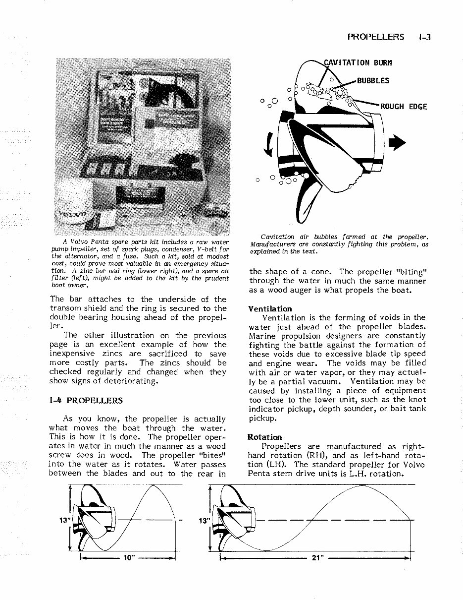
Cavitation air bubbles formed at the propeller.
Manufacturers are constantly fighting this problem, as
explained in the text.
the shape of a cone. The propeller "biting"
through the water in much the same manner
as a wood auger is what propels the boat.
Ventilation
Ventilation is the forming of voids in the
wa ter just ahead of the propeller blades.
Marine propUlsion designers are constantly
fighting the battle against the formation of
these voids due to excessive blade tip speed
and engine wear. The voids may be filled
with air or water vapor, or they may actual-
ly be a partial vacuum. Ventilation may be
caused by installing a piece of equipment
too close to the lower unit, such as the knot
indicator pickup, depth sounder, or bait tank
pickup.
Rotation
Propellers are manufactured as right-
hand rotation (RH), and as left-hand rota-
tion (LH). The standard propeller for Volvo
Penta stem drive units is L.H. rotation.
21"
You're Reading a Preview
What's Included?
Lifetime Access
Access Contents & Bookmarks
Print one or all pages of your manual