



Quick Reference Data
MAINTENANCE TORQUE SPECIFICATIONS
Fastener in.-lb. ft.-lb. N•m
Drive unit dipstick 48-72 – 5.4-8.1
Drive unit lubricant vent plug 48-72 – 5.4-8.1
Drive unit drain/fill plug 60-84 – 6.8-9.5
Spark plugs
GM 3.0L models – 20 27
GM 4.3L models
Used cylinder head – 15 20
New cylinder head – 22 30
GM 5.0L and 5.7L models
Used cylinder head – 15 20
New cylinder head – 22 30
Ford 5.0L and 5.8L models 120-180 – 14-20
GM 7.4L and 8.2L models – 22 30
Rear drive cover (plastic) screws 108-132 – 12.2-14.9
RECOMMENDED LUBRICANTS
Lubricant Application
SAE 30 NMMA-certified FC-W marine-use motor oil* Engine crankcase–all models
SAE 30 motor oil: GM standard GM-6094-M* Crankcase–GM engines
SAE 30 motor oil: Ford specification ESE-M2X153* Crankcase–Ford engines
Mobil 1 SHC 75-90 fully synthetic gearcase lubricant Drive unit
Volvo Penta Dura Plus synthetic gearcase lubricant Drive unit
Ethylene glycol-based engine coolant Closed cooling system
Dexron II automatic transmission fluid (ATF) Power steering and power trim pumps
OMC power trim/tilt fluid Power steering and power trim pumps
Volvo Penta power trim/tilt fluid (part No. 3851930) Power steering and power trim pumps
Quicksilver power trim/tilt fluid (part No. 92-90199A21) Power steering and power trim pumps
OMC EP/Wheel Bearing Grease Gimbal bearing
OMC Moly Lube (part No. 175356) Engine coupling splines
OMC Triple Guard Grease Steering cable ram
Marine-grade water-resistant grease Steering cable ram
Marine-grade fuel stabilizer Fuel tank
OMC fuel conditioner and stabilizer (part No. 775614) Fuel tank
Quicksilver fuel conditioner (part No. 92-858072KO1) Fuel tank
IX
(continued)
MODEL: YEAR:
VIN NUMBER:
ENGINE SERIAL NUMBER:
CARBURETOR SERIAL NUMBER OR IDENTIFICATION MARK:

RECOMMENDED LUBRICANTS (continued)
Lubricant Application
Marine fogging oil Storage fogging agent
Quicksilver Storage Seal (part No. 92-858081KO1) Storage fogging agent
*Recommended oil viscosity for operation in ambient air temperature exceeding 32° F (0° C). Refer to text for oil viscosity
recommendation if operating engine at lower air temperatures. Refer to Chapter Three.
ENGINE OIL AND DRIVE UNIT LUBRICANT CAPACITIES
Model Capacity (approximate)
Engine oil capacity
GM 3.0L models
With oil filter change 4.0 qt. (3.8 L)
Without oil filter change 3.5 qt. (3.3 L)
GM 4.3L models
With oil filter change 4.5 qt. (4.3 L)
Without oil filter change 4.0 qt. (3.8 L)
GM 5.0L models
With oil filter change 6.0 qt. (5.7 L)
Without oil filter change 5.0 qt. (4.7 L)
Ford 5.0L models
With oil filter change 6.0 qt. (5.7 L)
Without oil filter change 5.0 qt. (4.7 L)
GM 5.7L models
57GL models
With oil filter change 5.0 qt. (4.7 L)
Without oil filter change 4.0 qt. (3.8 L)
57GI and 57GSI models
With oil filter change 6.0 qt. (5.7 L)
Without oil filter change 5.0 qt. (4.7 L)
Ford 5.8L models
58FL (carburetor-equipped) models
With oil filter change 6.0 qt. (5.7 L)
Without oil filter change 5.0 qt. (4.7 L)
58FI and 58FSI (EFI) models
With oil filter change 6.0 qt. (5.7 L)
Without oil filter change 5.0 qt. (4.7 L)
GM 7.4L models
74GL models
With oil filter change 7.0 qt. (6.6 L)
Without oil filter change 6.0 qt. (5.7 L)
74GI and 74GSI models
With oil filter change 9.0 qt. (8.5 L)
Without oil filter change 8.0 qt. (7.6 L)
GM 8.2L models
With oil filter change 7.0 qt. (6.6 L)
Without oil filter change 6.0 qt. (5.7 L)
Drive unit lubricant capacity
Cobra SX (single propeller) 71 oz. (2.1 L)
Cobra DP-S DuoProp (twin propeller) 81 oz. (2.4 L)
ENGINE OPERATING SPEED SPECIFICATIONS
Model Idle speed (rpm) Wide open throttle speed (rpm)
GM 3.0L models 650-750 4200-4600
GM 4.3L models
43GL (carburetor-equipped) models 550-650 4200-4600
X
(continued)

ENGINE OPERATING SPEED SPECIFICATIONS (continued)
Model Idle speed (rpm) Wide open throttle speed (rpm)
GM 4.3L models (continued)
43GS (carburetor-equipped) models 550-650 4200-4800
43GI (EFI) models 600* 4400-4800
GM 5.0L models
50GL (carburetor-equipped) models 550-650 4400-4800
50GI (EFI) models 600* 4600-5000
Ford 5.0L models
50FL (carburetor-equipped) models 550 4200-4600
50FI (EFI) models 600* 4200-4600
5.7L models
57GL (EFI) models 600-650 4200-4600
57GS (EFI) models 550-650 4400-4800
57GI (EFI) models 600* 4200-4600
57GSI (EFI) models 600* 4600-5000
Ford 5.8L models
58FL (carburetor equipped) models 550-650 4000-4400
58FI (EFI) models 600* 4200-4600
58FSI (EFI) models 600* 4600-5000
GM 7.4L models
74GL (carburetor-equipped) models 550-650 4200-4600
74GI (EFI) models 600* 4200-4600
74GSI (EFI) models 600* 4800-5200
GM 8.2L models
82GL (carburetor-equipped) models 550-650 4400-4800
82GSI (EFI) models 600* 4600-5000
*The idle speed is nonadjustable on this model.
SPARK PLUG SPECIFICATIONS
Model Spark plug No. Gap specification
GM 3.0L models
AC plug MR43LTS
Champion plug RS12YC
NGK plug TR5
Plug gap – 0.045 in. (1.14 mm)
GM 4.3L models
1994-1996 (with 12-bolt intake)
43GL and 43GS models
AC plug MR43T
NGK plug BR6FS
Plug gap – 0.045 in. (1.14 mm)
43GI models
AC plug R43TS
NGK plug BPR6FS
Plug gap – 0.045 in. (1.14 mm)
1997-2000 (with 8-bolt intake)
AC plug MR43LTS
Champion plug RS12YC
NGK plug BPR6EFS
Plug gap – 0.045 in. (1.14 mm)
GM 5.0L models
1994-1997 (with 12-bolt intake)
AC plug MR43T
NGK plug BR6FS
Plug gap – 0.045 in. (1.14 mm)
1998-2000 (with 8-bolt intake)
50GL and 50GS (carburetor-equipped)
AC plug MR43LTS
(continued)
XI

SPARK PLUG SPECIFICATIONS (continued)
Model Spark plug No. Gap specification
GM 5.0L models
1998-2000 (with 8-bolt intake) (continued)
50GL and 50GS (carburetor-equipped)
Champion plug RS12YC
NGK plug BPR6EFS
Plug gap – 0.035 in. (0.89 mm)
50GI (EFI)
Champion plug RS12YC
NGK plug BPR6EFS
Plug gap – 0.045 in. (1.14 mm)
Ford 5.0L models
50FL (carburetor-equipped)
AC plug MR43T
Motorcraft plug ASF32C
NGK plug UR4
Plug gap – 0.035 in. (0.89 mm)
50FI (EFI)
AC plug MR43T
Motorcraft plug AWSF32C
NGK plug TR5
Plug gap – 0.045 in. (1.14 mm)
GM 5.7L models
1994-1997 (with 12-bolt intake)
57GL (carburetor-equipped)
AC plug MR43T
NGK plug BR6FS
Plug gap – 0.045 in. (1.14 mm)
57GI (EFI)
AC plug R43TS
NGK plug BPR6FS
Plug gap – 0.045 in. (1.14 mm)
1998-2000 (with 8-bolt intake)
57GS (carburetor-equipped) models
AC plug MR43LTS
Champion plug RS12YC
NGK plug BPR6EFS
Plug gap – 0.035 in. (0.89 mm)
57GSI (EFI) models
AC plug MR43LTS
Champion plug RS12YC
NGK plug BPR6EFS
Plug gap – 0.045 in. (1.14 mm)
Ford 5.8L models
58FL (carburetor-equipped) models
AC plug MR43T
Motorcraft plug ASF32C
NGK plug UR4
Plug gap – 0.035 in. (0.89 mm)
58FI (EFI) models
AC plug MR43T
Motorcraft plug AWSF32C
NGK plug BPR6EFS
Plug gap – 0.045 in. (1.14 mm)
GM 7.4L models
1994-1997
74GL (carburetor-equipped) models
AC plug MR43T
NGK plug BR6FS
Plug gap – 0.045 in. (1.14 mm)
74GI (EFI) models
AC plug R43TS
NGK plug BPR6FS
Plug gap – 0.045 in. (1.14 mm)
XII
(continued)

SPARK PLUG SPECIFICATIONS (continued)
Model Spark plug No. Gap specification
GM 7.4L models (continued)
1998-2000
74GI (EFI) models
AC plug MR43LTS
Champion plug RS12YC
NGK plug BPR6EFS
Plug gap – 0.045 in. (1.14 mm)
74GSI (EFI) HP models
AC plug MR43T
NGK plug BR6FS
Plug gap – 0.045 in. (1.14 mm)
GM 8.2L models
AC plug MR43T
NGK plug BR6FS
Plug gap – 0.045 in. (1.14 mm)
XIII

Chapter One
General Information
This detailed and comprehensive manual covers OMC
stern drive engines from 1994-2000.
This manual can be used by anyone from first-time
do-it-yourselfers to professional mechanics. The text pro-
vides step-by-step information on maintenance, tune-up,
repair and overhaul. Hundreds of photos and drawings
guide the reader through every job.
this in mind. All chapters are thumb-tabbed, and important
items are indexed at the end of the manual. All procedures,
tables, photos and instructions in this manual are designed
for the reader working on the machine or using the manual
for the first time.
Keep the manual in a handy place such as a toolbox or in
the boat. It will increase understanding of how the boat
runs, lower repair and maintenance cost and generally in-
crease enjoyment of the boat.
Frequently used specifications and capacities from indi-
vidual chapters are summarized in the Quick Reference
Data at the front of the manual. Specifications concerning a
specific system are included in the tables at the end of each
chapter. Tables 1-6 at the end of this chapter list technical
abbreviations, conversion formulas, U.S. standard tap and
drill sizes, metric tap and drill sizes, general torque
recommendations and engine identification codes.
MANUAL ORGANIZATION
All dimensions and capacities are expressed in U.S. stan-
dard and metric units of measure.
This chapter provides general information on shop
safety, tool use, service fundamentals and shop supplies.
Chapter Two provides methods and suggestions for
quick and accurate diagnosis of engine trouble. The trou-
bleshooting procedures describe typical symptoms and pro-
vide logical troubleshooting methods.
Chapter Three explains all periodic lubrication and rou-
tine maintenance necessary to keep the stern drive engine
operating at peak efficiency. Chapter Three also includes
all recommended tune-up procedures, which eliminate the
need to refer to other chapters on the various systems.
Chapter Four describes the procedures for preparing the
stern drive engine for storage. Preparation for operation af-
ter the lay-up period is also described in this chapter.
Chapter Five describes adjustments for the fuel, shifting
and power trim systems.
1
Subsequent chapters describe specific systems and pro-
vide disassembly, repair and assembly procedures in simple
step-by-step form.
Some of the procedures in this manual specify special
tools. When possible, the tool is illustrated in use.
Well-equipped mechanics may substitute similar tools or
fabricate a suitable replacement. However, in some cases,
the specialized equipment or expertise might make it im-
practical for the home mechanic to attempt the procedure.
When necessary, such operations are identified in the text
with the recommendation to have a dealership or specialist
perform the task. It may be less expensive to have a profes-
sional perform these jobs, especially when considering the
cost of the equipment. This is true regarding machine work
for engine rebuilds because machinists spend years perfect-
ing their trade, and even professional mechanics often rely
upon their services.
WARNINGS, CAUTIONS AND NOTES
The terms WARNING, CAUTION, and NOTE have spe-
cific meanings in this manual.
A WARNING emphasizes areas where personal injury or
even death could result from negligence. Mechanical dam-
age may also occur. WARNINGS are to be taken seriously .
A CAUTION emphasizes areas where equipment damage
could occur. Disregarding a CAUTION could cause perma-
nent mechanical damage; however, personal injury is un-
likely.
A NOTE provides additional information to make a step
or procedure easier or clearer. Disregarding a NOTE could
cause inconvenience or misdiagnosis but would not cause
damage or injury.
SAFETY
Professional mechanics can work for years and never
sustain a serious injury. Follow these guidelines and prac-
tice common sense to safely service the stern drive engine.
1. Do not operate the stern drive engine in an enclosed
area. The exhaust gasses contain carbon monoxide, an
odorless, colorless, tasteless and poisonous gas. Carbon
monoxide levels build quickly in small enclosed areas and
can cause unconsciousness and death in a short time. Make
sure to properly ventilate the work area or operate the stern
drive engine outside.
2. Never use gasoline or any extremely flammable liquid to
clean parts. Refer to Handling Gasoline Safely and Clean-
ing Parts in this chapter.
3. Never smoke or use a torch in the vicinity of flammable
liquids such as gasoline or cleaning solvent.
4. After removing the engine cover, allow the engine com-
partment to air out before performing any service work.
5. Use the correct type and size of tools to avoid damaging
fasteners.
6. Keep tools clean and in good condition. Replace or re-
pair worn or damaged equipment.
7. When loosening a tight or stuck fastener, always con-
sider what would happen if the wrench should slip. In most
cases, it is safer to pull on a wrench or ratchet than it would
be to push on it. Be careful and protect yourself accord-
ingly.
8. When replacing a fastener, make sure to use one with the
same measurements, material and strength as the old one.
Refer to Fasteners in this chapter for additional information.
9. Keep the work area clean and uncluttered. Keep all hand
and power tools in good condition. Clean grease or oil from
tools after using them. Unkept tools are difficult to hold and
can cause injury. Replace or repair worn or damaged tools.
Do not leave tools, shop rags or anything that does not be-
long in the hull.
10. Wear safety goggles during all operations involving
drilling, grinding or the use of a cold chisel or anytime the
eye safety is in question (when debris may spray or scatter).
Always wear safety goggles when using solvent or
compressed air.
11. Do not carry sharp tools in clothing pockets.
12. Always have an approved fire extinguisher available.
Make sure it is rated for gasoline (Class B) and electric
(Class C) fires. Read and fully understand the operating in-
structions for the fire extinguisher before beginning the
work.
13. Do not use compressed air to clean clothes, the
boat/engine or the work area. Debris might blow into eyes
or skin. Never direct compressed air at anyone. Do not al-
low children to use or play with any compressed air equip-
ment.
14. When using compressed air to dry rotating parts, hold
the park so that it cannot rotate. The air jet is capable or ro-
tating the parts at extremely high speed. The part may be-
come damaged or disintegrate and cause serious injury.
Handling Gasoline Safely
Gasoline is a volatile flammable liquid and is one of the
most dangerous items in the shop.
2 CHAPTER ONE
1
Because gasoline is used so often, many people forget
that it is hazardous. Only use gasoline as fuel for gasoline
internal combustion engines. Do not use it as a cleaner or
degreaser. When working, keep in mind gasoline is always
present in the fuel tank, fuel lines and carburetor or fuel rail.
To avoid a disastrous accident when working around the
fuel system, carefully observe the following precautions.
1. Never use gasoline to clean parts. Refer to Cleaning
Parts in this chapter.
2. When working on the fuel system, work outside or in a
well-ventilated area.
3. Do not add fuel to the tank or service the fuel system
while near open flames, sparks or where someone is smok-
ing. Gasoline vapor is heavier than air. It collects in low ar-
eas and is more easily ignitable than liquid gasoline.
4. Allow the engine to cool completely before working on
any fuel system component.
5. When draining the carburetor, fuel rail or fuel lines,
catch the fuel in a suitable plastic container. Then pour it
into an approved gasoline storage device.
6. Do not store gasoline in a glass container. If the glass
breaks, a serious explosion or fire can occur.
7. Immediately wipe up spilled gasoline with suitable shop
towels. Store the towels in a metal container with a lid until
they can be properly disposed of, or place them outside in a
safe place so the fuel can evaporate.
8. Do not pour water onto a gasoline fire. Water spreads the
fire and makes it more difficult to extinguish. Use a class B,
BC or ABC fire extinguisher to extinguish the fire.
9. Always turn off the engine before refueling. Do not spill
fuel onto the engine components. Do not overfill the fuel
tank. Leave an air space at the top of the tank to allow the
fuel to expand.
Cleaning Parts
Cleaning parts is one the more tedious and difficult ser-
vice jobs performed in the home garage. There are many
types of chemical cleaners and solvents available for shop
use. Most are poisonous and extremely flammable. To pre-
vent chemical exposure, vapor buildup, fire and serious in-
jury, observe each product warning label and note the fol-
lowing:
1. Read the entire product label before using any chemical.
Always know what type of chemical is being used and
whether it is poisonous and/or flammable.
2. Do not use more than one type of cleaning solvent at a
time. If mixing chemicals is necessary, measure the proper
amounts according to the manufacturer.
3. Work in a well-ventilated area.
4. Wear chemical-resistant gloves.
5. Wear safety glasses.
6. Wear a vapor respirator if the instructions call for it.
7. Wash hands and arms thoroughly after cleaning parts.
8. Keep chemical products away from children and pets.
9. Thoroughly clean all oil, grease and cleaner residue
from any parts that must be heated.
10. Use a nylon brush when cleaning parts. Metal brushes
can cause a spark.
11. When using a parts washer, use only the solvent recom-
mended by the equipment manufacturer. Make sure the
parts washer is equipped with a metal lid that lowers if a fire
occurs.
MODEL IDENTIFICATION
The Cobra SX drive system consists of three major as-
semblies: the engine, transom bracket and drive unit. Be-
fore servicing, troubleshooting or ordering parts for the
engine, always identify the model number and serial num-
ber of these assemblies.
Engine Identification
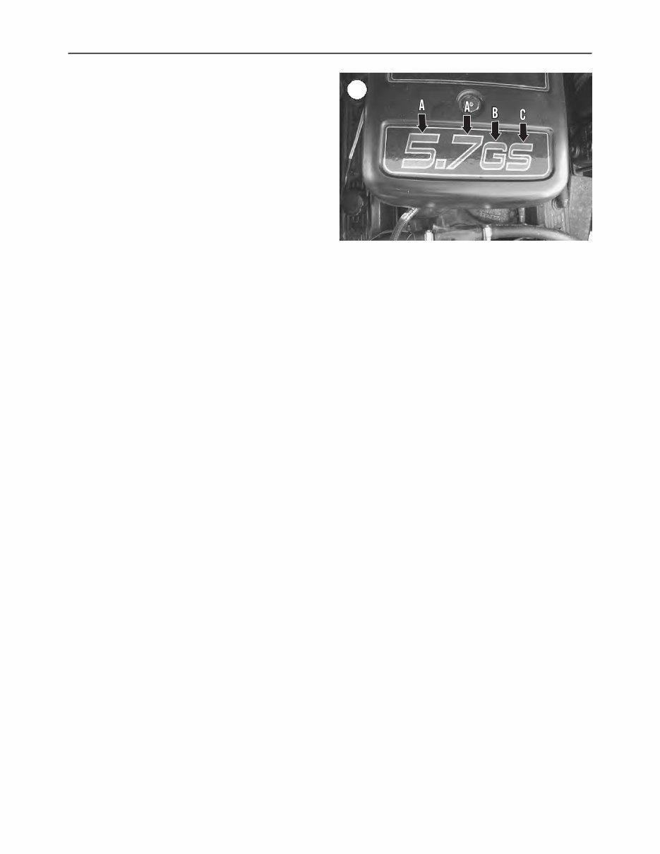
Engine model name decal
A decal on the flame arrestor cover (Figure 1) or the plas-
tic throttle body/intake cover on 5.0L and 5.8L Ford EFI
models identifies the engine model name. The numbers on
the decal (A, Figure 1) indicate the engine displacement in
liters and tenths of a liter. The first letter following the num-
bers (B, Figure 1) indicates the source of the base engine.
The letter G is used for General Motors (GM) base engines,
and the letter F is used for Ford base engines. The letter fol-
lowing the G or F (C, Figure 1) identifies the version of the
model. An I indicates the engine uses an electronic fuel in-
jection (EFI) system. An L indicates the engine is the lower
output version of the indicated displacement. An S indi-
cates the standard or higher output version of the indicated
displacement.
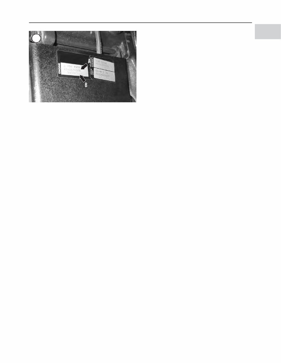
Engine identification tag
The engine identification tag (Figure 2, typical) is lo-
cated on the rocker arm cover, fuse and circuit breaker
housing, or ignition system mounting bracket (Ford EFI
GENERAL INFORMATION 3
1
2
models). This tag includes the model identification number
and engine serial number.
The model identification number (A, Figure 2) consists
of nine characters. The first two numbers indicate the en-
gine displacement in liters and tenths of a liter. For exam-
ple, the number 57 would indicate the engine displaces 5.7
liters.
The character following the displacement identification
numbers indicates the type of fuel system used on the en-
gine. The fourth character indicates the engine version and
is used to identify models produced with lower or higher
power output for the given displacement. The fifth charac-
ter is a letter that indicates whether the engine is produced
as an OMC Cobra SX engine or Volvo Penta SX engine.
The sixth character indicates the type of steering system on
the engine. The seventh and eighth characters are letters
that indicate the model year of the engine. The final charac-
ter is a letter that indicates the production version for the
given model year. The production version always starts
with an A for each model year. The letter changes to B, C
and so on as changes occur during the production year. The
model year version letter is very important when ordering
parts and servicing the engine.
Before servicing the engine or ordering replacement
parts, compare the model identification number with the in-
formation in Table 6 to correctly identify the engine.
The serial number on the identification tag (B, Figure 2)
is unique to the engine and identifies the engine from other
engines of the same model. Some states require this number
for registration and title of the vessel. The serial number
might also be required when ordering parts and servicing
the engine.
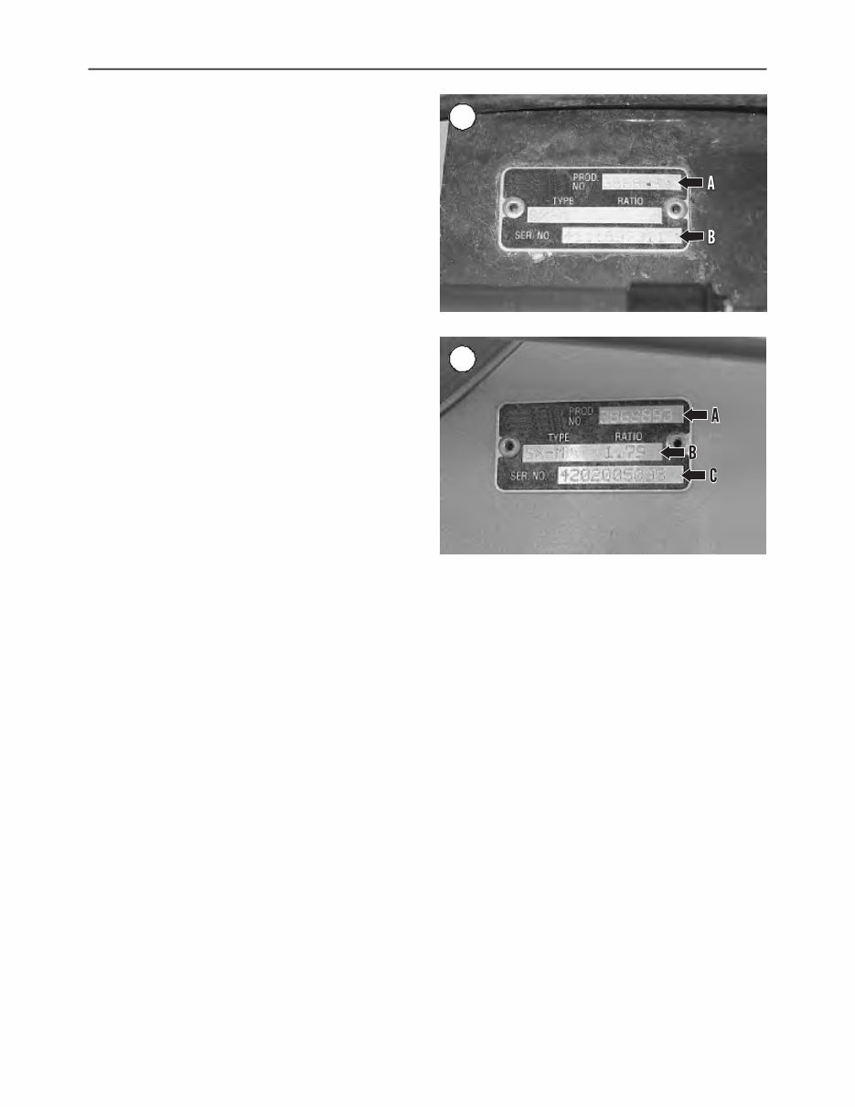
Transom bracket identification tag
The transom bracket identification tag (Figure 3, typical)
is affixed to the inner transom plate and above the steering
cable connection point. The tag lists the seven-digit tran-
som bracket model number (A, Figure 3) and the serial
number (B) unique to the transom bracket. Some states re-
quire the number for registration and title of the vessel. The
serial number might also be required when ordering parts
and servicing the transom bracket. A decal listing the infor-
mation on the transom bracket identification tag may be lo-
cated next to the engine identification tag. The decal is
supplied with the transom plate and is applied next to the
engine tag during the original engine installation. This tag
is useful when boat structure limits access to the inner tran-
som plate.
Drive unit identification tag
The drive unit identification tag is riveted to the upper
port side of the drive unit (Figure 4). The tag lists the drive
unit model number (A, Figure 4), overall gear ratio (B) and
serial number (C) unique to the drive unit. Some states re-
quire this number for registration and title of the vessel. All
of the information on the tag must be supplied when order-
ing replacement parts for the drive unit.
NOTE
The manufacturer might make changes dur-
ing a model year. When ordering parts, al-
ways order by model and serial number. For
reference, record the model and serial num-
ber in the Quick Reference Data (QRD) sec-
tion at the front of the manual. Compare new
parts with old before purchasing them. If the
parts are not alike, have the parts manager
explain the difference and verify compatibil-
ity before installing the part.
ENGINE OPERATION
All marine engines, whether two- or four-stroke, gaso-
line or diesel, operate on the Otto cycle of intake, compres-
sion, power and exhaust phases. The models covered in this
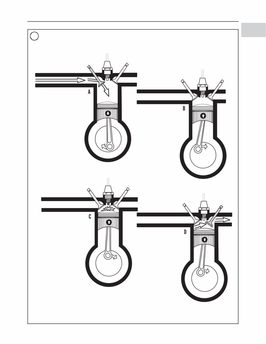
manual are a four-stroke design. Figure 5 shows typical
four-stroke gasoline engine operation.
FASTENERS
Proper fastener selection and installation is important to
make sure that the stern drive engine operates as designed
4 CHAPTER ONE
3
4
GENERAL INFORMATION 5
1
5 TYPICAL FOUR-STROKE ENGINE OPERATION
As the piston travels
downward on the intake
stroke, the exhaust valve
is closed, and the intake
valve opens and allows
the fresh air/fuel mixture
to be drawn into the
cylinder. When the piston
reaches the bottom of its
travel (BDC), the intake
valve closes and remains
closed for the next one
and one-half revolutions
of the crankshaft.
While the crankshaft
continues to rotate, the
piston moves upward in
the cylinder. Because
both valves are closed,
the piston compresses
the fresh air/fuel mixture.
When the piston nears
the top of its travel, the
spark plug fires and
ignites the compressed
air/fuel mixture to start
the power phase. Due to
crankshaft rotation, the
piston continues
movement to top dead
center (TDC) and is then
pushed downward by
expanding gasses
formed by the burning
fuel.
When the piston nears
the bottom of its travel
on the power stroke
(BDC), the exhaust
valve opens and
remains open until the
piston moves upward
and nears the top of its
exhaust stroke. The
upward travel of the
piston forces the
exhaust gasses out of
the cylinder. The
exhaust valve closes to
end the exhaust phase,
and the cycle starts all
over again.
You're Reading a Preview
What's Included?
 Lifetime Access
Fast Download Speeds
Online & Offline Access
Access PDF Contents & Bookmarks
Full Search Facility
Print one or all pages of your manual
$41.99
1994-2000 OMC Cobra SX & DP-S Duoprop Stern Drives Service & Repair Manual
Viewed 44 Times Today

What's Included?
Lifetime Access
Fast Download Speeds
Online & Offline Access
Access PDF Contents & Bookmarks
Full Search Facility
Print one or all pages of your manual
$41.99

Secure transaction
What's Included?
Lifetime Access
Fast Download Speeds
Online & Offline Access
Access PDF Contents & Bookmarks
Full Search Facility
Print one or all pages of your manual
Description
This complete workshop service repair manual for OMC Cobra SX & DP-S Duoprop Stern Drives covers every service and repair procedure needed for models from 1994 to 2000. It includes easy-to-follow step-by-step instructions and pictures for all areas of servicing and repairs, making it useful for both professional mechanics and DIY enthusiasts.
- Models covered: All models/engines/trim/transmissions types
- Contents: This high-quality manual covers all repair procedures A-Z, including every repair and service procedure
- Computer requirements: This manual is compatible with all PC & MAC computers, tablets, and mobile phones. The only software needed is Adobe Reader, which is usually pre-installed or can be downloaded for free
- Delivery: The manual will be instantly emailed to the address used during checkout after receiving payment by Visa, MasterCard, or PayPal
With this manual, you can save money by performing your own repairs and have the convenience of printing out specific pages or chapters. It's also possible to store it on your tablet or smartphone for easy access whenever needed. Customer satisfaction is guaranteed with this comprehensive manual.


