

Yanmar SD40 SD50 Sail Drive Unit Repair Service Manual - IMPROVED -
What's Included?
Fast Download Speeds
Online & Offline Access
Access PDF Contents & Bookmarks
Full Search Facility
Print one or all pages of your manual


History of Correction
Document No. M2215-04E140
Page No. 1
Manual Name: YANMAR SERVICE MANUAL FOR SAIL DRIVE UNIT SD40/SD40-4T & SD50/SD50-4T
UNIT Model: SD40/SD40-4T, SD50/SD50-4T
No.of
Correction
Date of
Correction
Cause for
Correction
Outline of
Correction
Corrected Item
Number
Corrected
by:
- Mar. 2005 Added SD50/-4T (1) Added SD50
series.
(2) Changed doc-
ument num-
ber.
M9961-H13030
M2215-04E140
- Quality Control
Dept.
Marine factory

1 General ............................................................................................................................................................ 1
1.1 Specifications ........................................................................................................................................... 1
1.2 Exterior view ............................................................................................................................................. 2
1.3 Sectional view .......................................................................................................................................... 3
1.4 Criteria for replacing parts ........................................................................................................................ 4
1.5 Route of cooling water and lubricating oil ................................................................................................ 5
1.6 Lubricating oil ........................................................................................................................................... 6
1.7 Disassembly and reassembly .................................................................................................................. 7
1.8 Special tools ........................................................................................................................................... 14
1.9 Notes on disassembly, inspection and reassembly ............................................................................... 19
2 Disassembly ................................................................................................................................................... 20
2.1 Disassembling the upper case ............................................................................................................... 20
2.1.1 Removal of the unit ...................................................................................................................... 20
2.1.2 Disassembling the unit ................................................................................................................. 27
2.2 Disassembling the lower case ................................................................................................................ 32
2.2.1 Removal of unit ............................................................................................................................ 32
3 Reassembly ................................................................................................................................................... 38
3.1 Reassembling the bearing for lower case .............................................................................................. 38
3.1.1 Needle bearing ............................................................................................................................ 38
3.1.2 Taper roller bearing outer race .................................................................................................... 38
3.2 Reassembling the bearings of shaft ....................................................................................................... 39
3.2.1 Propeller shaft .............................................................................................................................. 39
3.2.2 Drive shaft .................................................................................................................................... 39
4 Shim adjustment (Gear backlash adjustment) ............................................................................................... 40
4.1 Location of adjustment shims ................................................................................................................. 40
4.2 Measurement of the dimensions of the cases ........................................................................................ 41
4.2.1 Upper case .................................................................................................................................. 41
4.2.2 Lower case ....................................................................... 41
4.3 Shim selection method for the clutch shaft ............................................................................................ 42
4.3.1 Measurement of the dimensions (L1, L2, L3) of the gear ............................................................ 42
4.3.2 Calculation of the shim thickness ................................................................................................ 43
4.4 Shim selection method for the pinion shaft ............................................................................................ 44
4.4.1 Measurement of the pinion dimensions ....................................................................................... 44
4.4.2 Calculation of the shim thickness ................................................................................................ 44
4.5 Shim selection method for the drive shaft .............................................................................................. 45
4.5.1 Measurement of the dimensions (M1) of the pinion ..................................................................... 45
4.5.2 Calculation of the shim thickness ................................................................................................ 45
CONTENTS

4.6 Shim selection method for the propeller shaft ........................................................................................ 46
4.6.1 Measurement of the dimensions (M3) of the gear ....................................................................... 46
4.6.2 Calculation of the shim thickness ................................................................................................ 46
5 Adjustment of bearing assembly gap ............................................................................................................. 47
5.1 Upper gear bearing ................................................................................................................................ 47
5.1.1 Measurement of the dimension (L6) of the bearing ..................................................................... 47
5.1.2 Calculation of the shim thickness ................................................................................................ 47
5.2 Pinion shaft bearing ............................................................................................................................... 48
5.2.1 Measurement of the dimension (L4) of the bearing ..................................................................... 48
5.2.2 Calculation of the shim thickness ................................................................................................ 48
5.3 Pinion drive shaft bearing ....................................................................................................................... 49
5.3.1 Measurement of the dimension (M2) of the bearing .................................................................... 49
5.3.2 Calculation of the shim thickness ................................................................................................ 49
5.4 Propeller shaft bearing ........................................................................................................................... 50
5.4.1 Measurement of the dimension (M4) of the bearing .................................................................... 50
5.4.2 Calculation of the shim thickness ................................................................................................ 50
6 Adjustment of the gear backlash .................................................................................................................... 51
6.1 Upper gear ............................................................................................................................................. 51
6.2 Lower gear ............................................................................................................................................. 52
7 Adjustment of the gear dye pattern ................................................................................................................ 53
7.1 Upper gear ............................................................................................................................................. 53
7.2 Propeller shaft ........................................................................................................................................ 54
8 Adjustment of the shift lever ........................................................................................................................... 55
8.1 Measurement of the dimensions (H, A) .................................................................................................. 55
8.1.1 Shift Lever bolt ..................................................................... 55
8.1.2 Shifter pin position ....................................................................................................................... 55
8.2 Calculation of the shim thickness ........................................................................................................... 56
8.3 Caution of reassembly ........................................................................................................................... 56
9 Tightening torque for nuts and bolts ............................................................................................................... 57

FOR SAFETY
1. SAFETY LABELS
• Most accidents are caused by negligence of basic safety rules and precautions. For accident
prevention, it is important to avoid such causes before development to accidents.
Please read this manual carefully before starting repair or maintenance to fully understand safety
precautions and appropriate inspection and maintenance procedures.
Attempting at a repair or maintenance job without sufficient knowledge may cause an unexpected
accident.
• It is impossible to cover every possible danger in repair or maintenance in the manual. Sufficient
consideration for safety is required in addition to the matters marked . Especially for
safety precautions in a repair or maintenance job not described in this manual, receive instructions
from a knowledgeable leader.
• Safety marks used in this manual and their meanings are as follows:
DANGER-indicates an imminent hazardous situation which, if
not avoided, WILL result in death or serious injury.
WARNING-indicates a potentially hazardous situation which, if
not avoided, COULD result in death or serious injury.
CAUTION-indicates a potentially hazardous situation which, if
not avoided, may result in minor or moderate injury.
• NOTICE - indicates that if not observed, the product performance or quality may not be
guaranteed.

2. Safety Precautions
(1) SERVICE AREA
• Sufficient Ventilation
Inhalation of exhaust fumes and dust particles may be hazardous to ones
health. Running engines welding, sanding, painting, and polishing tasks
should be only done in well ventilated areas.
• Safe / Adequate Work Area
The service area should be clean, spacious, level and free from holes in
the floor, to prevent "slip" or "trip and fall" type accidents.
• Clean, orderly arranged place
No dust, mud, oil or parts should be left on the floor surface.
[Failure to Observe]
An unexpected accident may be caused.
• Bright, Safely Illuminated Area
The work area should be well lit or illuminated in a safe manner. For work
in enclosed or dark areas, a "drop cord" should be utilized. The drop cord
must have a wire cage to prevent bulb breakage and possible ignition of
flammable substances.
• Safety Equipment
Fire extinguisher(s), first aid kit and eye wash / shower station should be
close at hand (or easily accessible) in case of an emergency.
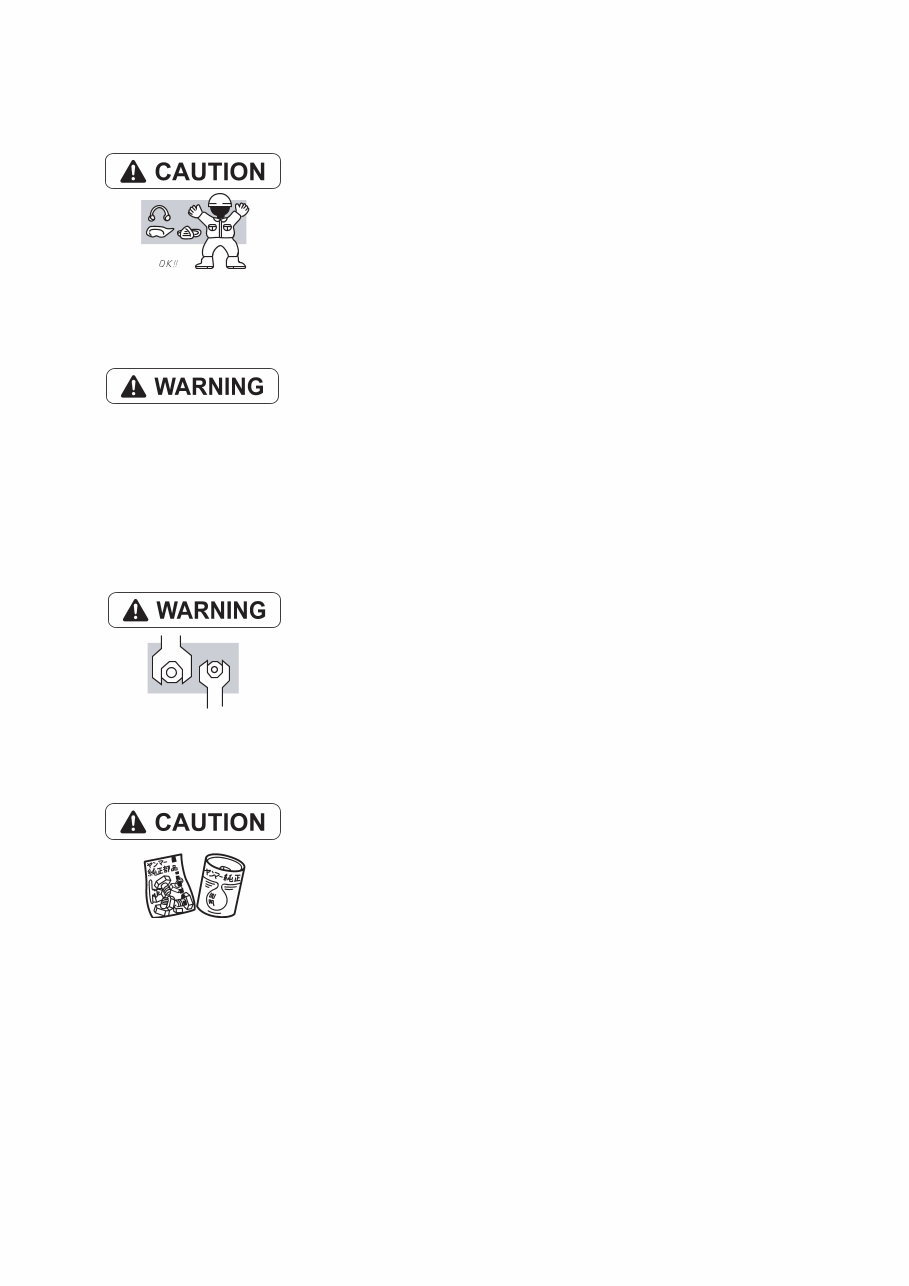
(2) WORK - WEAR (GARMENTS)
• Safe Work Clothing
Appropriate safety wear (gloves, special shoes/boots, eye/ear protection,
head gear, harness', clothing, etc.) should be used/worn to match the task
at hand. Avoid wearing jewelry, unbuttoned cuffs, ties or loose fitting
clothes around moving machinery. A serious accident may occur if caught
in moving/rotating machinery.
(3) TOOLS
• Appropriate Lifting / Holding
When lifting an engine, use only a lifting device (crane, jack, etc.) with
sufficient lifting capacity. Do not overload the device. Use only a chain,
cable, or lifting strap as an attaching device. Do not use rope, serious
injury may result.
To hold or support an engine, secure the engine to a support stand, test
bed or test cart designed to carry the weight of the engine. Do not
overload this device, serious injury may result.
Never run an engine without being properly secured to an engine support
stand, test bed or test cart, serious injury may result.
• Appropriate Tools
Always use tools that are designed for the task at hand. Incorrect usage
of tools may result in damage to the engine and or serious personal injury.
(4) GENUINE PARTS and MATERIALS
• Genuine Parts
Always use genuine YANMAR parts or YANMAR recommended parts and
goods. Damage to the engine, shortened engine life and or personal
injury may result.
Well fitting !!
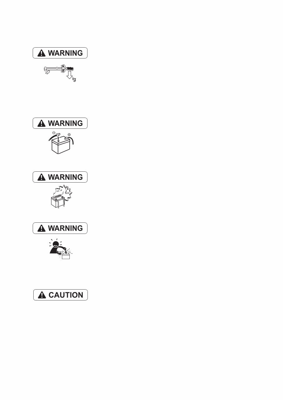
(5) FASTENER TORQUE
• Torquing Fasteners
Always follow the torque values and procedures as designated in the
service manual. Incorrect values, procedures and or tools may cause
damage to the engine and or personal injury.
(6) Electrical
• Short Circuits
Always disconnect the (-) Negative battery cable before working on the
electrical system. An accidental "short circuit" may cause damage, fire
and or personal injury. Remember to connect the (-) Negative battery
cable (back onto the battery) LAST
• Charging Batteries
Charging wet celled batteries produces hydrogen gas. Hydrogen gas is
extremely explosive. Keep sparks, open flame and any other form of
ignition away. Explosion may occur causing severe personal injury.
• Battery Electrolyte
Batteries contain sulfuric acid. Do NOT allow it to come in contact with
clothing, skin and or eyes, severe burns will result.
(7) WASTE MANAGEMENT
Observe the following instructions with regard to hazardous waste
disposal. Negligence of these will have a serious impact on environmental
pollution concerns.
1) Waste fluids such as lube oil, fuel and coolant shall be carefully put
into separate sealed containers and disposed of properly.
2) Do NOT dispose of waste materials irresponsibly by dumping them
into the sewer, overland or into natural waterways.
3) Waste materials such as oil, fuel, coolant, solvents, filter elements and
batteries, must be disposed of properly according to local ordinances.
Consult the local authorities or reclamation facility.
(8) FURTHER PRECAUTIONS
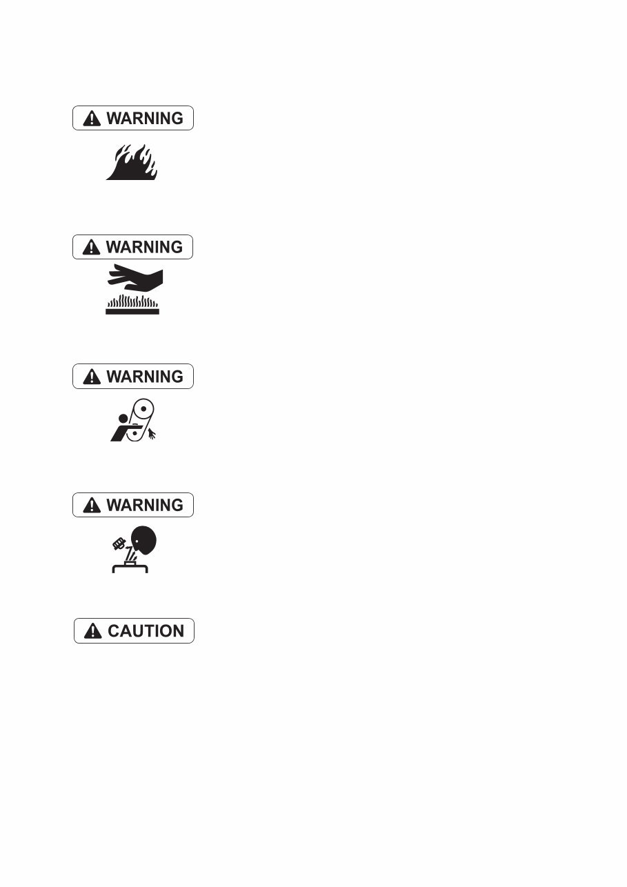
• Fueling / Refueling
Keep sparks, open flames or any other form of ignition (match, cigarette,
etc.) away when fueling/refueling the unit. Fire and or an explosion may
result.
• Hot Surfaces.
Do NOT touch the engine (or any of its components) during running or
shortly after shutting it down. Scalding / serious burns may result. Allow
the engine to cool down before attempting to approach the unit.
• Rotating Parts
Be careful around moving/rotating parts. Loose clothing, jewelry, ties or
tools may become entangled causing damage to the engine and or
severe personal injury.
• Preventing burns from scalding
1) Never open the filler cap shortly after shutting the engine down.
Steam and hot water will spurt out and seriously burn you. Allow the
engine to cool down before attempt to open the filler cap.
2) Securely tighten the filler cap after checking the cooling water.
Steam can spurt out during engine running, if tightening loose.
• Safety Label Check
Pay attention to the product safety label.
A safety label (caution plate) is affixed on the product for calling special
attention to safety.
If it is missing or illegible, always affix a new one.

3. Precautions for Service Work
(1) Precautions for Safety
Read the safety precautions given at the beginning of this manual carefully and always mind safety in
work.
(2) Preparation for Service Work
Preparation is necessary for accurate, efficient service work. Check the customer ledger file for the
history of the engine.
• Preceding service date
• Period/operation hours after preceding service
• Problems and actions in preceding service
• Replacement parts expected to be required for service
• Recording form/check sheet required for service
(3) Preparation before Disassembly
• Prepare general tools, special service tools, measuring instruments, oil, grease, non-reusable parts,
and parts expected to be required for replacement.
• When disassembling complicated portions, put match-marks and other marks at places not
adversely affecting the function for easy reassembly.
(4) Precautions in Disassembly
• Each time a parts is removed, check the part installed state, deformation, damage, roughening,
surface defect, etc.
• Arrange the removed parts orderly with clear distinction between those to be replaced and those to
be used again.
• Parts to be used again shall be washed and cleaned sufficiently.
• Select especially clean locations and use clean tools for disassembly of hydraulic units such as the
fuel injection pump.
(5) Precautions for Inspection and Measurement
Inspect and measure parts to be used again as required to determine whether they are reusable or not.
(6) Precautions for Reassembly
• Reassemble correct parts in correct order according to the specified standards (tightening torques,
and adjustment standards). Apply oil important bolts and nuts before tightening when specified.
• Always use genuine parts for replacement.
• Always use new oil seals, O-rings, packing and cotter pins.
• Apply sealant to packing depending on the place where they are used. Apply of grease to sliding
contact portions, and apply grease to oil seal lips.
(7) Precautions for Adjustment and Check
Use measuring instruments for adjustment to the specified service standards.
You're Reading a Preview
What's Included?
Fast Download Speeds
Online & Offline Access
Access PDF Contents & Bookmarks
Full Search Facility
Print one or all pages of your manual
$31.99
Viewed 42 Times Today


Secure transaction
What's Included?
Fast Download Speeds
Online & Offline Access
Access PDF Contents & Bookmarks
Full Search Facility
Print one or all pages of your manual
$31.99
- This Complete Factory Yanmar Models SD40, SD40-4T, SD50 and SD50-4T Sail Drive Unit Repair Service Manual provides detailed instructions for maintaining and servicing your Sail Drive, including comprehensive illustrations, exploded diagrams, drawings, and photos.
- IMPROVED manuals have: Bookmarks, Searchable Text, Indexed, and Improved Quality.
- Models Covered:
- SD40-3
- SD50-3
- SD40-4
- SD50-4
- SD40-4T
- SD50-4T
- INSTANT - NO WAITING
- LANGUAGE: English
- FORMAT: .PDF
- COMPATIBLE: All Versions of Windows & Mac
- SEARCHABLE - BOOKMARKED - INDEXED
- Navigation is simple with chapter bookmarks and the ability to search by keyword.
- Print out the entire manual or just the sections you'll be working on.
- CONTENTS:
- Safety
- General
- Disassembly
- Reassembly
- Shim Adjustment (Gear Backlash Adjustment)
- Adjustment of Bearing Assembly Gap
- Adjustment of the Gear Backlash
- Adjustment of the Gear Dye Pattern
- Adjustment of the Shift Lever
- Inspection & Servicing
- Tightening Torques for Nuts & Bolts
- This manual is perfect for tune-ups, regular maintenance, and repairs, providing mechanical details and step-by-step instructions.
- Additional Information: Documents may require the newest version of Acrobat Reader to display correctly. Should you have any problems reading your document, please initially try upgrading to the latest version of Adobe Acrobat Reader.
- I have Thousands of Manuals - email me about any you might need.


