

2004 Yamaha 90TLRC Outboard Service & Repair Manual
What's Included?
Fast Download Speeds
Online & Offline Access
Access PDF Contents & Bookmarks
Full Search Facility
Print one or all pages of your manual

60C
70C
90C
SERVICE MANUAL
6H2-28197-1F-11 LIT-18616-02-66
*LIT186160266*

E
NOTICE
This manual has been prepared by Yamaha primarily for use by Yamaha dealers and their
trained mechanics when performing maintenance procedures and repairs to Yamaha equip-
ment. It has been written to suit the needs of persons who have a basic understanding of the
mechanical and electrical concepts and procedures inherent in the work, for without such
knowledge attempted repairs or service to the equipment could render it unsafe or unfit for
use.
Because Yamaha has a policy of continuously improving its products, models may differ in
detail from the descriptions and illustrations given in this publication. Use only the latest edi-
tion of this manual. Authorized Yamaha dealers are notified periodically of modifications and
significant changes in specifications and procedures, and these are incorporated in succes-
sive editions of this manual.
60C, 70C, 90C
SERVICE MANUAL
©2003 by Yamaha Motor Corporation, USA
1st Edition, October 2003
All rights reserved.
Any reprinting or unauthorized use
without the written permission of
Yamaha Motor Corporation, USA
is expressly prohibited.
Printed in USA
LIT-18616-02-66
E
A50000-0
HOW TO USE THIS MANUAL
MANUAL FORMAT
This manual provides the mechanic with descriptions of the operations of disassembly,
repair, assembly, adjustment and inspection, each of which is presented in a sequential, step-
by-step procedure.
To assist you to find your way about this manual, the Section Title and Major Heading is
given at the head of every page.
An Index to contents is provided on the first page of each section.
MODEL INDICATION
Multiple models are shown in this manual. These indications are noted as follows.
THE ILLUSTRATIONS
Some illustrations in this manual may differ from the model you have. This is because the
procedure described may relate to several models, though only one may be illustrated. (The
name of the model described will be mentioned in the description.)
To help you identify components and understand the correct procedures of disassembly and
assembly, exploded diagrams are provided. Steps in the procedures are numbered thus: 1),
2), 3). Parts shown in the illustrations are identified thus: 1 , 2 , 3 .
REFERENCES
These have been kept to a minimum, however, when you are referred to another section of
the manual, you are told the page number to go to.
Model name 60FETO 70BETO 90AETO
USA and
Canada name
60TR 70TR 90TR
Indication 60FETO 70BETO 90AETO
E
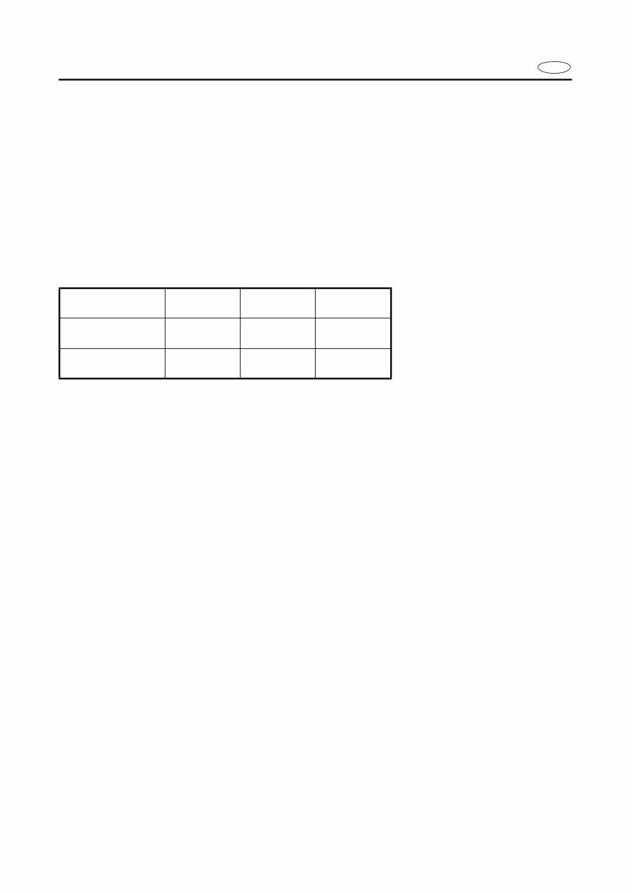
SPECIFICATIONS
These are given in bold type at each procedure. It is not necessary to leave the section deal-
ing with the procedure in order to look up the specifications.
It is important to note the differences in specifications of models. Where a procedure relates
to more than one model, the main differences in specifications will be shown in the following
table.
WARNINGS, CAUTIONS AND NOTES
Attention is drawn to the various Warnings, Cautions and Notes which distinguish important
information in this manual in the following ways.
The Safety Alert Symbol means ATTENTION! BECOME ALERT! YOUR SAFETY IS
INVOLVED!
WARNING
Failure to follow WARNING instructions could result in severe injury or death to the machine
operator, a bystander, or a person inspecting or repairing the outboard motor.
CAUTION:
A CAUTION indicates special precautions that must be taken to avoid damage to the out-
board motor.
NOTE:
A NOTE provides key information to make procedures easier or clearer.
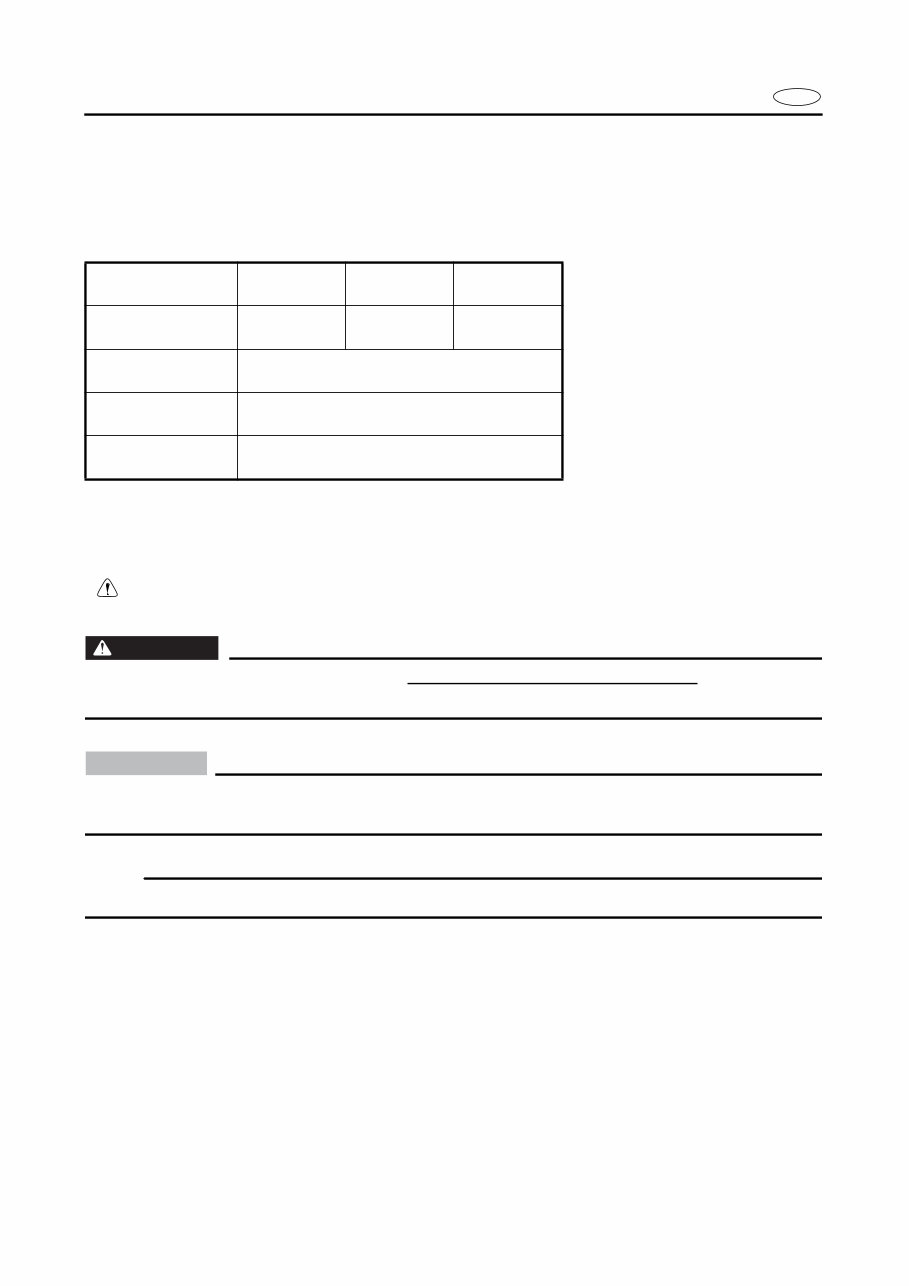
Model name 60FETO 70BETO 90AETO
USA and
Canada name
60TR 70TR 90TR
Control system Remote control
Tilt system Power trim and tilt
Lubrication
system
Oil injection
E
A50001-1-4
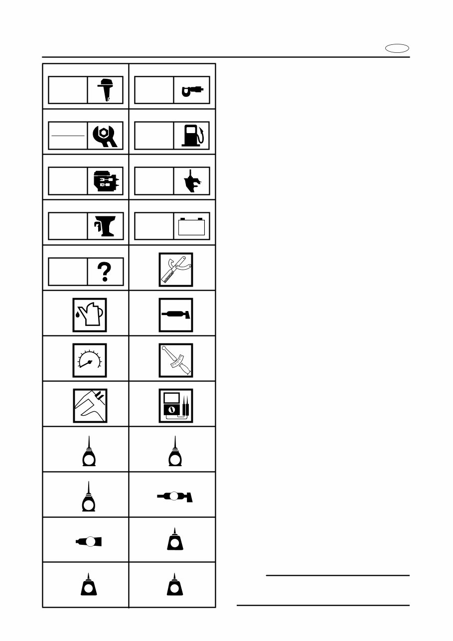
SYMBOLS
Symbols 1 to 9 are designed as thumb-
tabs to indicate the content of a chapter.
1 General Information
2 Specifications
3 Periodic Inspection and Adjustment
4 Fuel System
5 Power Unit
6 Lower Unit
7 Bracket Unit
8 Electrical Systems
9 Trouble Analysis
Symbols 0 to F indicates specific data:
0 Special service tool
A Specified liquid
B Specified grease
C Specified engine speed
D Specified torque
E Specified measurement
F Specified electrical value
[Resistance (Ω), Voltage (V),
Electric current (A)]
Symbol G to J in an exploded diagram
indicate grade of lubricant and location of
lubrication point:
G Apply engine oil
H Apply gear oil
I Apply molybdenum disulfide oil
J Apply water resistant grease (Yamaha
marine grease A, Yamaha marine grease)
Symbols K to N in an exploded diagram
indicate grade of sealing or locking agent,
and location of application point:
K Apply Gasket Maker
®
L Apply LOCTITE
®
No. 271 (Red LOCTITE)
M Apply LOCTITE
®
No. 242 (Blue LOCTITE)
N Apply LOCTITE
®
No. 572
NOTE:
In this manual, the above symbols may not
be used in every case.
1 2
3 4
5 6
7 8
9 0
A B
C D
E F
G H
I J
K L
M N
GEN
INFO
SPEC
INSP
ADJ
FUEL
POWR LOWR
BRKT
– +
ELEC
TRBL
ANLS
T
R
.
.
E G
M
A
GM
271
LT
242
LT
572
LT
E
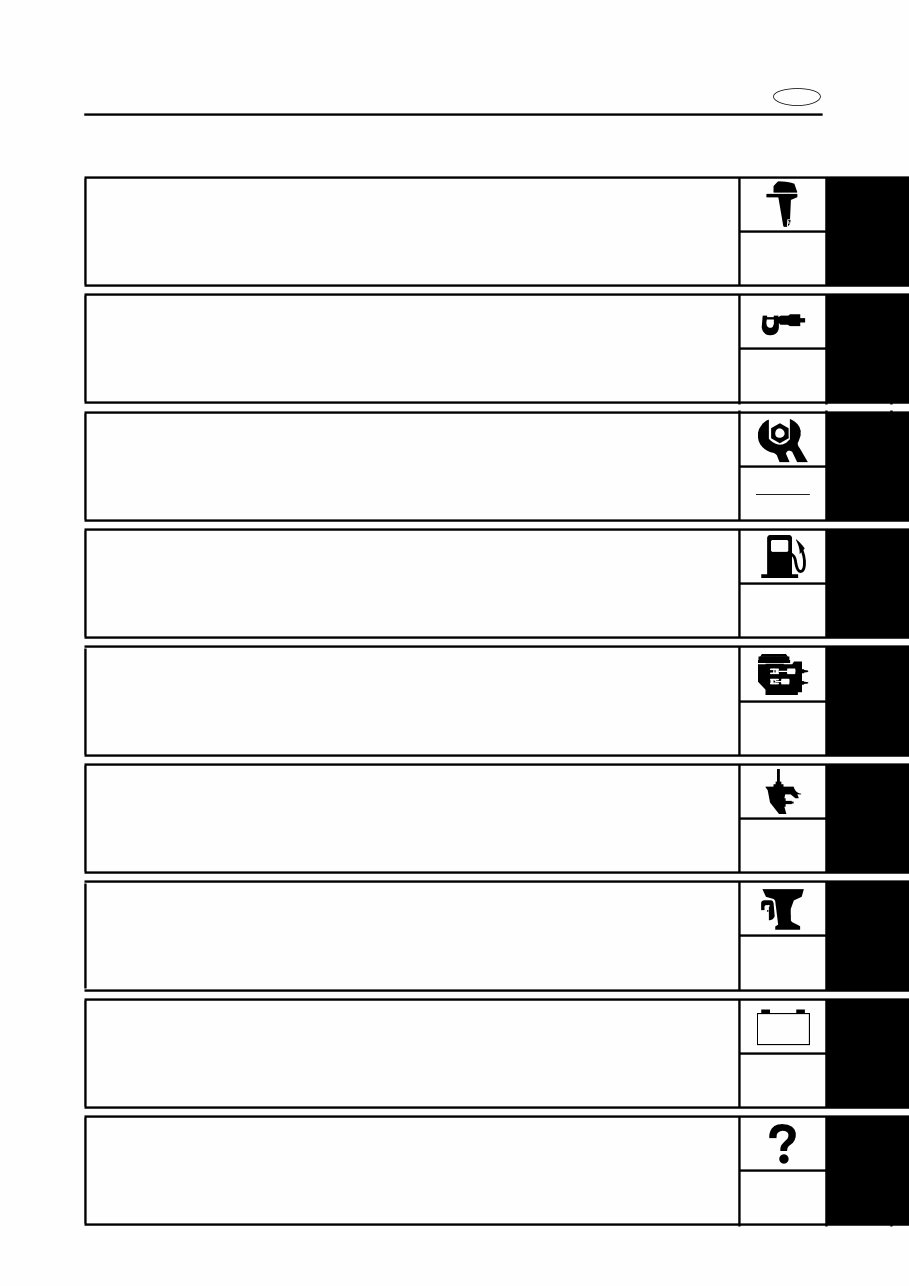
INDEX
GENERAL INFORMATION
1
SPECIFICATIONS
2
SPEC
PERIODIC INSPECTION AND
ADJUSTMENT
3
FUEL SYSTEM
4
FUEL
POWER UNIT
5
POWR
LOWER UNIT
6
LOWR
BRACKET UNIT
7
BRKT
ELECTRICAL SYSTEMS
8
ELEC
TROUBLE ANALYSIS
9
GEN
INFO
INSP
ADJ
– +
TRBL
ANLS
A30000-0
E
1
2
3
4
5
6
7
8
9
GEN
INFO
CHAPTER 1
GENERAL INFORMATION
IDENTIFICATION ............................................................................................ 1-1
SERIAL NUMBER ..................................................................................... 1-1
STARTING SERIAL NUMBERS ............................................................... 1-1
SAFETY WHILE WORKING ............................................................................ 1-2
FIRE PREVENTION ................................................................................... 1-2
VENTILATION........................................................................................... 1-2
SELF-PROTECTION.................................................................................. 1-2
OILS, GREASES AND SEALING FLUIDS................................................ 1-2
GOOD WORKING PRACTICES ................................................................ 1-3
DISASSEMBLY AND ASSEMBLY ........................................................... 1-4
SPECIAL TOOLS ............................................................................................. 1-5
MEASURING ............................................................................................ 1-6
REMOVAL AND INSTALLATION ............................................................ 1-8
1-1
GEN
INFO
E
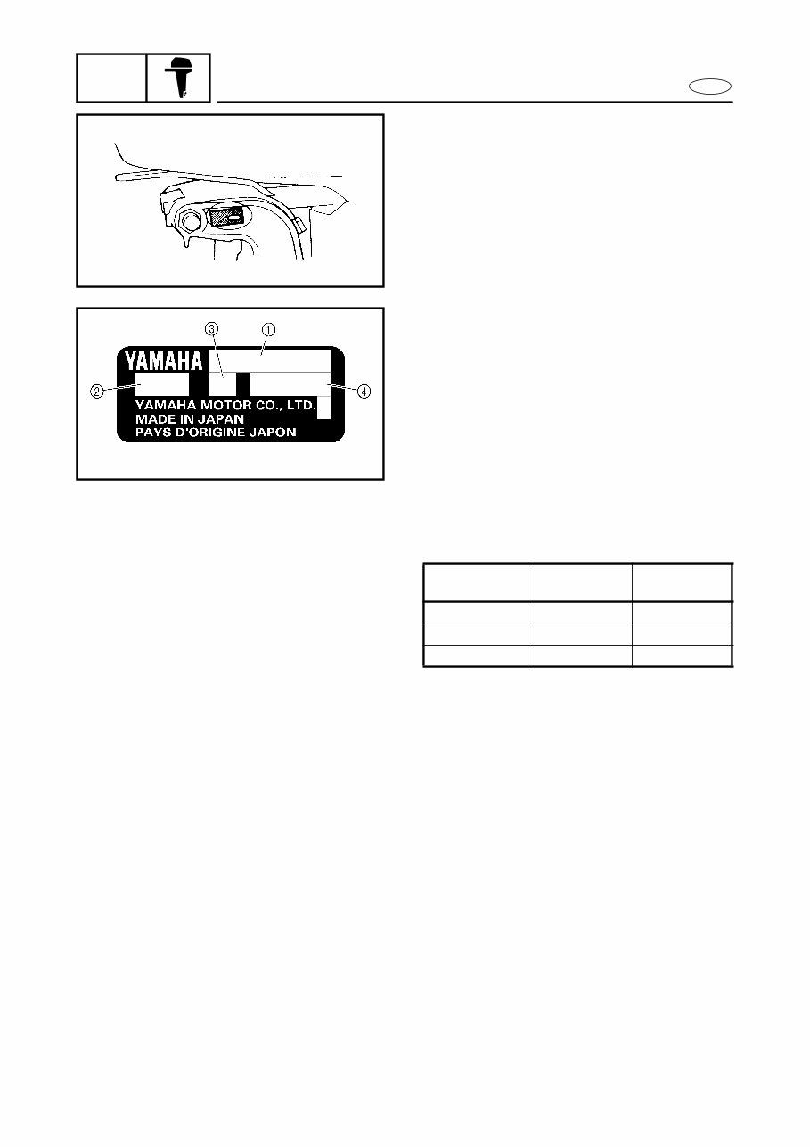
IDENTIFICATION
A60000-1*
IDENTIFICATION
SERIAL NUMBER
The outboard motor serial number is
stamped on a label attached to the port
clamp bracket.
1 Model name
2 Approved model code
3 Transom height
4 Serial number
STARTING SERIAL NUMBERS
The starting serial number blocks are as fol-
lows:
Model name
Approved
model code
Starting
serial No.
60TR 6H2 L: 1003093 ~
70TR 6H3 L: 1002818 ~
90TR 6H1 L: 1007591 ~
1-2
GEN
INFO
E
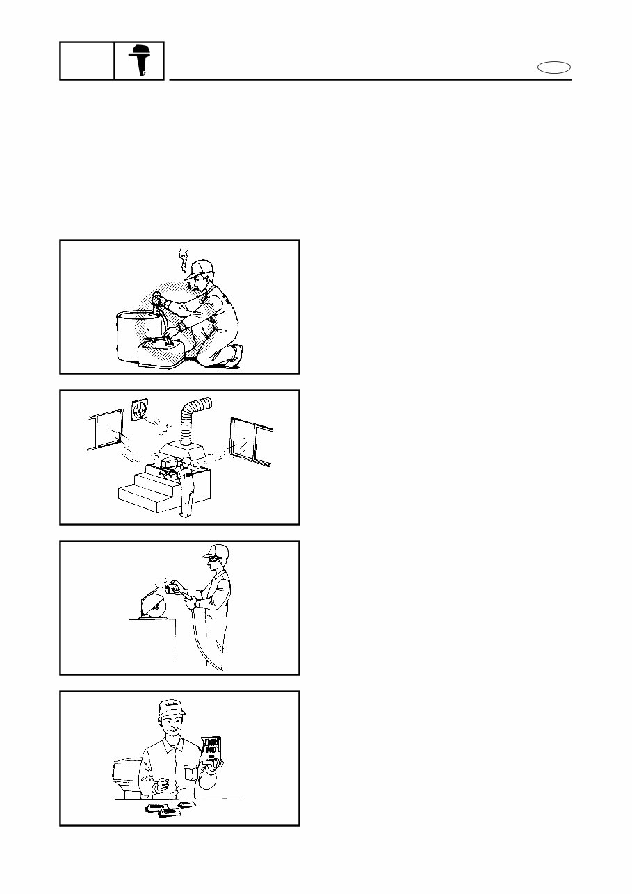
SAFETY WHILE WORKING
SAFETY WHILE WORKING
The procedures given in this manual are
those recommended by Yamaha to be fol-
lowed by Yamaha dealers and their
mechanics.
FIRE PREVENTION
Gasoline (petrol) is highly flammable.
Petroleum vapor is explosive if ignited.
Do not smoke while handling and keep it
away from heat, sparks, and open flames.
VENTILATION
Petroleum vapor is heavier than air and if
inhaled in large quantities will not support
life. Engine exhaust gases are harmful to
breathe. When test-running an engine
indoors, maintain good ventilation.
SELF-PROTECTION
Protect your eyes with suitable safety
glasses or safety goggles when using com-
pressed air, when grinding or when doing
any operation which may cause particles to
fly off.
Protect hands and feet by wearing safety
gloves or protective shoes if appropriate to
the work you are doing.
OILS, GREASES AND SEALING
FLUIDS
Use only genuine Yamaha oils, grease and
sealing fluids or those recommended by
Yamaha.
1-3
GEN
INFO
E
SAFETY WHILE WORKING
Under normal conditions of use, there
should be no hazards from the use of the
lubricants mentioned in this manual. How-
ever, safety is all-important and by adopt-
ing good safety practices, any risk is
minimized.
A summary of the most important precau-
tions is as follows:
1. While working, maintain good stan-
dards of personal and industrial
hygiene.
2. Clothing which has become contami-
nated with lubricants should be
changed as soon as practicable, and
laundered before further use.
3. Avoid skin contact with lubricants; do
not, for example, place a soiled wiping-
rag in one’s pocket.
4. Hands, and any other part of the body
which have been in contact with lubri-
cants or lubricant-contaminated cloth-
ing, should be thoroughly washed with
hot water and soap as soon as practica-
ble.
5. To protect the skin, the application of a
suitable barrier cream to the hands
before working is recommended.
6. A supply of clean, lint-free cloths should
be available for wiping purposes.
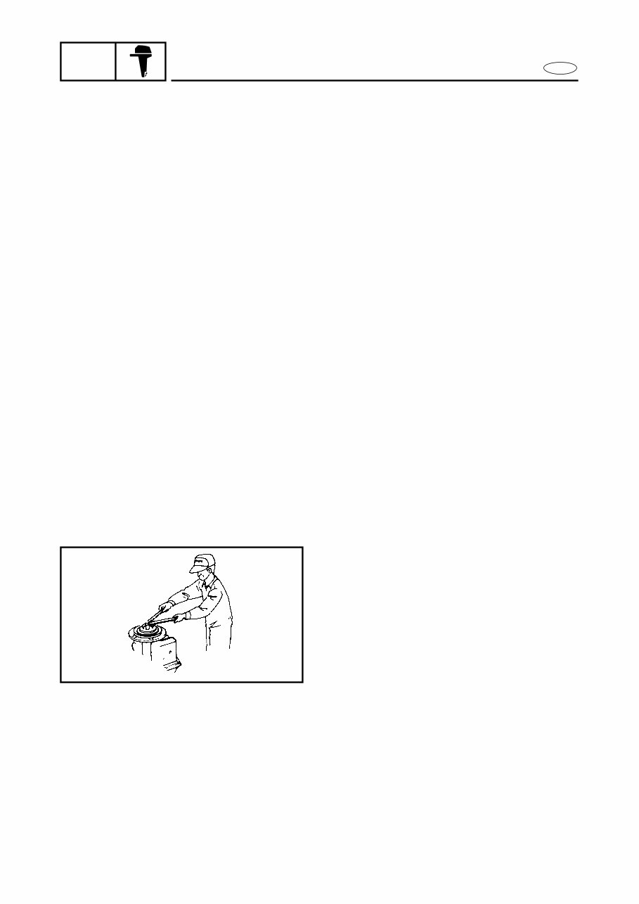
GOOD WORKING PRACTICES
1. The right tools
Use the special tools that are advised to
protect parts from damage. Use the
right tool in the right manner - don’t
improvise.
2. Tightening torque
Follow the torque tightening instruc-
tions. When tightening bolts, nuts and
screws, tighten the larger sizes first, and
tighten inner-positioned fixings before
outer-positioned ones.
You're Reading a Preview
What's Included?
Fast Download Speeds
Online & Offline Access
Access PDF Contents & Bookmarks
Full Search Facility
Print one or all pages of your manual
$35.99
Viewed 69 Times Today


Secure transaction
What's Included?
Fast Download Speeds
Online & Offline Access
Access PDF Contents & Bookmarks
Full Search Facility
Print one or all pages of your manual
$35.99
- This repair manual provides troubleshooting and replacement procedures for the 2004 Yamaha 90TLRC Outboard, including step-by-step instructions, clear images, and exploded-view illustrations.
- It is useful for both professional mechanics and DIY enthusiasts for maintaining and repairing the outboard.
- Regular maintenance and eventual part replacement are inevitable for any outboard, and this manual offers manufacturer-recommended troubleshooting charts and replacement procedures to ensure proper maintenance.
- With this manual, you can save on repairs, increase the outboard’s reliability, and effectively address issues.
- The manual is available in .pdf format and is printable. It contains every service and repair procedure provided by the manufacturer, including step-by-step instructions, exploded-view illustrations, and clear images.
- It is compatible with various electronic devices such as PC, Mac computers, Android and Apple smartphones, and tablets. Adobe Reader is required for viewing.
No need to flip through hundreds of pages to find specific information; no more greasy, torn, or lost pages anymore! Carry them around, search them, screenshot them, bookmark them — much better than a traditional bound manual if you ask me. Of course, if you prefer to have a physical copy, nothing prevents you from printing it out too.


