LIT186160183 SERVICE MANUAL LIT-18616-01-83 290328 WORLD WIDE F8B FT9.9A F9.9B USA, CANADA T9.9W F9.9W
E A20000-1 NOTICE This manual has been prepared by the Yamaha Motor Company Ltd. primarily for use by Yamaha dealers and their trained mechanics when performing maintenance procedures and repairs to Yamaha equipment. It has been written to suit the needs of persons who have a basic understanding of the mechanical and electrical concepts and procedures inherent in the work, for without such knowledge attempted repairs or service to the equipment could render it unsafe or unfit for use. Because the Yamaha Motor Company Ltd. has a policy of continuously improving its prod- ucts, models may differ in detail from the descriptions and illustrations given in this publica- tion. Use only the latest edition of this manual. Authorized Yamaha dealers are notified periodically of modifications and significant changes in specifications and procedures, and these are incorporated in successive editions of this manual. A10001-0* T9.9, F9.9 SERVICE MANUAL 1997 Yamaha Motor Corporation, USA 1st Edition, September 1997 All rights reserved. No part of this publication may be reproduced or transmitted in any form or by any means including photocopying and recording without the written permission of the copyright holder. Such written permission must also be obtained before any part of this publication is stored in a retrieval system of any nature. Printed in USA P/N LIT-18616-01-83
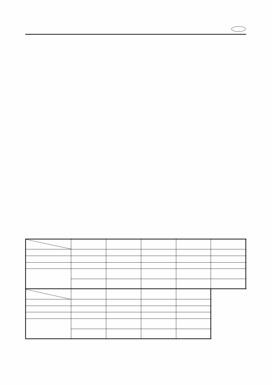
E HOW TO USE THIS MANUAL MANUAL FORMAT All of the procedures in this manual are organized in a sequential, step-by-step format. The information has been compiled to provide the mechanic with an easy to read, handy refer- ence that contains comprehensive explanations of all disassembly, repair, assembly, and inspection operations. In this revised format, the condition of a faulty component will precede an arrow symbol and the course of action required will follow the symbol, e.g., ● Bearing Pitting/Damage → Replace. To assist you to find your way about this manual, the Section Title and Major Heading is given at the head of every page. An Index to contents is provided on the first page of each section. THE ILLUSTRATIONS Some illustrations in this manual may differ from the model you have. This is because a pro- cedure described may relate to several models, though only one may be illustrated. (The name of the model described will be mentioned in the description). REFERENCES Reference have been kept to a minimum; however, when you are referred to another section of the manual, you are told the page number to go to. SPECIFICATIONS These are given in bold type at each procedure. It is not necessary to have the section dealing with the procedure in order to look up the specifications. It is important to note the differences in specifications of models. Where a procedure relates to more than one model, the main differences in specifications will be shown in the following table. *1: Except for USA and Switzerland *2: For USA and Switzerland Model Item F8BMH F8BEH F8BE T9,9MH/ FT9.9AMH T9.9EH/FT9.9AEH Starting system Manual start Electric start Electric start Manual start Electric start Control system Manual control Manual control Remote control Manual control Manual control Tilt system Manual tilt Manual tilt Manual tilt Manual tilt Manual tilt Carburetor (Pilot screw) Adjustable screw *1 Adjustable screw *1 Adjustable screw *1 Adjustable screw *1 Adjustable screw *1 None adjustable screw *2 None adjustable screw *2 None adjustable screw *2 None adjustable screw *2 None adjustable screw *2 Model Item T9.9ER/FT9.9AE F9.9MH/F9.9BMH F9.9EH/F9.9BEH F9.9BE Starting system Electric start Manual start Electric start Electric start Control system Remote control Manual control Manual control Remote control Tilt system Manual tilt Manual tilt Manual tilt Manual tilt Carburetor (Pilot screw) Adjustable screw *1 Adjustable screw *1 Adjustable screw *1 Adjustable screw *1 None adjustable screw *2 None adjustable screw *2 None adjustable screw *2 None adjustable screw *2
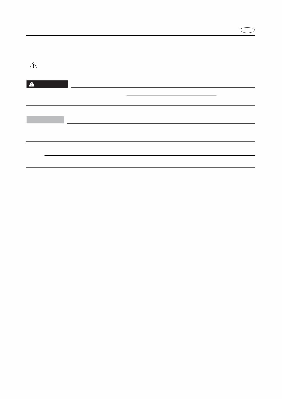
E WARNINGS, CAUTIONS AND NOTES Attention is drawn to the various Warnings, Cautions and Notes with distinguished important information in this manual in the following ways. The Safety Alert Symbol means ATTENTION! BECOME ALERT! YOUR SAFETY IS INVOLVED! WARNING Failure to follow WARNING instructions could result in severe injury or death to the machine operator, a bystander, or a person inspecting or repairing the outboard motor. CAUTION: A CAUTION indicates special precautions that must be taken to avoid damage to the out- board motor. NOTE: A NOTE provides key information to make procedures easier or clearer.
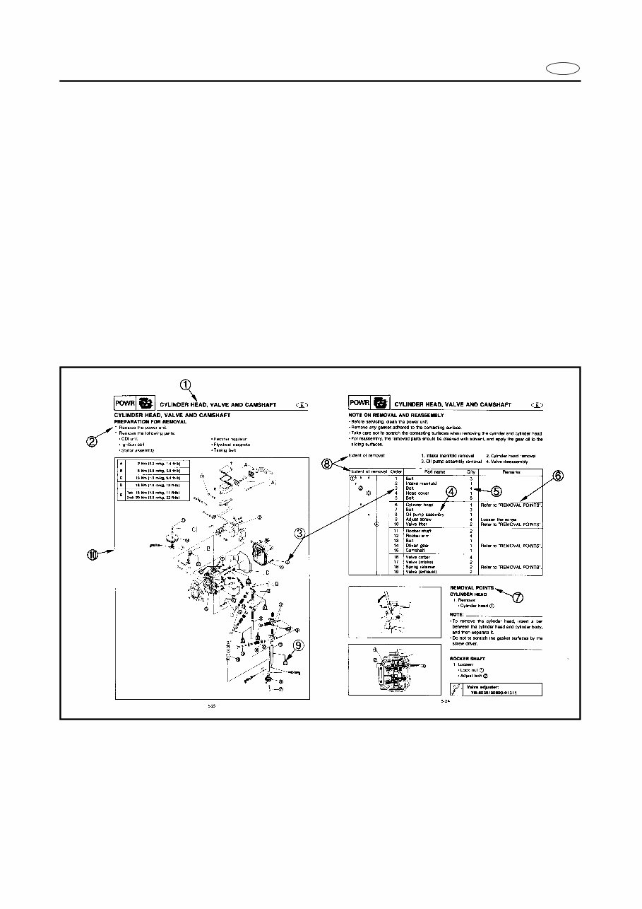
E HOW TO READ DESCRIPTIONS 1. An easy-to-see disassembly illustration is mainly provided for a disassembly job. 2. Numbers are given in the order of a disassembly job in the disassembly illustration. 3. An explanation of jobs and notes is presented in an easy-to-read way by the use of sym- bol marks. The meanings of the symbol marks are given on the next page. 4. A job instruction chart accompanies the assembly illustration, providing the order of jobs, names of parts, notes in jobs, etc. 5. In addition to the disassembly illustration, “REMOVAL POINTS” is provided to supple- ment in detail the explanation which does or cannot necessarily cover the main jobs. 6. Jobs necessary before and after those which are not included in the disassembly illustra- tion are explained before the same illustration as related jobs. 1 Section 2 Preparation for removal 3 Order of removal 4 Part name 5 Q’ty 6 Remarks 7 Removal points 8 Extent of removal 9 Symbol mark 0 Exploded diagram
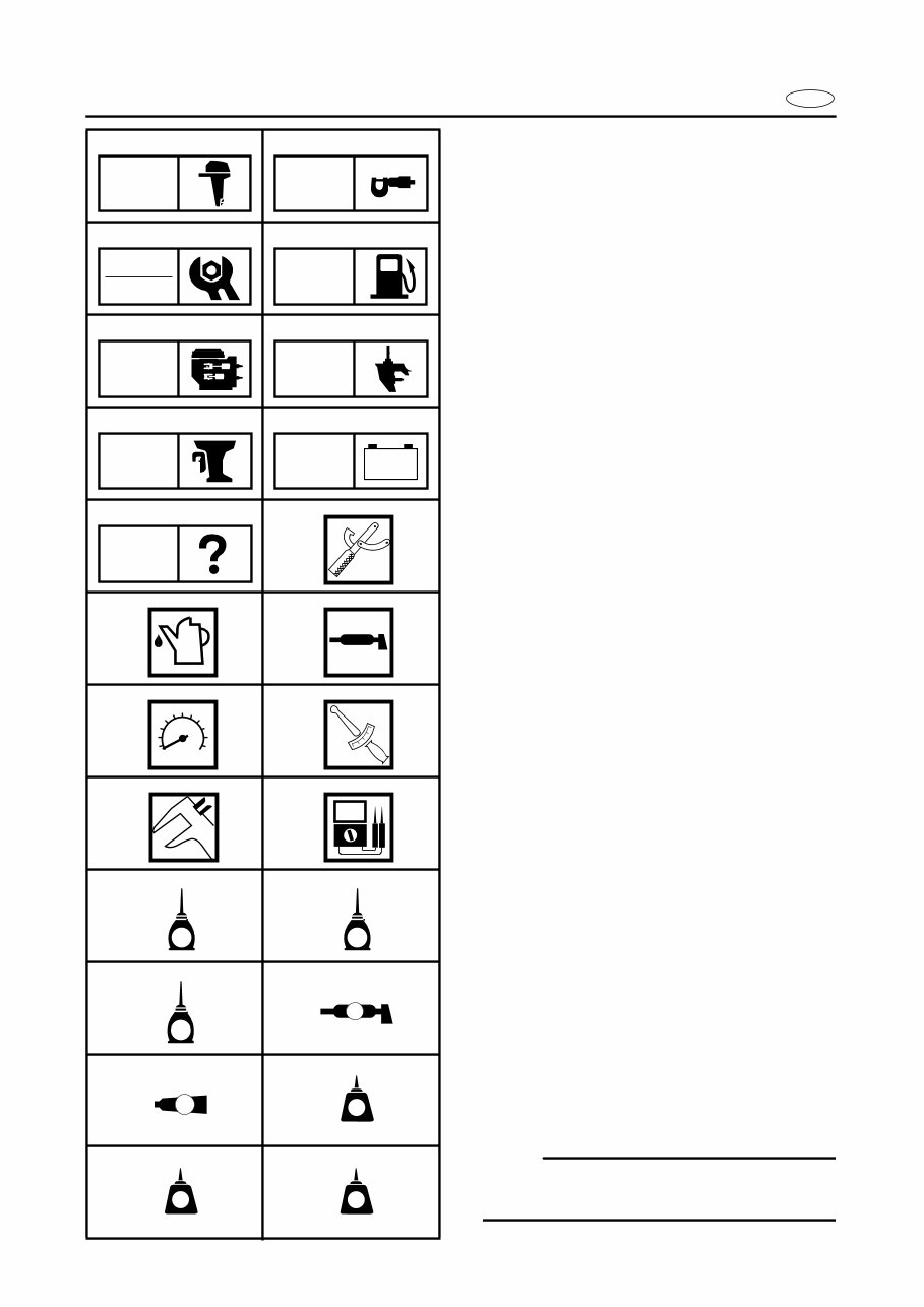
E A50001-1-4 SYMBOLS Symbols 1 to 9 are designed as thumb- tabs to indicate the content of a chapter. 1 General Information 2 Specifications 3 Periodic Inspection and Adjustment 4 Fuel System 5 Power Unit 6 Lower Unit 7 Bracket Unit 8 Electrical System 9 Trouble analysis Symbols 0 to F indicate specific data: 0 Special Tool A Specified liquid B Specified grease C Specified engine speed D Specified torque E Specified measurement F Specified electrical value [Resistance (Ω), Voltage (V), Electric current (A)] Symbol G to J in an exploded diagram indicate grade of lubricant and location of lubrication point: G Apply Yamaha engine oil H Apply Yamaha gear-case lubricant I Apply molybdenum disulfide oil J Apply water resistant grease (Yamaha marine grease A, Yamaha marine grease) Symbols K to N in an exploded diagram indicate grade of sealing or locking agent, and location of application point: K Apply Gasket Maker L Apply LOCTITE No. 271 (Red LOCTITE) M Apply LOCTITE No. 242 (Blue LOCTITE) N Apply LOCTITE No. 572 NOTE: In this manual, the above symbols may not be used in every case. 1 2 3 4 5 6 7 8 9 0 A B C D E F G H I J K L M N GEN INFO SPEC INSP ADJ FUEL POWR LOWR BRKT – + ELEC TRBL ANLS T R . . E G M A GM 271 LT 242 LT 572 LT
E INDEX GENERAL INFORMATION 1 SPECIFICATIONS 2 SPEC PERIODIC INSPECTION AND ADJUSTMENT 3 FUEL SYSTEM 4 FUEL POWER UNIT 5 POWR LOWER UNIT 6 LOWR BRACKET UNIT 7 BRKT ELECTRICAL SYSTEM 8 ELEC TROUBLE ANALYSIS 9 GEN INFO INSP ADJ – + TRBL ANLS A30000-0
E 1 2 3 4 5 6 7 8 9 GEN INFO CHAPTER 1 GENERAL INFORMATION IDENTIFICATION............................................................................................. 1-1 SERIAL NUMBER ..................................................................................... 1-1 STARTING SERIAL NUMBERS ............................................................... 1-1 SAFETY WHILE WORKING ............................................................................ 1-2 FORE PREVENTION ................................................................................. 1-2 VENTILATION........................................................................................... 1-2 SELF-PROTECTION .................................................................................. 1-2 OILS, GREASES AND SEALING FLUIDS ................................................ 1-2 GOOD WORKING PRACTICES ................................................................ 1-3 DISASSEMBLY AND ASSEMBLY ........................................................... 1-4 SPECIAL TOOLS ............................................................................................. 1-5 MEASURING ............................................................................................ 1-5 REMOVAL AND INSTALLATION ............................................................ 1-6
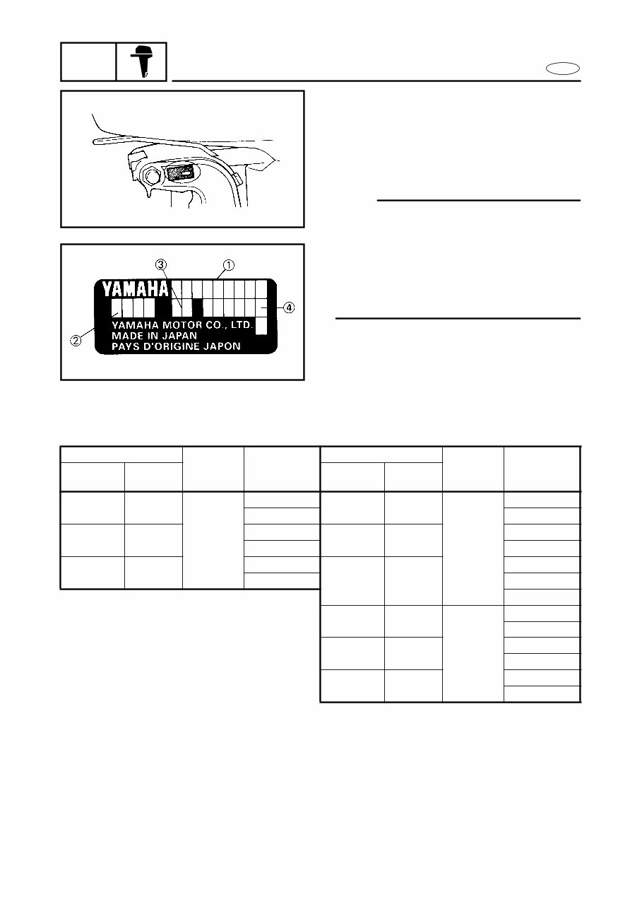
1-1 GEN INFO E IDENTIFICATION A60000-1* IDENTIFICATION SERIAL NUMBER The serial number of the outboard motor is stamped on a plate attached to the port side of the clamp bracket. NOTE: For USA model: As an anti-theft measure, a special label on which the outboard motor serial number is stamped is bonded to the portside of the clamp bracket. The label is specially treated so that peeling it off causes cranks across the serial number 1 Model name 2 Approved model No. 3 Transom height 4 Serial number STARTING SERIAL NUMBERS The starting serial number blocks are as follows: Model Approved model No. Serial Number Model Approved model No. Serial Number Worldwide USA, CANADA Worldwide USA, CANADA F8BMH — 6J7 S: 000490 ~ FT9.9AMH T9.9MH 6G8 L: 304623 ~ L: 301713 ~ X: 703474 ~ F8BEH — S: 200158 ~ FT9.9AEH T9.9EH L: 472276 ~ L: 500786 ~ X: 788442 ~ F8BE — S: 100302 ~ FT9.9AE T9.9ER S: 101224 ~ L: 400964 ~ L: 413584 ~ X: 762552 ~ F9.9BMH F9.9MH 6G9 S: 010452 ~ L: 308168 ~ F9.9BEH F9.9EH S: 200421 ~ L: 500514 ~ F9.9BE — S: 101488 ~ L: 402044 ~
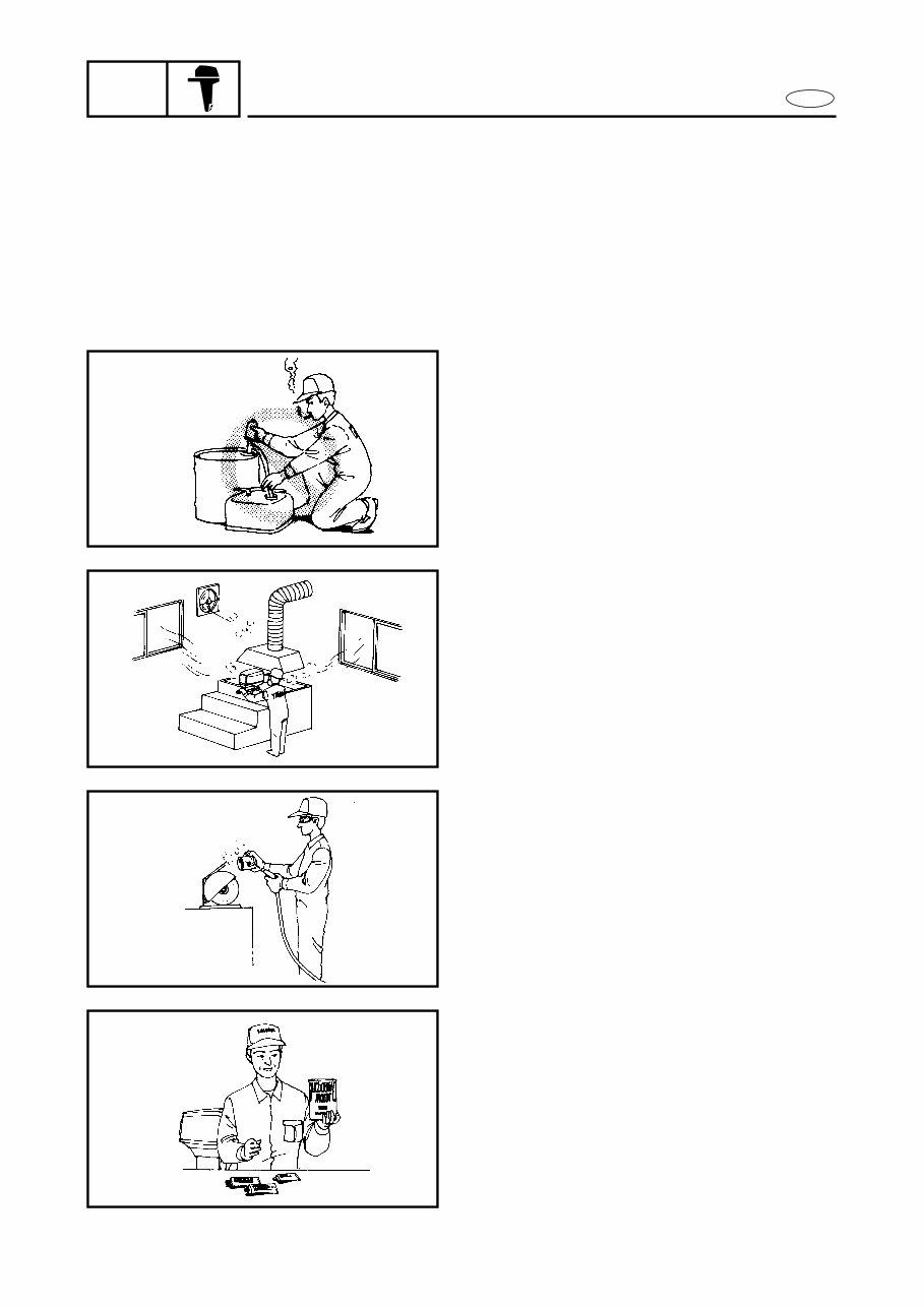
1-2 GEN INFO E SAFETY WHILE WORKING SAFETY WHILE WORKING The procedures given in this manual are those recommended by Yamaha to be fol- lowed by Yamaha dealers and their mechanics. FIRE PREVENTION Gasoline (petrol) is highly flammable. Petroleum vapor is explosive if ignited. Do not smoke while handling gasoline (petrol), and keep it away from heat, sparks, and open flames. VENTILATION Petroleum vapor is heavier than air and if inhaled in large quantities will not support life. Engine exhaust gases are harmful to breathe. When test-running an engine indoors, maintain good ventilation. SELF-PROTECTION Protect your eyes with suitable safety spec- tacles or safety goggles when using com- pressed air, when grinding or when doing any operation which may cause particles to fly off. Protect hands and feet by wearing safety gloves or protective shoes appropriate to the work you are doing. OILS, GREASES AND SEALING FLUIDS Use only genuine Yamaha oils, grease and sealing fluids or those recommended by Yamaha.
This manual covers all versions of the following machines:
2015 Yamaha F8B 4-Stroke Outboards
2015 Yamaha F9.9B 4-Stroke Outboards
2015 Yamaha T9.9B 4-Stroke Outboards
After payment, our informative repair manual, owners manuals, and parts catalogs contain all the information you'll need to perform repairs, look up parts, or do routine maintenance on your machine. You will have access to information regarding the following topics:
General Information
Routine Maintenance
Engine Removal and Installation
Fuel System
Lubrication and Cooling System
Engine Specifications
Transmission, Drive Chain & Sprockets
Steering System
Shocks
Body Work
Intake & Exhaust
Electrical System
Advanced Troubleshooting
With our repair manuals, find the page pertaining to your job, print it off, and get working on your machine. No more ruining your expensive paper shop manual with grease and dirt.
Broke down on the trail or site and have a smartphone? What a cool way to find your problem and repair it on the trail, no downtime on the job site. With our repair manuals, you instantly have access to the material needed to get you running again. Kind of tough to do that with a paper manual.
And did we mention the fact that you're saving the trees? All our repair manuals come with a lifetime protection policy. If lost or damaged, simply contact us and we'll replace it free of charge for life.
We provide various repair service manuals, workshop manuals, repair manuals, owners manuals, parts catalogs, and other various manuals, all in an electronic format.
UTVs, motorcycles, ATVs, quads, snowmobiles, Seadoo, equipment, small engines, inboards, outboards, and more.