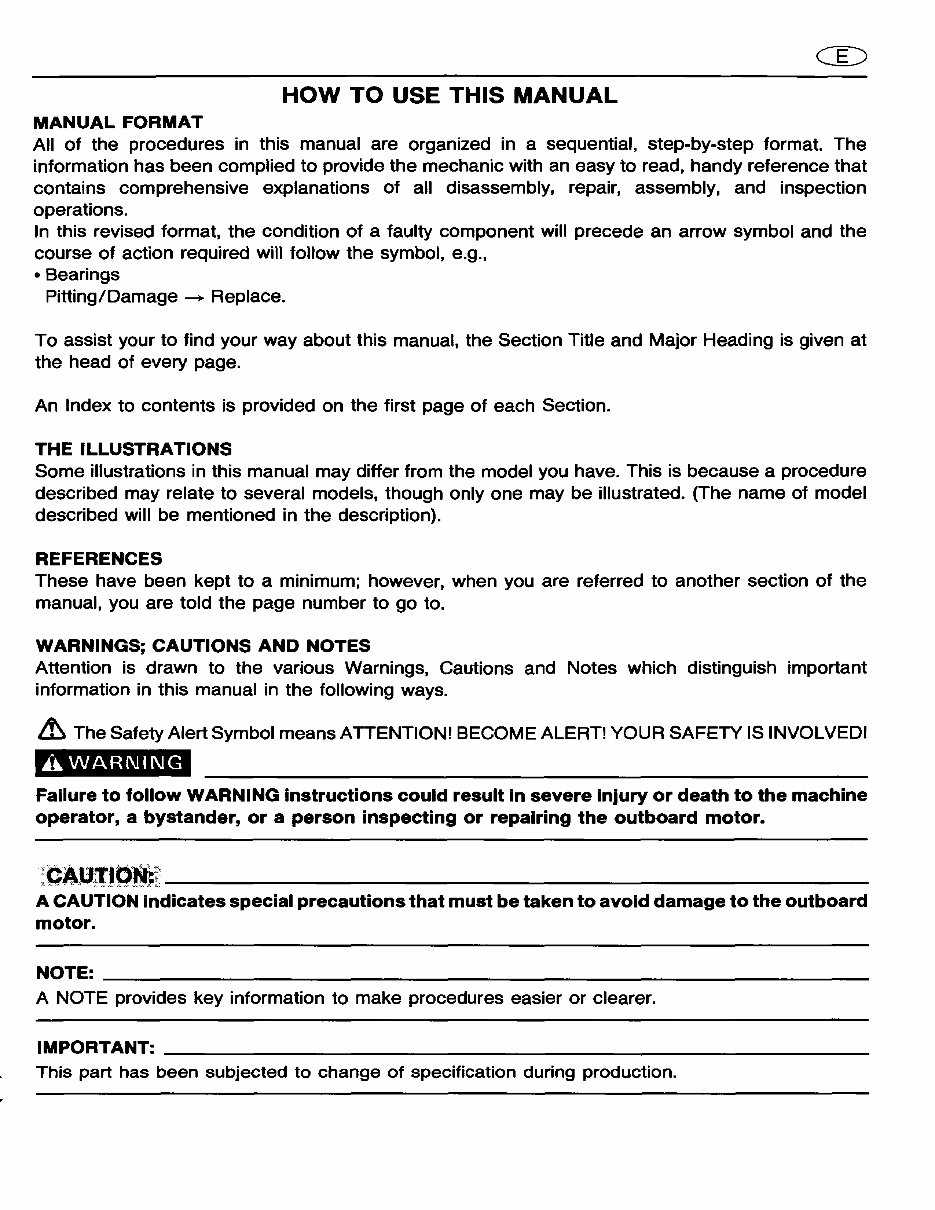
HOW TO USE THIS MANUAL MANUAL FORMAT All of the procedures in this manual are organized in a sequential, step-by-step format. The information has been complied to provide the mechanic with an easy to read, handy reference that contains comprehensive explanations of all disassembly, repair, assembly, and inspection operations. In this revised format, the condition of a faulty component will precede an arrow symbol and the course of action required will follow the symbol, e.g., • Bearings Pitting/Damage ---+ Replace. To assist your to find your way about this manual, the Section Title and Major Heading is given at the head of every page. An Index to contents is provided on the first page of each Section. THE ILLUSTRATIONS Some illustrations in this manual may differ from the model you have. This is because a procedure described may relate to several models, though only one may be illustrated. (The name of model described will be mentioned in the description). REFERENCES These have been kept to a minimum; however, when you are referred to another section of the manual, you are told the page number to go to. WARNINGS; CAUTIONS AND NOTES Attention is drawn to the various Warnings, Cautions and Notes which distinguish important information in this manual in the following ways. ~ The Safety Alert Symbol means ATTENTION! BECOME ALERT! YOUR SAFETY IS INVOLVED! AWARNING Failure to follow WARNING instructions could result in severe injury or death to the machine operator, a bystander, or a person inspecting or repairing the outboard motor. :CAUrcJ~~~---------------------- A CAUTION indicates special precautions that must be taken to avoid damage to the outboard motor. NOTE: ______________________________________________________________ _ A NOTE provides key information to make procedures easier or clearer. IMPORTANT: ________________________________________________________ __ This part has been subjected to change of specification during production.
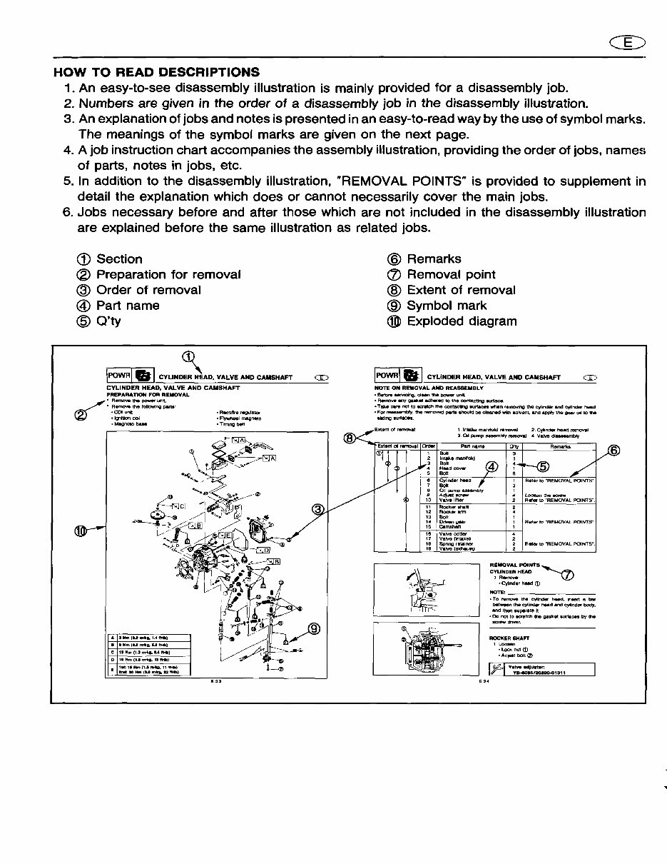
HOW TO READ DESCRIPTIONS 1. An easy-to-see disassembly illustration is mainly provided for a disassembly job. 2. Numbers are given in the order of a disassembly job in the disassembly illustration. 3. An explanation of jobs and notes is presented in an easy-to-read way by the use of symbol marks. The meanings of the symbol marks are given on the next page. 4. A job instruction chart accompanies the assembly illustration, providing the order of jobs, names of parts, notes in jobs, etc. 5. In addition to the disassembly illustration, "REMOVAL POINTS" is provided to supplement in detail the explanation which does or cannot necessarily cover the main jobs. 6. Jobs necessary before and after those which are not included in the disassembly illustration are explained before the same illustration as related jobs. CD Section ® Preparation for removal ® Order of removal ® Part name @ O'ty ~ !POWRlel CYLINDER HEAD, VALVE AND CAMSHAFT CYLINDER HEAD, VALVE AND CAMSHAFT PREPARATION FOR REIIOVAL ~ .. RIItmOY8 the power unit .. A~ the followtng partS, • COl unit • Ignition COl • Magnet:o baM A 2"'" (lUftI'II .. U I'HI) •• NIh(IUnrIIg,U,....' C l' M.., (1-' nrl .. U !'HI) D 1. MIn" ......... ""....) .. A.ctdIra rwgu!alOr .~Imeoneto .. Tirrang belt @ Remarks (!) Removal point ® Extent of removal @ Symbol mark ®l Exploded diagram IPOWRlal CYLINDER HEAD, VALVE AND CAMSHAFT CD NOTE ON REMOVAL AND REASSEMBLY .. Btrtor. .........ana. clean !he power unit .. A-.nowe .,., gukat: adher«l to the contacting surface. .. Take care not 10 .aa~ 1:1'16 corrtBcting .... r1acn whIIn removing the cylinder lind co,tlndar hQ&d .. For reuaemb..,.. !he remCN'9d peru, Ihould be cleaned W'tttI solvent, and apply the gear 011 to !he alldlng .url.ce. . 1. Intake manifold ,.I'JJOY'I!J 2. Cylmdlilr head remoYaI 3. OIl pump assembly rBrnoval .. \Jatve dlaaaembly Put name 11 Rocker .han 12 ROCker arm 13 9011 '4 ~gNr 15 CafNIhlln Ie Val'Ya caner 17 Valva (intake) 18 Spnng retainer 19 V.1Ye (8J!haueu D'I\' A ......... loou.n the KntW Rafe, to 'REMOVAL POINTS·, RlJler to "REMOVAL POINTS·, REMOVAL POINTS~ CYUNDER HEAD 1 RfImOloJe' .. Cytlnder heed CD ~------- .. To rvmCl'Ye the cylinder heIId, Inlier'! a bIu' ~n [he C)'Iindlilr head and <:)'Iind8l'" body, and then IQparale it o Dc not to lIO'etch IIhe gaP&t surf.en by the acrew atYer. ROCKER SHAFT 1 Loo_ o Lock nU1 <D o AdJust bolt 12> I (l4,1 v ..... ., .... r. r YB-aOH/D0a80-01311 6
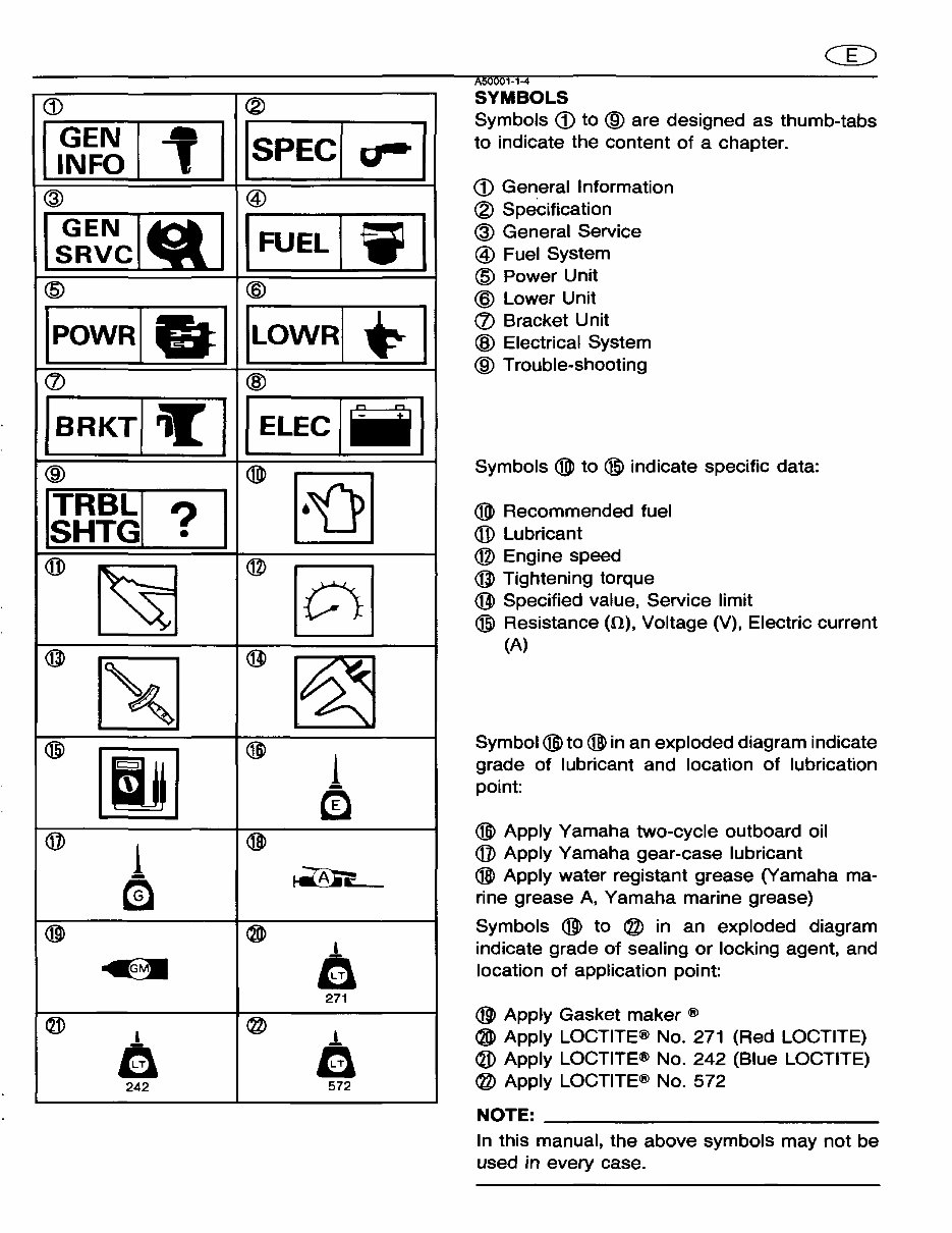
G) 1~~~lll @ 1;:~clQ I @ IPOwRlal (!) jBRKTI ~ I ® IJn'~1 ? I • ® ~ @ ~ @ [I]jJ @ 1 m @ ~ ® • f) 242 ® ISPECi ....... " I @ I FUEL 1.1 @ I LOWRI *'-1 @ I ELEC I ii I ®> ~ @ [Q] @ ~ ®l 1 en @ ~ @ .!. a 271 @ • a 572 A50001-1-4 SYMBOLS Symbols G) to ® are designed as thumb-tabs to indicate the content of a chapter . G) General Information ® Specification @ General Service @ Fuel System @ Power Unit @ Lower Unit (!) Bracket Unit @ Electrical System ® Trouble-shooting Symbols ®> to @ indicate specific data: ®> Recommended fuel ® Lubricant @ Engine speed @ Tightening torque @ Specified value, Service limit @ Resistance (0), Voltage (V), Electric current (A) Symbol ®l to @ in an exploded diagram indicate grade of lubricant and location of lubrication pOint: ®l Apply Yamaha two-cycle outboard oil @ Apply Yamaha gear-case lubricant @ Apply water registant grease (yamaha ma- rine grease A, Yamaha marine grease) Symbols @ to @ in an exploded diagram indicate grade of sealing or locking agent, and location of application point: @ Apply Gasket maker ® ~ Apply LOCTITE® No. 271 (Red LOCTITE) ® Apply LOCTITE® No. 242 (Blue LOCTITE) @ Apply LOCTITE® No. 572 NOTE: __________________________ _ In this manual, the above symbols may not be used in every case.
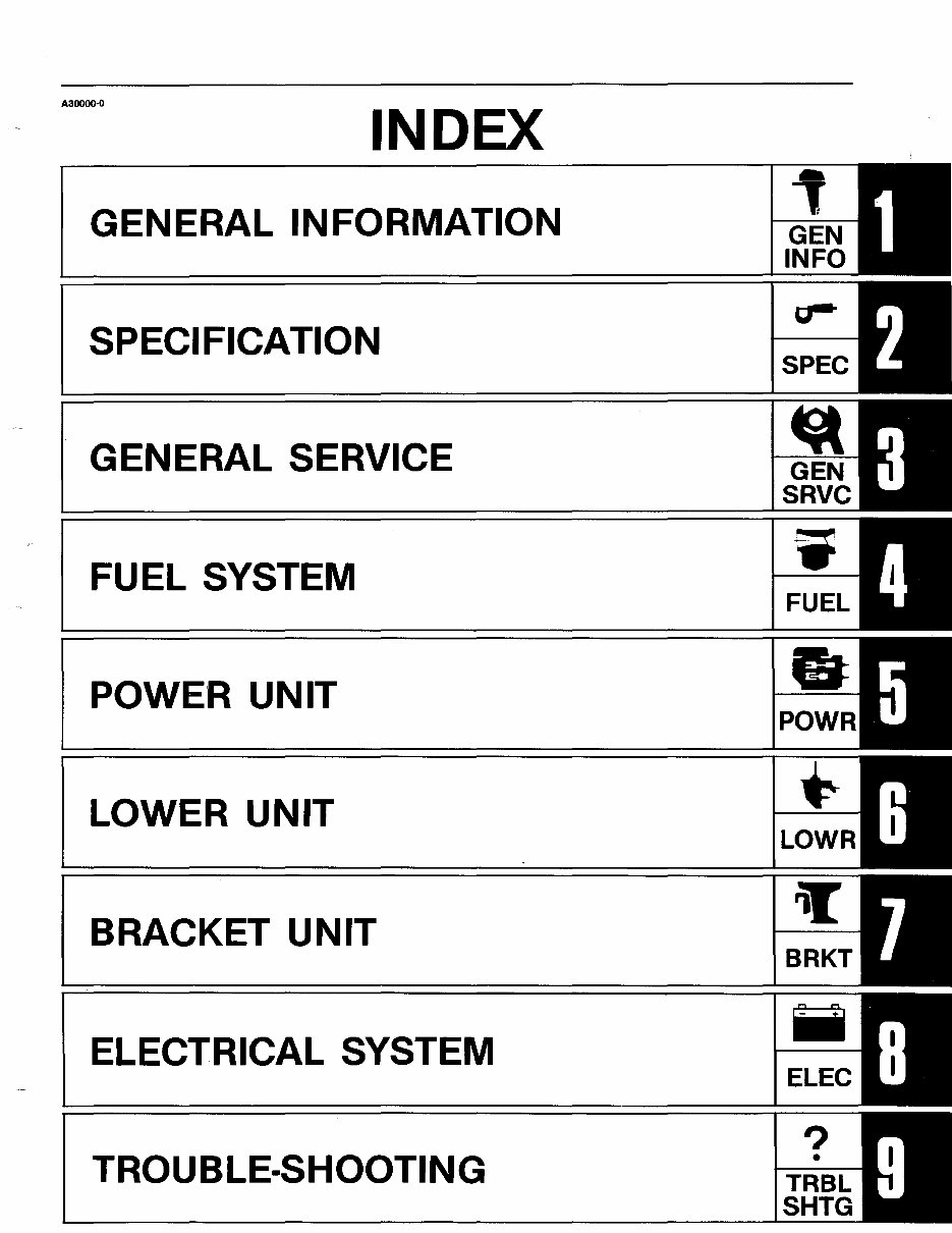
A30000-0 INDEX GENERAL INFORMATION SPECIFICATION GENERAL SERVICE FUEL SYSTEM POWE'R UNIT LOWER UNIT ~ BRACKET UNIT iT ELECTRICAL SYSTEM iii ? TROUBLE·SHOOTING •
1~~111 ___________________ CD_E CHAPTER 1 GENERAL INFORMATION IDENTIFICATION ................................................................................................ 1-1 SERIAL NUMBER .......................................................................................... 1-1 ENGINE SERIAL NUMBER .......................................................................... 1-1 STARTING SERIAL NUMBERS .................................................................. 1-1 SAFETY WHILE WORKING .............................................................................. 1-2 FIRE PREVENTION ...................................................................................... 1-2 VENTILATION ................................................................................................ 1-2 SELF-PROTECTION ...................................................................................... 1-2 OILS, GREASES AND SEALING FLUIDS .................................................. 1-3 GOOD WORKING PRACTICES ................................................................... 1-4 DISASSEMBLY AND ASSEMBLY ............................................................... 1-4 SPECIAL TOOLS ................................................................................................ 1-5 FOR TUNE-UP ............................................................................................... 1-5 FOR POWER UNIT SERVICE ..................................................................... 1-6 FOR LOWER UNIT SERVICE ...................................................................... 1-8
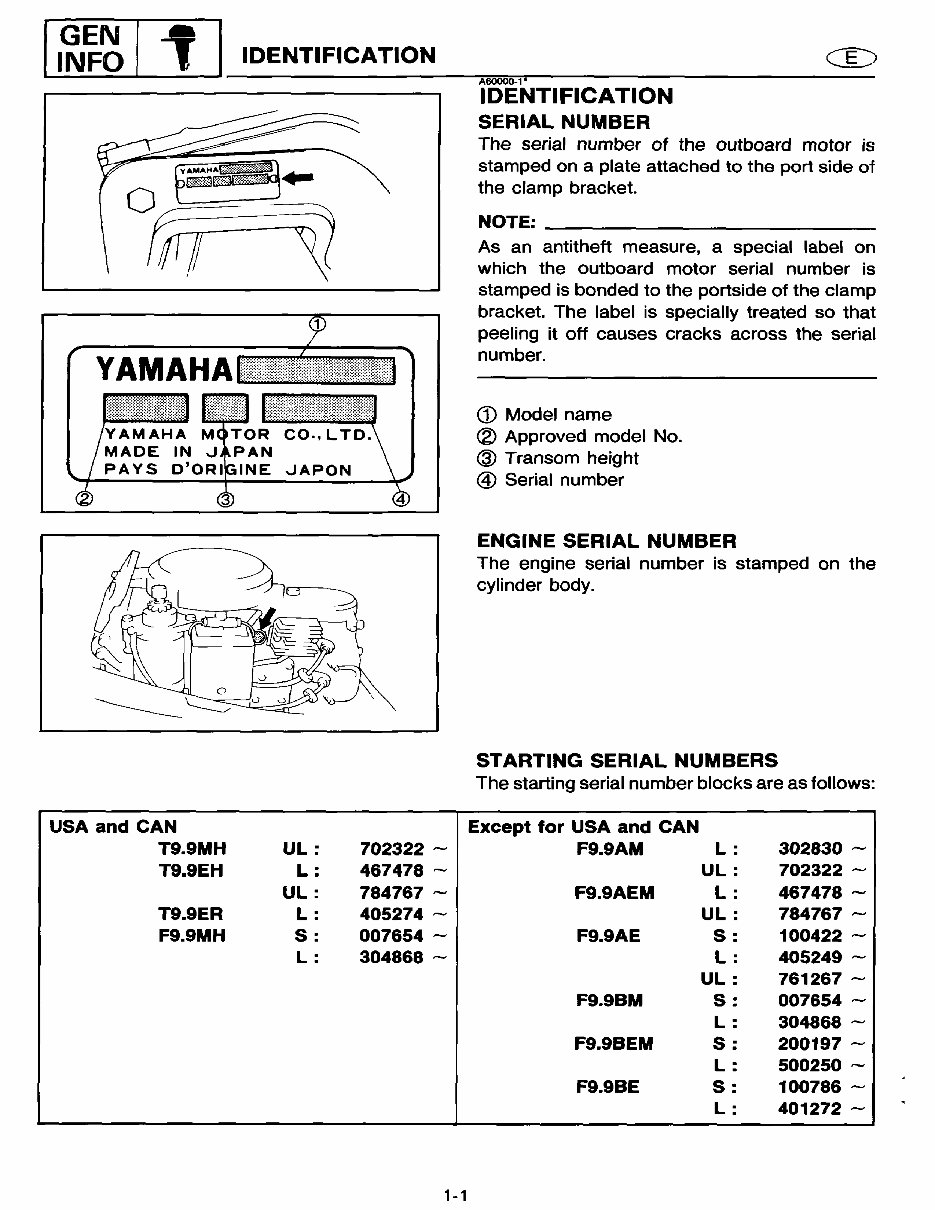
[ I~~~ I 1 I IDENTIFICATION USA and CAN T9.9MH UL: 702322 ~ T9.9EH L: 467478 ~ UL: 784767 ~ T9.9ER L : 405274 - F9.9MH S: 007654 - L: 304868 - 1-1 AeoOOO-1" IDENTIFICATION SERIAL NUMBER The serial number of the outboard motor is stamped on a plate attached to the port side of the clamp bracket. NOTE: __________________________ __ As an antitheft measure, a special label on which the outboard motor serial number is stamped is bonded to the portside of the clamp bracket. The label is specially treated so that peeling it off causes cracks across the serial number. <D Model name ® Approved model No. ® Transom height @ Serial number ENGINE SERIAL NUMBER The engine serial number is stamped on the cylinder body. STARTING SERIAL NUMBERS The starting serial number blocks are as follows: Except for USA and CAN F9.9AM L : 302830 ~ UL: 702322 ~ F9.9AEM L: 467478 ,..., UL: 784767 ,..., F9.9AE S: 100422 ~ L: 405249 ~ UL: 761267 ~ F9.9SM S: 007654 ~ L : 304868 ~ F9.9BEM S: 200197 ~ L : 500250 ~ F9.9SE S: 100786 ~ L: 401272 ~
After payment, MyGreenManuals.com is your number one source for repair manuals. Our informative repair manuals, owner's manuals, and parts catalogs contain all the information you'll need to perform repairs, look up parts, or do routine maintenance on your machine. You will have access to information regarding the following topics:
General Information
Routine Maintenance
Engine Removal and Installation
Fuel System
Lubrication and Cooling System
Engine Specifications
Transmission, Drive Chain & Sprockets
Steering System
Shocks
Body Work
Intake & Exhaust
Electrical System
Advanced Troubleshooting
With our repair manuals, find the page pertaining to your job, print it off, and get working on your machine. No more ruining your expensive paper shop manual with grease and dirt.
Broke down on the trail or site and have a smartphone? With our repair manuals, you instantly have access to the material needed to get you running again. Kind of tough to do that with a paper manual.
And did we mention the fact that you're saving the trees? All our repair manuals come with a lifetime protection policy. If lost or damaged, simply contact us and we'll replace it free of charge for life.
We provide various repair service manuals, workshop manuals, repair manuals, owner's manuals, parts catalogs, and other various manuals, all in an electronic format.
UTVs, motorcycles, ATVs, quads, snowmobiles, Seadoo, equipment, small engines, inboards, outboards, and more.
* Instant access
* No shipping cost
* Get a manual so no waiting, repair it now
If you are looking for a specific manual and cannot find it or do not see it listed, then contact our customer support team via the contact us link above with details of the required manual and we will do our absolute best to find and list it for you.
Instant access after payment. Thank you
Recently Viewed
5,521,897Happy Clients
2,594,462eManuals
1,120,453Trusted Sellers
15Years in Business
Price:
Actual Price:
1995-2008 YAMAHA 9.9 4-STROKE HIGH THRUST OUTBOARD Repair