1992-1995 Yamaha 9.9HP 4-Stroke High Thrust Outboard Repair Manual
What's Included?
Lifetime Access
Fast Download Speeds
Online & Offline Access
Access PDF Contents & Bookmarks
Full Search Facility
Print one or all pages of your manual
Quick Reference Data SPARK PLUG APPLICATION Gap Torque Engine model year Type mm (in) N•m (ft.-lb.) F9.9 (K-Q) 1985-1992 (NGK) CR6HS 0.6-0.7 (0.024-0.028) 12 (9)* F9.9 (R-W) 1993-1998 (NGK) CR6HS 0.6-0.7 (0.024-0.028) 13 (9.4)* F15 (W) 1998 (NGK) DPR6EA-9 0.9 (0.04) 18 (13)* F25 (W) 1998 (NGK) DPR6EA-9 0.9 (0.04) 17.2 (12.6)* F25 (X) 1999 (NGK) DPR6EA-9 0.9-1.0 (0.035-0.039) 17.2 (12.6)* F50 (T-W) 1995-1998 (NGK) DPR6EA-9 0.8-0.9 (0.031-0.035) 17.0 (12.5)* F50 (X) 1999 (NGK) DPR6EA-9 0.9 (0.035) 18.0 (13)* F80 (X) 1999 (NGK) LFR5A-11 1.1 (0.043) 25 (18)* F100 (X) 1999 (NGK) LFR5A-11 1.1 (0.043) 25 (18)* *Finger-tighten the spark plug (s) before reaching torque specification. ENGINE OIL VISCOSITY Engine model Oil type SAE API F9.9 4-Stroke 10W-30, 10W-40 SE, SF, SE-SF, SE-SF-CC F15 4-Stroke 10W-30, 10W-40, 20W-40 SE, SF, SG, SH F25 4-Stroke 10W-30, 10W-40, 20W-40 SE, SF, SG, SH F50 4-Stroke 10W-30, 10W-40, 20W-40 SE, SF, SG, SH F80 4-Stroke 10W-30, 10W-40 SE, SF, SG, SH F100 4-Stroke 10W-30, 10W-40 SE, SF, SG, SH FUEL GRADE SPECIFICATIONS Fuel type Fuel rating Unleaded regular gasoline 86 PON 1 91 RON 2 1. PON: Pump Octane Number 2. RON: Research Octane Number GENERAL TORQUE SPECIFICATIONS* Nut Bolt N•m ft.-lb. 8 mm M5 5.0 3.6 10 mm M6 8.0 5.8 12 mm M8 18 13 14 mm M10 36 25 17 mm M12 43 31 *The torque specified in this chart is for standard fasteners with standard ISO pitch thread. Special components or assemblies that require a special torque are covered in the applicable chapter in this book. IX
RECOMMENDED GEARCASE LUBRICANTS Model Oil type SAE API Capacity T9.9 (MH)(EH)(ER) Hypoid 90 – 320 cm (10.82 oz) F9.9 (MH)(EH) Hypoid 90 – 185 cm (6.25 oz) F15 (MH)(EH) Hypoid 90 – 250 cm (8.45 oz) F25 (MH)(EH)(TH)(ER) (TR) Hypoid 90 – 320 cm (10.8 oz) F40 (TR)(ER)(TH)(EH) Hypoid 90 GL-4 430 cm (14.5 oz) F50 (TR)(ER)(TH)(EH) Hypoid 90 GL-4 430 cm (14.5 oz) T50 (TR) Hypoid 90 GL-4 610 cm (20.6 oz) F80 and F100 Hypoid 90 GL-4 670 cm (22.6 oz) RECOMMENDED ENGINE SPEED Idle speed F9.9 900-1000 rpm T9.9 1100-1200 rpm F15 900-1000 rpm F25 875-975 rpm F40-F50-FT50 700-800 rpm F80-F100 850-950 rpm Full-throttle speed F9.9-T9.9 and F15 4500-5500 rpm F25-F100 5000-6000 rpm Trolling range F9.9 and T9.9 800-900 rpm Maximum horsepower output F9.9 and T9.9 5.9 kW (8 hp) @ 5000 rpm F15 11 kW (15 hp) @ 5000 rpm F25 18.4 kW (25 hp) @ 5500 rpm F40 29.4 kW (40 hp) @ 5500 rpm F50 and T50 36.8 kW (50 hp) @ 5500 rpm F80 58.8 kW (80 hp) @ 5500 rpm F100 73.6 kW (100 hp) @ 5500 rpm MAINTENANCE SCHEDULE 10 hours (break-in) Inspect cowl latches and drain hole(s) Inspect/replace fuel filter Inspect/adjust throttle link rod Inspect/adjust start-in-gear protection Inspect/change engine oil Inspect/adjust valve clearance 1 Inspect engine for water leakage Inspect motor exterior Inspect for exhaust leakage Change lower unit gear oil Inspect battery every month Inspect/clean/change spark plug(s) Check connection of wiring harness 50 hours (3 months) Inspect/replace fuel filter Inspect/change engine oil Replace engine oil filter Inspect/replace timing belt Check engine for exhaust leakage Inspect/clean cooling water passage(s) Inspect propeller for damage Inspect anode(s) for wear Inspect battery Inspect/clean/replace spark plug(s) Inspect and retighten all fasteners X (continued)
MAINTENANCE SCHEDULE (continued) 100 hours (6 months) Inspect fuel line(s) Inspect/replace fuel filter Inspect/adjust start-in-gear protection Inspect/change engine oil Replace engine oil filter Inspect/replace timing belt Inspect/adjust valve clearance 2 Inspect/replace thermostat 3 Inspect engine for exhaust leakage Inspect/clean cooling water passages Change lower unit gear oil Inspect water pump impeller Inspect lower unit for leakage Inspect propeller for damage Inspect anode(s) for wear Inspect battery Inspect/clean/replace spark plug(s) Inspect and retighten all fasteners Inspect and grease all grease points 200 hours (1 year) Inspect cowl latches and drain hole(s) Inspect fuel line Inspect/adjust throttle cable(s) Inspect/adjust idle speed Inspect/adjust shift control cable Inspect spark timing Inspect/replace thermostat 4 Inspect lower unit for leakage Check/reconnect wiring harness 400 hours (2 year) Inspect/adjust valve clearance 5 1. Maintenance not required on F80 and F100 at this interval. 2. Maintenance is required only for F25, F40, F50 and T50 at this interval. 3. Maintenance is required only for F25 at this interval. 4. Maintenance is required only for F40, F50 and T50 at this interval. 5. Maintenance is suggested only for F80 and F100 at this interval. RECOMMENDED ENGINE OIL FOR FOUR-STROKE Model SAE API Capacity F9.9 and T9.9 10W-30, 10W-40 SE, SF, SE-SF-CC 1.0 L (1.06 qt) F15 10W-30, 10W-40 SE, SF, SG or SH 1.0 L (1.06 qt) 1 1.2 L (1.27 qt) 2 F25 10W-30, 10W-40 SE, SF, SG, SH 1.7 L (1.80 qt) 1 1.9 L (2.01 qt) 2 F40 and F50 10W-30, 10W-40 SE, SF, SG, SH 2.0 L (2.11 qt) 1 2.2 L (2.32 qt) 2 T50 10W-30, 10W-40 SE, SF, SG, SH 2.0 L (2.11 qt) 1 2.2 L (2.32 qt) 2 F80 and F100 10W-30, 10W-40 SE, SF, SG, SH 4.5 L (4.75 qt) 1 4.8 L (4.96 qt) 2 1. Quantity without filter. 2. Quantity with filter. XI
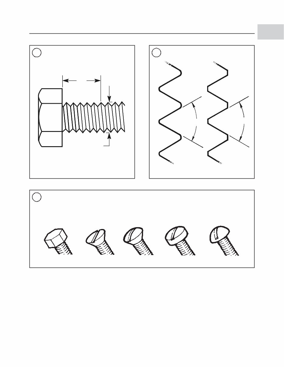
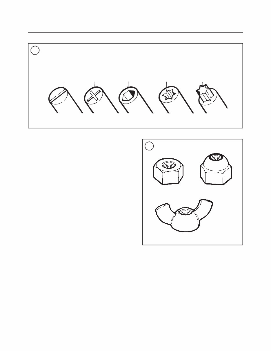
A CAUTION emphasizes areas where equipment damage could cause permanent mechanical damage; however, personal injury is unlikely. A WARNING emphasizes areas where personal in- jury or even death could result from negligence. Me- chanical damage may also occur. WARNINGS must be taken seriously. In some cases, serious injury or death has resulted from disregarding similar warnings. TORQUE SPECIFICATIONS Torque specifications throughout this manual are given in foot-pounds (ft.-lb.), inch-pounds (in.-lb.) and newton meters (N•m.). Newton meters are being adopted in place of meter-kilograms (mkg) in accor- dance with the International Modernized Metric Sys- tem. Existing torque wrenches calibrated in meter-kilograms can be used by performing a simple conversion: move the decimal point one place to the right. For example, 4.7 mkg = 47 N•m. This conversion is accurate enough for most mechanical operations even though the exact mathematical conversion is 3.5 mkg = 34.3 N•m. ENGINE OPERATION All marine engines, whether two or four-stroke, gas- oline or diesel, operate on the Otto cycle of intake, com- pression, power and exhaust phases. Two-Stroke Cycle A two-stroke engine requires one crankshaft revolu- tion (two strokes of the piston) to complete the Otto cy- cle. All engines covered in this manual are a two-stroke design. Figure 1 shows gasoline two-stroke engine op- eration. Four-Stroke Cycle A four-stroke engine requires two crankshaft revolu- tions (four strokes of the piston) to complete the Otto cycle. Figure 2 shows gasoline four-stroke engine op- eration. FASTENERS The material and design of the various fasteners used on marine equipment are carefully thought out and de- signed. Fastener design determines the type of tool re- quired to work with the fastener. Fastener material is carefully selected to decrease the possibility of physical failure or corrosion. See Galvanic Corrosion in this chapter for information on marine materials. Nuts, bolts and screws are manufactured in a wide range of thread patterns. To join a nut and bolt, the di- ameter of the bolt and the diameter of the hole in the nut must be the same. It is just as important that the threads are compatible. The easiest way to determine if fastener threads are compatible is to turn the nut on the bolt, or bolt into its threaded opening, using fingers only. Be sure both pieces are clean. If much force is required, check the thread condition on each fastener. If the thread condi- tion is good but the fasteners jam, the threads are not compatible. Four important specifications describe the thread: 1. Diameter. 2. Threads per inch. 3. Thread pattern. 4. Thread direction Figure 3 shows the first two specifications. Thread pattern is more subtle. Italian and British standards ex- ist, but the most commonly used by marine equipment manufactures are American standard and metric stan- dard. The root and top of the thread are cut differently as shown in Figure 4. Most threads are cut so that the fastener must be turned clockwise to tighten it. These are called right-hand threads. Some fasteners have left-hand threads; they must be turned counterclockwise to tighten. Left-hand threads are used in locations where normal rotation of the equipment would tend to loosen a right-hand threaded fastener. Assume all fasteners use right-hand threads unless the instructions specify oth- erwise. Machine Screws There are many different types of machine screws (Figure 5). Most are designed to protrude above the se- cured surface (rounded head) or be slightly recessed be- low the surface (flat head). In some applications the screw head is recessed well below the fastened surface. Figure 6 shows a number of screw heads requiring dif- ferent types of turning tools. Bolts Commonly called bolts, the technical name for this fastener is cap screw. They are normally described by diameter, threads per inch and length. For example, 2 CHAPTER ONE
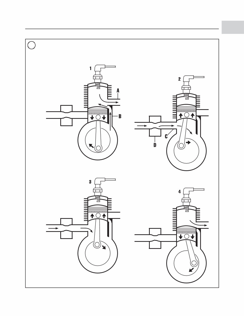
GENERAL INFORMATION 3 1 As the piston travels down- ward, it uncovers the exhaust port (A) allowing the exhaust gases to leave the cylinder. A fresh air-fuel charge, which has been compressed slightly in the crankcase, enters the cylinder through the transfer port (B). Because this charge enters under pressure, it also helps to push out the exhaust gases. As the piston travels down, the exhaust gases leave the cylinder, and the complete cy- cle starts all over again. As the piston almost reaches the top of the travel, the spark plug fires, igniting the com- pressed air-fuel mixture. The piston continues to top dead center (TDC) and is pushed downward by the expanding gases. While the crankshaft contin- ues to rotate, the piston moves upward, covering the transfer (B) and exhaust (A) ports. The piston compresses the new air-fuel mixture and creates a low-pressure area in the crankcase at the same time. As the piston continues to travel, it uncovers the in- take port (C). A fresh air-fuel charge from the carburetor (D) is drawn into the crankcase through the intake port. Spark plug TWO-STROKE OPERATING PRINCIPLES 1
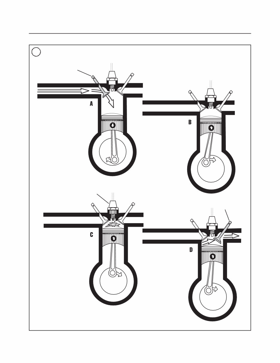
4 CHAPTER ONE 2 FOUR-STROKE GASOLINE OPERATING PRINCIPLES As the piston travels downward, the exhaust valve is closed, and the in- take valve opens, allowing the new air-fuel mixture from the carburetor to be drawn into the cylinder. When the piston reaches the bottom of its travel (BDC), the intake valve closes and remains closed for the next 1 1/2 revolu- tions of the crankshaft. While the crankshaft continues to rotate, the piston moves upward, compressing the air-fuel mixture. As the piston almost reaches the top of its travel, the spark plug fires, igniting the com- pressed air-fuel mixture. The piston continues to top dead center (TDC) and is pushed downward by expanding gases. When the piston al- most reaches BDC, the exhaust valve opens and remains open until the piston is near TDC. The upward travel of the piston forces the exhaust gases out of the cylinder. After the piston has reached TDC, the exhaust valve closes, and the cycle starts all over again. Intake valve Spark plug Exhaust valve
1/4-20 × 1 indicates a bolt 1/4 in. in diameter with 20 threads per inch, 1 in. long. The measurement across two flats of the bolt head indicates the proper wrench size required to turn the bolt. Nuts Nuts are manufactured in a variety of types and sizes. Most are hexagonal (six-sides) and fit on bolts, screws and studs with the same diameter and threads per inch. Figure 7 shows several types of nuts. The common nut is usually used with some type of lockwasher. Self-locking nuts have a nylon insert that helps pre- vent the nut from loosening; no lockwasher is re- quired. Wing nuts are designed for fast removal by hand. Wing nuts are used for convenience in non-critical locations. To indicate the size of a nut, manufactures specify the diameter of the opening and the threads per inch. This is similar to a bolt specification, but without the length di- GENERAL INFORMATION 5 3 1 in. (TPI) Diameter 4 American Metric 60° 60° 5 MACHINE SCREWS Hex Flat Oval Filister Round 1
mension. The measurement across two flats of the nut indicates the wrench size required to turn the nut. Washers There are two basic types of washers: flat washers and lockwashers. A flat washer is a simple disc with a hole that fits the screw or bolt. Lockwashers are de- signed to prevent a fastener from working loose due to vibration, expansion and contraction. Figure 8 shows several types of lockwashers. Note that flat washers are often used between a lockwasher and a fastener to pro- vide a smooth bearing surface. This allows the fastener to be turned easily with a tool. Cotter Pins In certain applications, a fastener must be secured so it cannot possibly loosen. The propeller nut on some marine drive systems is one such application. For this purpose, a cotter pin (Figure 9) and slotted or castel- lated nut is often used. To use a cotter pin, first make sure the pin fits snugly, but not too tight. Then, align a slot in the fastener with the hole in the bolt or axle. In- sert the cotter pin through the nut and bolt or propeller shaft and bend the ends over to secure the cotter pin tightly. If the holes do not align, tighten the nut just enough to obtain the proper alignment. Unless specifi- cally instructed to do so, never loosen the fastener to align the slot and hole. Because the cotter pin is weak- ened after installation and removal, never reuse a cotter pin. Cotter pins are available in several styles, lengths and diameters. Measure cotter pin length from the bottom of its head to the tip of its shortest prong. Snap Rings Snap rings (Figure 10) can be an internal or external design. They are used to retain components on shafts (external type) or inside openings (internal type). Snap rings can be reused if they are not distorted during re- moval. In some applications, snap rings of varying thickness (selective fit) can be selected to position or control end play of parts assemblies. 6 CHAPTER ONE 7 Common nut Self-locking nut Wing nut 6 OPENINGS FOR TURNING TOOLS Slotted Phillips Allen Internal torx External torx
This manual covers all versions of the following machines:
1992 YAMAHA 9.9HP 4-STROKE HIGH THRUST OUTBOARDS
1993 YAMAHA 9.9HP 4-STROKE HIGH THRUST OUTBOARDS
1994 YAMAHA 9.9HP 4-STROKE HIGH THRUST OUTBOARDS
1995 YAMAHA 9.9HP 4-STROKE HIGH THRUST OUTBOARDS
After payment, our informative repair manual, owners manuals, and parts catalogs contain all the information you'll need to perform repairs, look up parts, or do routine maintenance on your machine. You will have access to information regarding the following topics:
General Information
Routine Maintenance
Engine Removal and Installation
Fuel System
Lubrication and Cooling System
Engine Specifications
Transmission, Drive Chain & Sprockets
Steering System
Shocks
Body Work
Intake & Exhaust
Electrical System
Advanced Troubleshooting
With our repair manuals, find the page pertaining to your job, print it off, and get working on your machine. No more ruining your expensive paper shop manual with grease and dirt.
Broke down on the trail or site and have a smartphone? What a cool way to find your problem and repair it on the trail, no downtime on the job site. With our repair manuals, you instantly have access to the material needed to get you running again. Kind of tough to do that with a paper manual.
And did we mention the fact that you're saving the trees? All our repair manuals come with a lifetime protection policy. If lost or damaged, simply contact us and we'll replace it free of charge for life.
We provide various repair service manuals, workshop manuals, repair manuals, owners manuals, parts catalogs, and other various files, all in an electronic format.
UTVs, motorcycles, ATVs, quads, snowmobiles, Seadoo, equipment, small engines, inboards, outboards, and more.
Instant Access after Payment
No Shipping Cost with Download
Get a Download so no waiting, repair it now
Instant Access after Payment. Thank you.
Recently Viewed
5,521,897Happy Clients
2,594,462eManuals
1,120,453Trusted Sellers
15Years in Business
Price:
Actual Price:
1992-1995 Yamaha 9.9HP 4-Stroke High Thrust Outboard Repair Manual