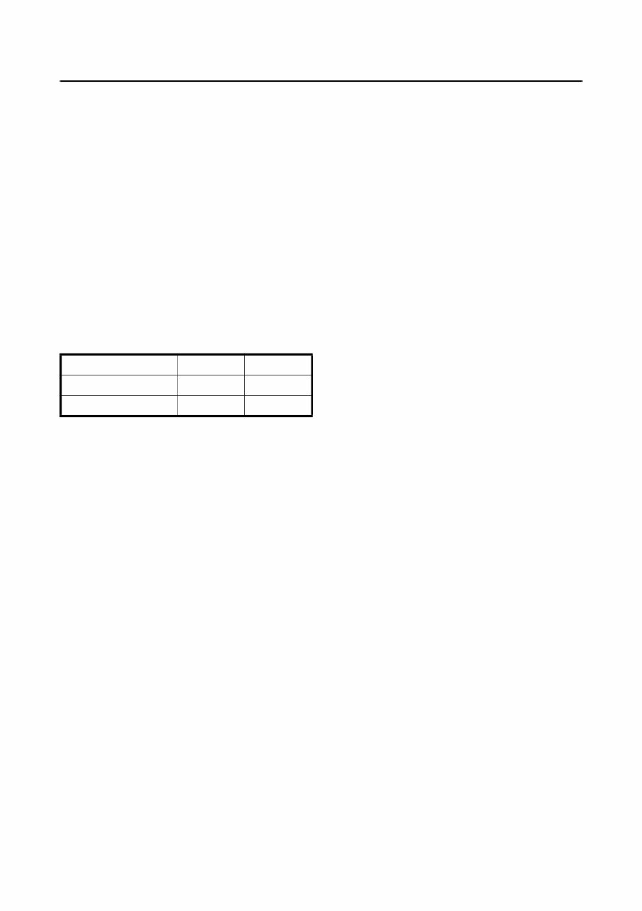
HOW TO USE THIS MANUAL MANUAL FORMAT All of the procedures in this manual are organised in a sequential, step-by-step format. The information has been compiled to provide the mechanic with an easy to read, handly reference that contains comprehensive explanations of all disassembly, repair, assembly, and inspection operations. In this revised format, the condition of a faulty component will precede an arrow symbol and the course of action required will follow the symbol, e.g., •Bearings Pitting/scratches ➔ Replace. To assist you in finding your way through this manual, the section title and major heading is given at the top of every page. MODEL INDICATION Multiple models are referred to in this manual and their model indications are noted as follows. ILLUSTRATIONS The illustrations within this service manual represent all of the designated models. CROSS REFERENCES The cross references have been kept to a minimum. Cross references will direct you to the appropriate section or chapter. Model name (W/W) F6AMH F8CMH USA and Canada name F6MH F8MH Indication F6AMH F8CMH
IMPORTANT INFORMATION In this Service Manual particularly important information is distinguished in the following ways. The safety Alert Symbol means ATTENTION! BECOME ALERT! YOUR SAFETY IS INVOLVED! WARNING Failure to follow WARNING instructions could result in severe injury or death to the machine operator, a bystander or a person inspecting or repairing the outboard motor. CAUTION A CAUTION indicates special precautions that must be taken to avoid damage to the outboard motor. NOTE: A NOTE provides key information to make procedures easier or clearer.
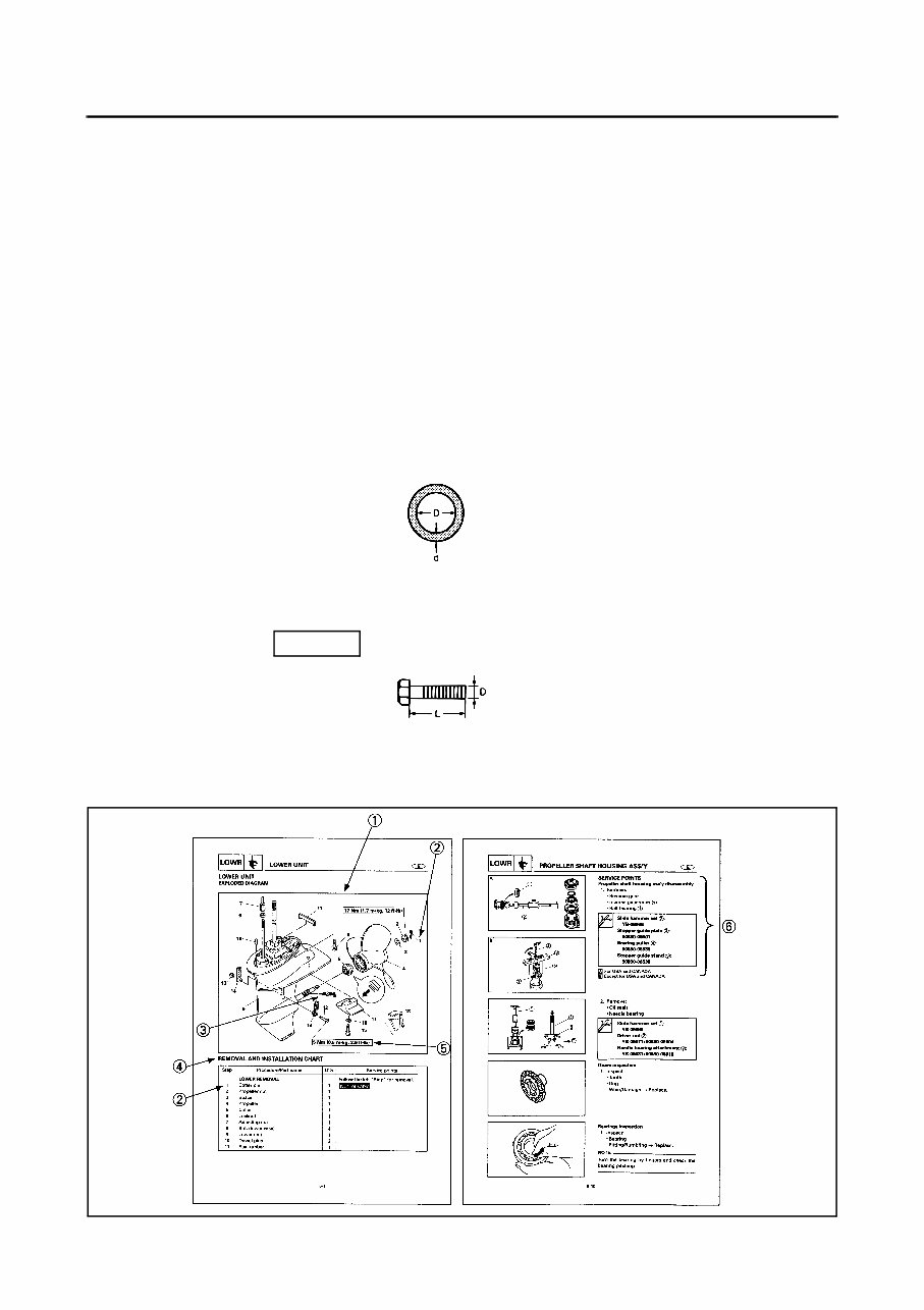
HOW TO USE THIS MANUAL 1 The main points regarding removing/installing and disassembly/assembly procedure are shown in the exploded views. 2 The numbers in the exploded views indicate the required sequence of the procedure and should be observed accordingly. 3 Symbols are used in the exploded views to indicate important aspects of the procedure. A list of meanings for these symbols is provided on the following page. 4 It is important to refer to the job instruction charts at the same time as the exploded views. These charts list the sequence that the procedures should be carried out in, as well as providing exploded on part names, quantities, dimensions and important points relating to each relevant task. Example: O-ring 39.5 x 2.5 mm: inside diameter (D) x ring diameter (d) 5 In addition to tightening torques, the dimensions of the bolts and screws are also mentioned. Example: Bolt and screw size : bolt and screw diameter (D) x length (L) 6 In addition to the exploded views and job instruction charts, this manual provides individual illustrations when further explanations are required to explain the relevant procedure. 10 x 25 mm
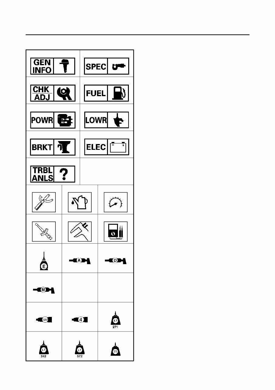
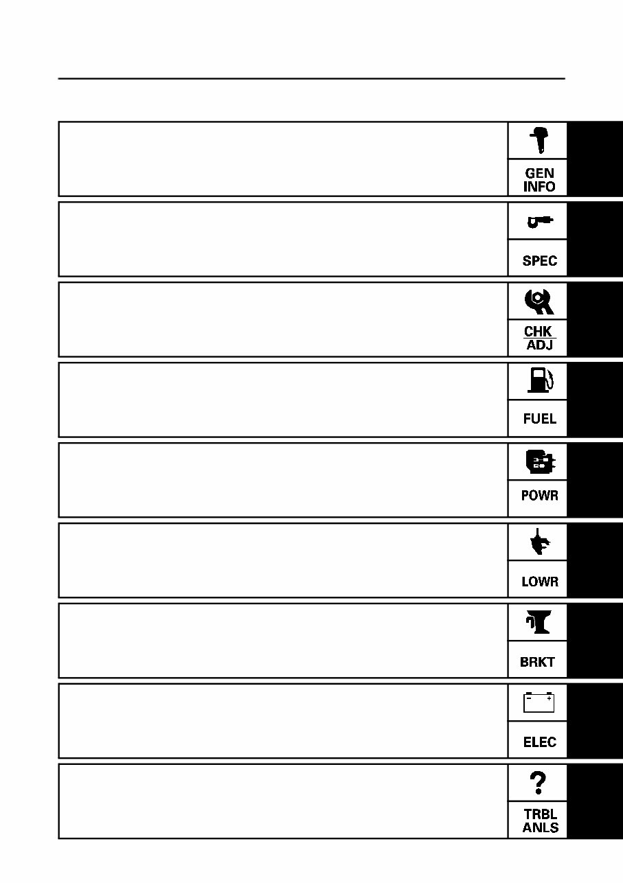
SYMBOLS Symbols 1 to 9 are designed as thumb-tabs to indicate the content of a chapter. 1 General information 2 Specifications 3 Periodic check and adjustment 4 Fuel system 5 Power unit 6 Lower unit 7 Bracket unit 8 Electrical system 9 Trouble analysis Symbols : to E indicate specific data. > Special tool A Specified liquid B Specified engine speed C Specified torque D Specified measurement E Specified electrical value [Resistance (Ω), Voltage (V), Electrical current (A)] Symbols F to I in an exploded diagram indicate the grade of lubricant and the location of the lubricant point. F Apply Yamaha 4-stroke motor oil G Apply water resistant grease (Yamaha grease A, Yamaha marine grease) H Apply Yamaha grease D I Apply molybdenum disufied oil Symbols J to O in an exploded diagram indicate the grade of the sealing or locking agent and the location of the application point. J Apply Gasket Maker ® K Apply Yamabond #4 (Yamaha bond number 4) L Apply LOCTITE ® No.271 (Red LOCTITE) M Apply LOCTITE ® No.242 (Red LOCTITE) N Apply LOCTITE ® No.572 O Apply silicon sealant 1 2 3 4 5 6 7 8 9 0 A B C D E F G H I J K L M N O
1 2 3 4 5 6 7 8 9 CONTENTS GENERAL INFORMATION SPECIFICATIONS PERIODIC CHECK AND ADJUSTMENT FUEL SYSTEM POWER UNIT LOWER UNIT BRACKET UNIT ELECTRICAL SYSTEM TROUBLE ANALYSIS
CHAPTER 1 GENERAL INFORMATION IDENTIFICATION............................................................................................... 1-1 SERIAL NUMBER ....................................................................................... 1-1 STARTING SERIAL NUMBERS ................................................................. 1-1 SAFETY WHILE WORKING .............................................................................. 1-2 FIRE PREVENTION ..................................................................................... 1-2 VENTILATION............................................................................................. 1-2 SELF-PROTECTION .................................................................................... 1-2 OILS, GREASES AND SEALING FLUIDS .................................................. 1-2 GOOD WORKING PRACTICES .................................................................. 1-3 DISASSEMBLY AND ASSEMBLY ............................................................. 1-4 SPECIAL TOOLS ............................................................................................... 1-5 MEASURING .............................................................................................. 1-5 REMOVING AND INSTALLING ................................................................. 1-7 1
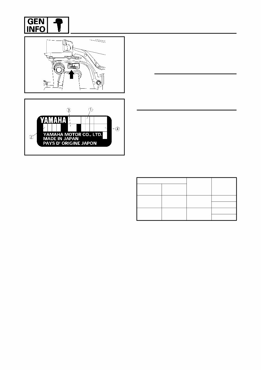
1-1 IDENTIFICATION IDENTIFICATION SERIAL NUMBER The outboard motor’s serial number is stamped on a label which is attached to the port clamp bracket. NOTE: As an antitheft measure, a special label on which the outboard motor’s serial number is stamped is bonded to the port clamp bracket. The label is specially treated so that peeling it off causes cracks across the serial number. STARTING SERIAL NUMBERS The starting serial number blocks are as follows: 1 Model name 2 Approval model code 3 Transom height 4 Serial number Model name Applicable model code Starting serial number World wide USA, Canada F6AMH F6MH 68R S:000101- L:300101- F8CMH F8MH 68T S:000101- L:300101-
You're Reading a Preview
What's Included?
Lifetime Access
Fast Download Speeds
Online & Offline Access
Access PDF Contents & Bookmarks
Full Search Facility
Print one or all pages of your manual
$31.99
2001 2002 2003 2004 2005 2006 2007 2008 2009 2010 2011 Yamaha 8hp 4-stroke High Thrust Outboard models Service Manual
Discover the comprehensive Yamaha Service Manual for 2001-2011 8hp 4-stroke High Thrust models, manual number LIT-18616-T8-00. This manual is a valuable resource for both professional mechanics and DIY enthusiasts, providing in-depth coverage of repair topics including General Information, Periodic Inspection and Adjustments, Fuel System, Power Unit, Lower Unit, Electrical System, Bracket Unit, Specification, Troubleshooting, and many subsections within each section. Additionally, it includes detailed Wiring and Circuit Diagrams, illustrations, photos, exploded views, step-by-step Instructions, Diagnostics, and more.
With the convenience of printable pages, this manual eliminates the need to wait for shipping, saving on postage and packaging costs. It's an essential tool for DIY mechanics looking to save on dealer labor expenses, offering guidance on maintenance tasks that are often simpler than expected. The manual is available in a file format compatible with all versions of Windows and Mac, and it is presented in English, requiring Adobe Reader for access.
Reviews
Q&A
Recently Viewed
5,521,897Happy Clients
2,594,462eManuals
1,120,453Trusted Sellers
15Years in Business
Price:
Actual Price:
2001 2002 2003 2004 2005 2006 2007 2008 2009 2010 2011 Yamaha 8hp 4-stroke High Thrust Outboard models Service Manual







 Lifetime Access




