6C12G11 GEN INFO 1 2 3 4 5 6 7 8 9 General information How to use this manual ................................................................................. 1-1 Manual format............................................................................................ 1-1 Symbols ..................................................................................................... 1-2 Safety while working...................................................................................... 1-3 Fire prevention........................................................................................... 1-3 Ventilation .................................................................................................. 1-3 Self-protection ........................................................................................... 1-3 Parts, lubricants, and sealants .................................................................. 1-3 Good working practices ............................................................................. 1-4 Disassembly and assembly ....................................................................... 1-4 Identification ................................................................................................... 1-4 Applicable models ..................................................................................... 1-4 Serial number ............................................................................................ 1-5 Outline of features ......................................................................................... 1-6 Features and benefits .................................................................................... 1-7 Fuel system ............................................................................................... 1-7 Solenoid valve ........................................................................................... 1-8 Electronic control system........................................................................... 1-9 ECM (Electric Control Module) ................................................................ 1-10 Variable trolling RPM switch (optional) .................................................... 1-11 Propeller selection ....................................................................................... 1-12 Propeller size ........................................................................................... 1-12 Selection .................................................................................................. 1-12 Predelivery checks ...................................................................................... 1-13 Checking the fuel system ........................................................................ 1-13 Checking the engine oil level ................................................................... 1-13 Checking the gear oil level ...................................................................... 1-13 Checking the battery................................................................................ 1-13 Checking the outboard motor mounting height ........................................ 1-14 Checking the remote control cables ........................................................ 1-14 Checking the steering system ................................................................. 1-15 Checking the gear shift and throttle operation ......................................... 1-15 Checking the power trim and tilt system .................................................. 1-15 Checking the engine start switch and engine stop lanyard switch .......... 1-15 Checking the cooling water pilot hole ...................................................... 1-16 Test run ................................................................................................... 1-16 Break-in ................................................................................................... 1-17 After test run ............................................................................................ 1-17
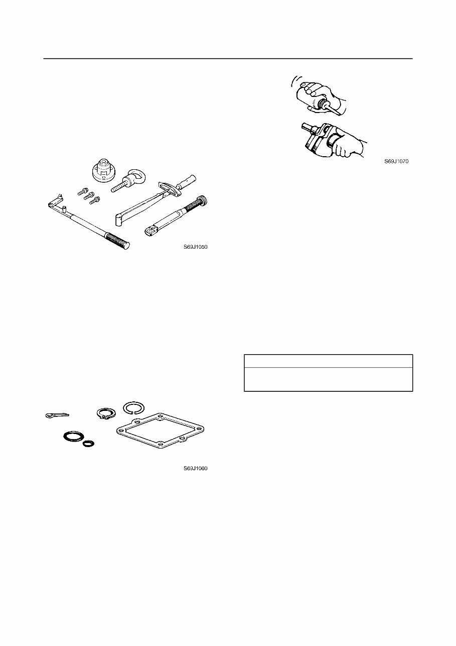
GEN INFO General information 1-1 6C12G11 How to use this manual 1 Manual format The format of this manual has been designed to make service procedures clear and easy to under- stand. Use the information below as a guide for effective and quality service. 1 Parts are shown and detailed in an exploded diagram and are listed in the components list. 2 Tightening torque specifications are provided in the exploded diagrams and after a numbered step with tightening instructions. 3 Symbols are used to indicate important aspects of a procedure, such as the grade of lubricant and lubrication point. 4 The components list consists of part names and part quantities, as well as bolt and screw dimen- sions. 5 Service points regarding removal, checking, and installation are shown in individual illustrations to explain the relevant procedure. NOTE: For troubleshooting procedures, see Chapter 9, “Troubleshooting.” LOWR Lower unit 6-5 62Y5A11 Lower unit No. Part name Q’ty Remarks 1 Lower unit 1 2 Plastic tie 1 Not reusable 3 Hose 1 4 Check screw 1 5 Gasket 2 Not reusable 6 Dowel pin 2 7 Bolt 4 M10 40 mm 8 Drain screw 1 9 Grommet 1 10 Bolt 1 M 10 45 mm 11 Bolt 1 M8 60 mm 12 Thrust washer 1 13 Propeller 1 14 Washer 1 15 Washer 1 16 Cotter pin 1 Not reusable 17 Propeller nut 1 18 Trim tab 1 LOWR Lower unit 6-19 62Y5A11 Removing the drive shaft 1. Remove the drive shaft assembly and pinion, and then pull out the forward gear. Disassembling the drive shaft 1. Install the pinion nut 1, tighten it finger tight, and then remove the drive shaft bearing 2 using a press. CAUTION: • Do not press the drive shaft threads a directly. • Do not reuse the bearing, always replace it with a new one. Disassembling the forward gear 1. Remove the taper roller bearing from the forward gear using a press. CAUTION: Do not reuse the bearing, always replace it with a new one. 2. Remove the needle bearing from the for- ward gear. CAUTION: Do not reuse the bearing, always replace it with a new one. Drive shaft holder 4 1: 90890-06518 Pinion nut holder 2: 90890-06505 Socket adapter 2 3: 90890-06507 Bearing inner race attachment 3: 90890-06639 S62Y6850K Bearing separator 1: 90890-06534 Stopper guide plate 2: 90890-06501 Stopper guide stand 3: 90890-06538 Bearing puller 4: 90890-06535 Bearing puller claw 1 5: 90890-06536 S62Y6740K 5 4 3 2 1
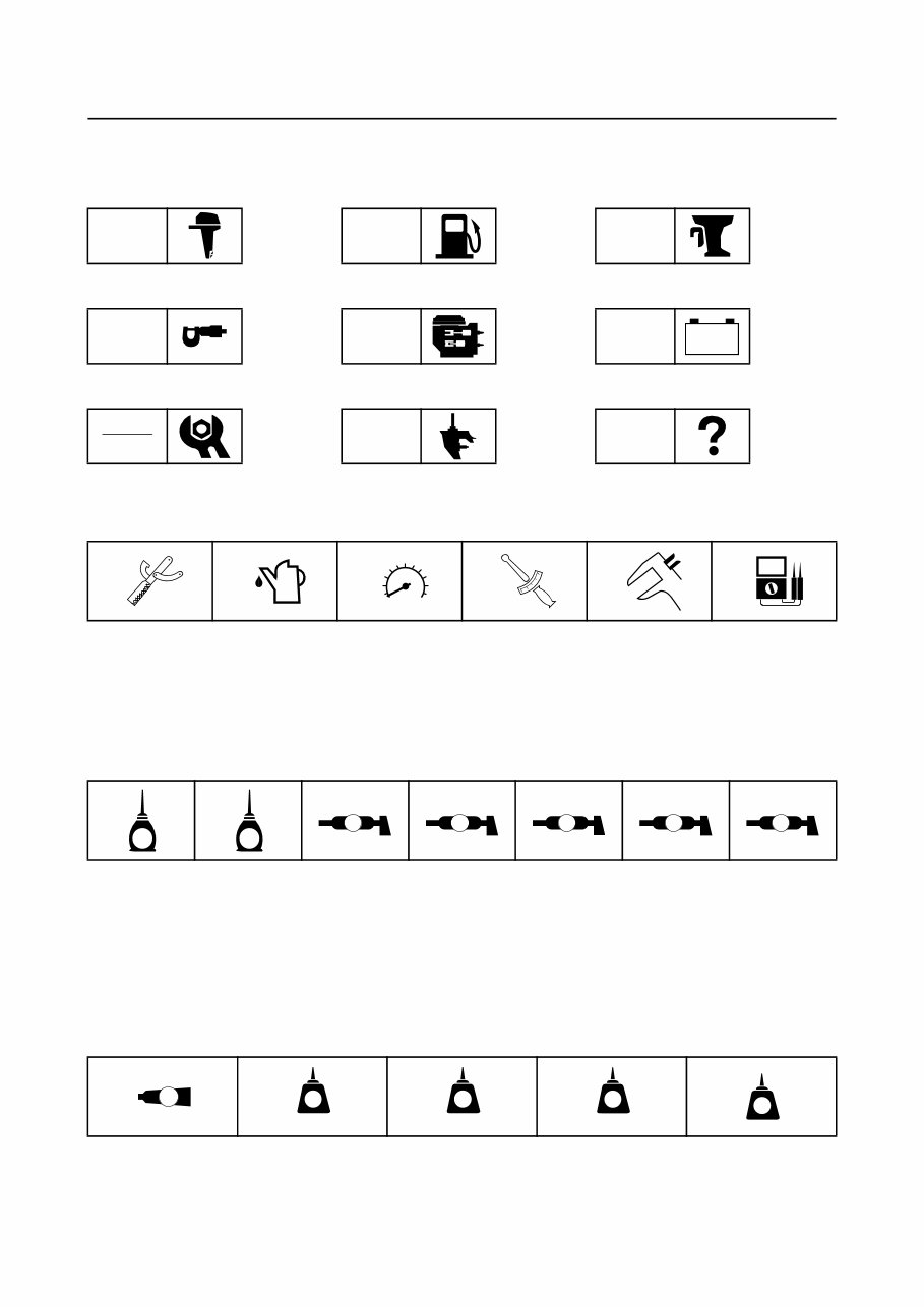
6C12G11 1-2 1 2 3 4 5 6 7 8 9 Symbols The symbols below are designed to indicate the content of a chapter. General information Specifications Periodic checks and adjustments Fuel system Power unit Lower unit Bracket unit Electrical systems Troubleshooting GEN INFO SPEC CHK ADJ FUEL POWR LOWR BRKT ELEC TRBL SHTG – + Symbols 1 to 6 indicate specific data. 1 Special tool 2 Specified oil or fluid 3 Specified engine speed 4 Specified tightening torque 5 Specified measurement 6 Specified electrical value (resistance, voltage, electric current) Symbols 7 to C in an exploded diagram indicate the grade of lubricant and the lubrication point. 7 Apply Yamaha 4-stroke motor oil 8 Apply gear oil 9 Apply water resistant grease (Yamaha grease A) 0 Apply molybdenum disulfide grease A Apply corrosion resistant grease (Yamaha grease D) B Apply low temperature resistant grease (Yamaha grease C) C Apply injector grease Symbols D to I in an exploded diagram indicate the type of sealant or locking agent and the appli- cation point. D Apply Gasket Maker E Apply LOCTITE 271 (red) F Apply LOCTITE 242 (blue) G Apply LOCTITE 572 H Apply silicon sealant 1 2 3 4 5 6 T R . . 7 8 9 0 A B C E G A M D C I D E F G H GM 271 LT 242 LT 572 LT SS How to use this manual
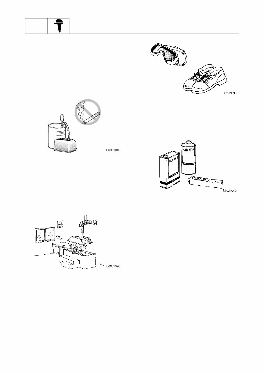
GEN INFO General information 1-3 6C12G11 Safety while working 1 To prevent an accident or injury and to ensure quality service, follow the safety pro- cedures provided below. Fire prevention Gasoline is highly flammable. Keep gasoline and all flammable products away from heat, sparks, and open flames. Ventilation Gasoline vapor and exhaust gas are heavier than air and extremely poisonous. If inhaled in large quantities they may cause loss of consciousness and death within a short time. When test running an engine indoors (e.g., in a water tank) be sure to do so where ade- quate ventilation can be maintained. Self-protection Protect your eyes by wearing safety glasses or safety goggles during all operations involv- ing drilling and grinding, or when using an air compressor. Protect your hands and feet by wearing pro- tective gloves and safety shoes when neces- sary. Parts, lubricants, and sealants Use only genuine Yamaha parts, lubricants, and sealants or those recommended by Yamaha, when servicing or repairing the out- board motor. Under normal conditions, the lubricants men- tioned in this manual should not harm or be hazardous to your skin. However, you should follow these precautions to minimize any risk when working with lubricants. 1. Maintain good standards of personal and industrial hygiene. 2. Change and wash clothing as soon as possible if soiled with lubricants. 3. Avoid contact with skin. Do not, for example, place a soiled rag in your pocket. 4. Wash hands and any other part of the body thoroughly with soap and hot water after contact with a lubricant or lubricant soiled clothing has been made. 5. To protect your skin, apply a protective cream to your hands before working on the outboard motor.
6C12G11 1-4 1 2 3 4 5 6 7 8 9 6. Keep a supply of clean, lint-free cloths for wiping up spills, etc. Good working practices Special service tools Use the recommended special service tools to protect parts from damage. Use the right tool in the right manner—do not improvise. Tightening torques Follow the tightening torque specifications provided throughout the manual. When tight- ening nuts, bolts, and screws, tighten the large sizes first, and tighten fasteners starting in the center and moving outward. Non-reusable parts Always use new gaskets, seals, O-rings, cot- ter pins, circlips, etc., when installing or assembling parts. Disassembly and assembly 1. Use compressed air to remove dust and dirt during disassembly. 2. Apply engine oil to the contact surfaces of moving parts before assembly. 3. Install bearings with the manufacture identification mark in the direction indi- cated in the installation procedure. In addition, be sure to lubricate the bearings liberally. 4. Apply a thin coat of water-resistant grease to the lip and periphery of an oil seal before installation. 5. Check that moving parts operate nor- mally after assembly. Identification 1 Applicable models This manual covers the following models. Applicable models F50TH, F50TR, T50TR, F60TH, F60TR, T60TR Safety while working / Identification
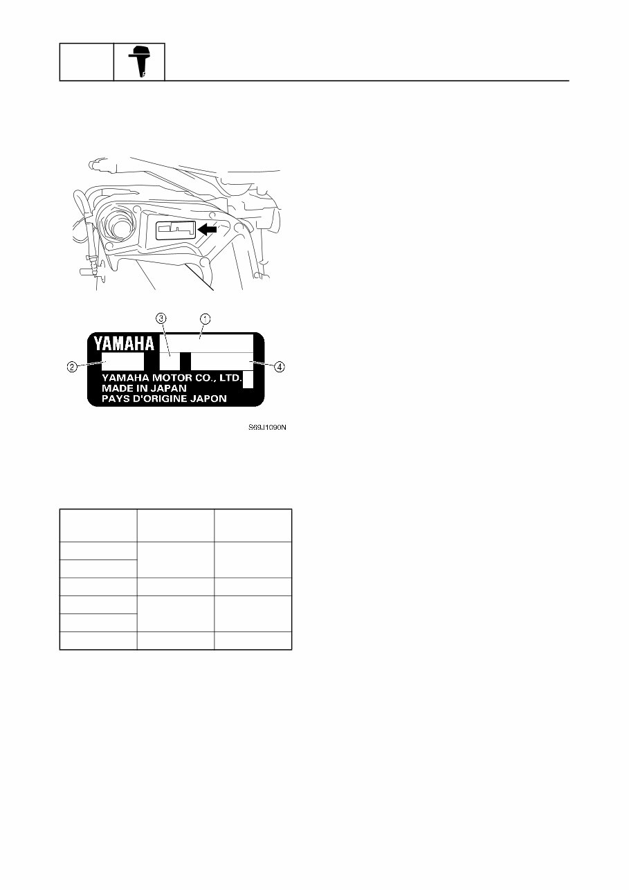
GEN INFO General information 1-5 6C12G11 Serial number The outboard motor serial number is stamped on a label attached to the port clamp bracket. 1 Model name 2 Approved model code 3 Transom height 4 Serial number Model name Approved model code Starting serial No. F50TH 6C1 1000001– F50TR T50TR 6C2 1000001– F60TH 6C5 1000001– F60TR T60TR 6C6 1000001– S6C11010
6C12G11 1-6 1 2 3 4 5 6 7 8 9 Outline of features 1 New electronic fuel injected F50 and F60 outboard motors have a mainly redesigned fuel and intake system based on the carbureted F60 outboard motor. S6C11120 Power unit • Single throttle body, single throttle valve • Multi-point injection system, group injection (#1/#4 and #2/#3) • Group ignition system (#1/#4 and #2/#3) • Large plastic intake manifold • Compact plastic fuel rail • Modularized intake system components • Vapor separator with built-in pressure regulator • Solenoid valve • Fuel cooler • Aluminum rocker arm Electrical • Compact electronic fuel injection system • Self-diagnosis system and Yamaha Diagnostic System • Variable trolling RPM switch (optional for tiller handle model) • Throttle position sensor with learning function (adjustment free) • Compact charging system at low rpm • Compact fuel injectors • Fuel filter with water separator Clamp bracket/upper case • 2-piece upper case • Upper portion case with oil sump • Big capacity water wall structure around muffler • Idle exhaust labyrinth structure • Exclusive clamp bracket for permanent mount- ing Lower unit • Same lower drive unit as carbureted F60 model Identification / Outline of features
GEN INFO General information 1-7 6C12G11 Features and benefits 1 Fuel system A pressure regulator is built into the vapor separator to obtain compact and simple fuel delivery structure. A plastic fuel rail is used to prevent it from corrosion and for light weight. Fuel discharged from the pressure regulator returns to the vapor separator after cooling down through the fuel cooler. The fuel joint is used on the high pressure fuel hose to remove and/or install the intake unit easily. S6C11130 Fuel filter (Optional) Fuel tank Fuel cooler Pressure regulator Primer pump Fuel filter with water separator Fuel pump (Mechanical) Fuel filter Vapor separator Electric fuel pump Fuel rail Fuel injector #1 #2 #3 #4 Fuel injector Fuel injector Fuel injector
2005 Yamaha 50HP 4-Stroke EFI High Thrust Outboards
2005 Yamaha 60HP 4-Stroke EFI High Thrust Outboards
2006 Yamaha 50HP 4-Stroke EFI High Thrust Outboards
2006 Yamaha 60HP 4-Stroke EFI High Thrust Outboards
2007 Yamaha 50HP 4-Stroke EFI High Thrust Outboards
2007 Yamaha 60HP 4-Stroke EFI High Thrust Outboards
2008 Yamaha 50HP 4-Stroke EFI High Thrust Outboards
2008 Yamaha 60HP 4-Stroke EFI High Thrust Outboards
2009 Yamaha 50HP 4-Stroke EFI High Thrust Outboards
2009 Yamaha 60HP 4-Stroke EFI High Thrust Outboards
After payment, MyGreenManuals.com is your number one source for repair manuals. Our informative repair manual, owner's manuals, and parts catalogs contain all the information you'll need to perform repairs, look up parts, or do routine maintenance on your machine. You will have access to information regarding the following topics:
General Information
Routine Maintenance
Engine Removal and Installation
Fuel System
Lubrication and Cooling System
Engine Specifications
Transmission, Drive Chain & Sprockets
Steering System
Shocks
Body Work
Intake & Exhaust
Electrical System
Advanced Troubleshooting
With our repair manuals, find the page pertaining to your job, print it off, and get working on your machine. No more ruining your expensive paper shop manual with grease and dirt.
Broke down on the trail or site and have a smartphone? What a cool way to find your problem and repair it on the trail, no downtime on the job site. With our repair manuals, you instantly have access to the material needed to get you running again. Kind of tough to do that with a paper manual.
And did we mention the fact that you're saving the trees? All our repair manuals come with a lifetime protection policy. If lost or damaged, simply contact us, and we'll replace it free of charge for life.
We provide various repair service manuals, workshop manuals, repair manuals, owners manuals, parts catalogs, and other various manuals, all in an electronic format.
UTVs, motorcycles, ATVs, quads, snowmobiles, Seadoo, equipment, small engines, inboards, outboards, and more.
* Instant access
* No shipping cost
* Get a download so no waiting, repair it now
If you are looking for a specific manual and cannot find it or do not see it listed, then contact our customer support team via the contact us link above with details of the required manual, and we will do our absolute best to find and list it for you.