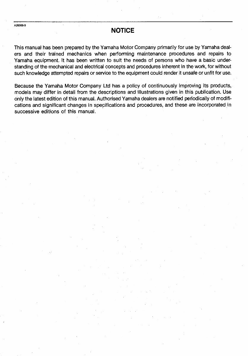
A20000-0 NOTICE This manual has been prepared by the Yamaha Motor Company primarily for use by Yamaha deal- ers and their trained mechanics when performing maintenance procedures and repairs to Yamaha equipment. It has been written to suit the needs of persons who have a basic under- standing of the mechanical and electrical concepts and procedures inherent in the work, for without such knowledge attempted repairs or service to the equipment could render it unsafe or unfit for use. Because the Yamaha Motor Company Ltd has a policy of continuously improving its products, models may differ in detail from the descriptions and illustrations given in this publication. Use only the latest edition of this manual. Authorised Yamaha dealers are notified periodically of modifi- cations and significant changes in specifications and procedures, and these are incorporated in successive editions of this manual.
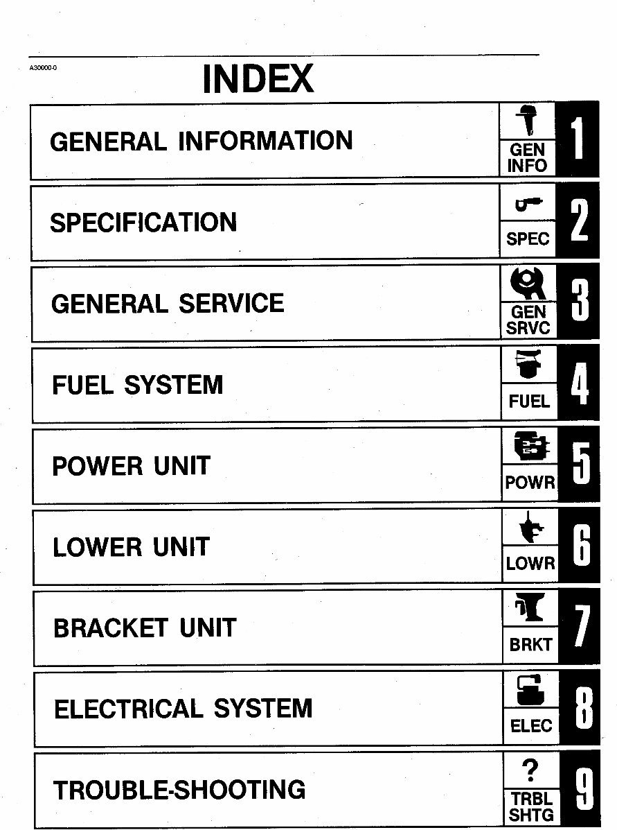
A30000.-0 INDEX GENERAL INFORMATION SPECIFICATION SPEC GENERAL SERVICE FUEL SYSTEM fit GEN SRVC FUEL POWER UNIT if= POWR LOWER UNIT LOWR BRACKET UNIT I ELECTRICAL SYSTEM TROUBLE-SHOOTING '7 TRBL SHTG
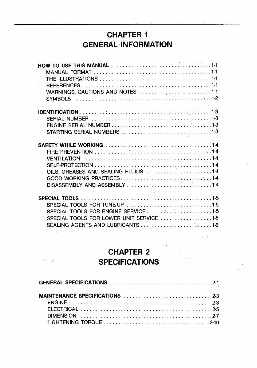
CHAPTER 1 GENERAL INFORMATION HOW TO USE THIS MANUAL ................................... 1-1 MANUAL FORMAT ......................................... 1-1 THE ILLUSTRATIONS ....................................... 1-1 REFERENCES ............................................. 1-1 WARNINGS, CAUTIONS AND NOTES .......................... 1-1 SYMBOLS ................................................ 1-2 IDENTIFICATION ......... : .................................... 1-3 SERIAL NUMBER .......................................... 1-3 ENGINE SERIAL NUMBER ................................... 1-3 STARTING SERIAL NUMBERS ................................ 1-3 SAFETY WHILE WORKING ...................................... 1-4 FIRE PREVENTION ......................................... 1.4 VENTILATION ............................................. 1-4 SELF-PROTECTION ......................................... 1-4 OILS, GREASES AND SEALING FLUIDS ....................... 1-4 GOOD WORKING PRACTICES ................................ 1-4 DISASSEMBLY AND ASSEMBLY .............................. 1-4 SPECIAL TOOLS ........................... ................... 1-5 SPECIAL TOOLS FOR TUNE-UP .............................. 1-5 SPECIAL TOOLS FOR ENGINE SERVICE ................ ....... 1-5 SPECIAL TOOLS FOR LOWER UNIT SERVICE .................. 1-6 SEALING AGENTS AND LUBRICANTS ......................... 1-6 CHAPTER 2 SPECIFICATIONS GENERAL SPECIFICATIONS .................................... 2-1 MAINTENANCE SPECIFICATIONS ............................... 2-3 ENGINE .................................................. 2-3 ELECTRICAL .............................................. 2-5 DIMENSION ............................................... 2-7 TIGHTENING TORQUE ..................................... 2-10
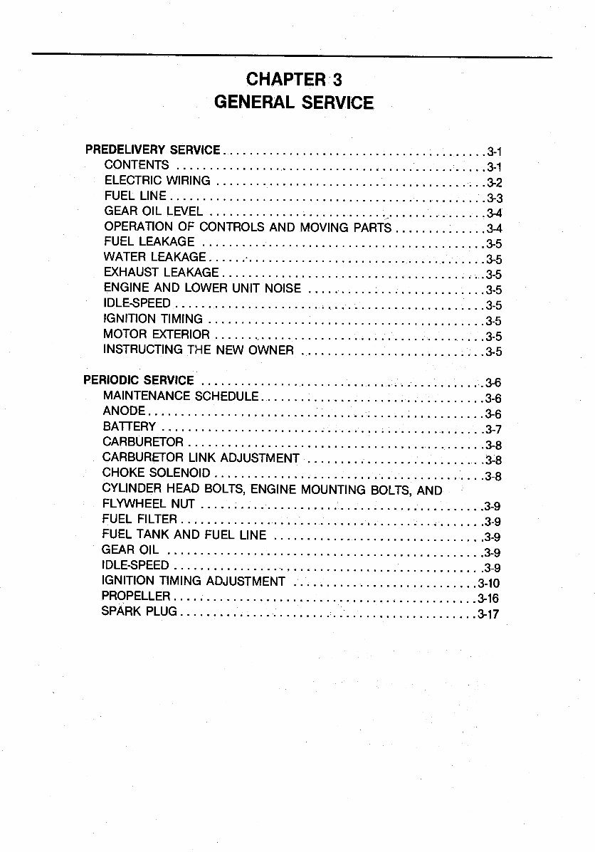
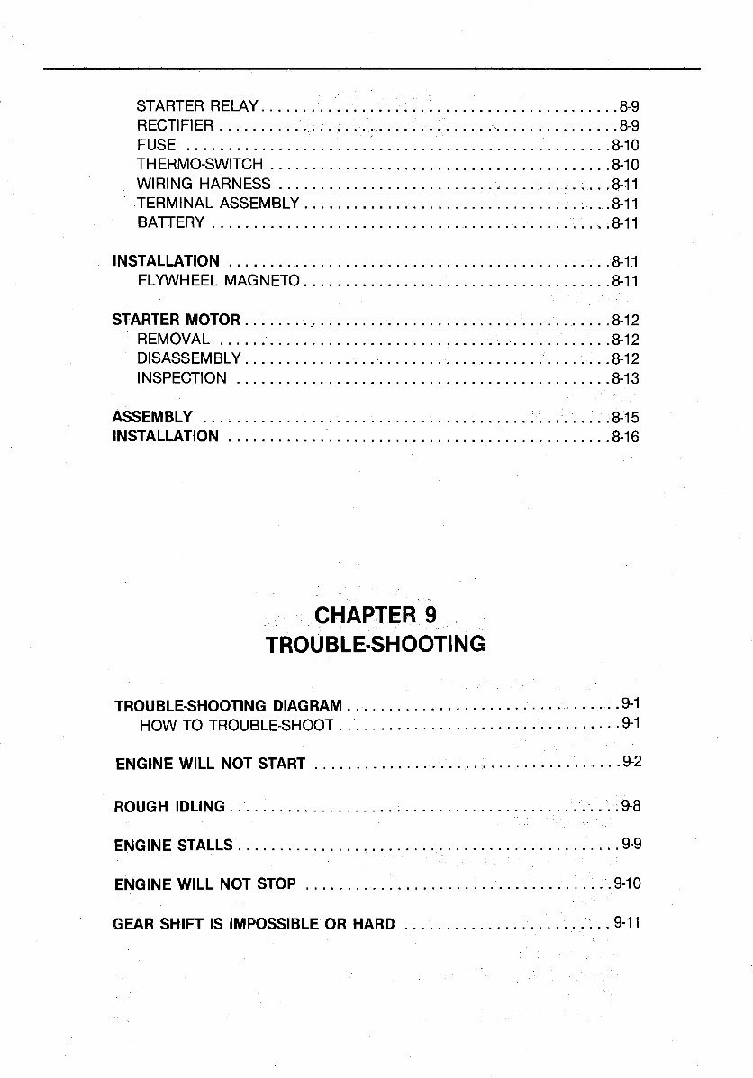
CHAPTER 3 GENERAL SERVICE PREDELIVERY SERVICE ........................................ 3-1 CONTENTS ............................................... 3-1 ELECTRIC WIRING ......................................... 3-2 FUEL LINE ................................................ 3.3 GEAR OIL LEVEL .......................................... 3.4 OPERATION OF CONTROLS AND MOVING PARTS .............. 3-4 FUEL LEAKAGE ........................................... 3-5 WATER LEAKAGE ...... ..................................... 3-,5 EXHAUST LEAKAGE ........................................ 3-5 ENGINE AND LOWER UNIT NOISE ............................ 3-5 IDLE.SPEED ................................................ 3-5 IGNITION TIMING .......................................... 3-5 MOTOR EXTERIOR ............................ .............. 3-5 INSTRUCTING THE NEW OWNER ............................ 3-5 PERIODIC SERVICE ........................................... 3-6 MAINTENANCE SCHEDULE ................................... 3-6 ANODE .................................................... 3-6 BA'I-I'ERY ................................................. 3-7 CARBURETOR .............................................. 3-8 CARBURETOR LINK ADJUSTMENT ............................ 3-8 CHOKE SOLENOID ......................................... 3-8 CYLINDER HEAD BOLTS, ENGINE MOUNTING BOLTS, AND FLYWHEEL NUT ............................................ 3-9 FUEL FILTER ............................................... 3-9 FUEL TANK AND FUEL LINE ................................ 3-9 GEAR OIL ................................................ 3-9 IDLE-SPEED ................................................ 3-9 IGNITION TIMING ADJUSTMENT ............................ 3-10 PROPELLER .............................................. 3-16 SPARK PLUG ....................... ...................... 3-17
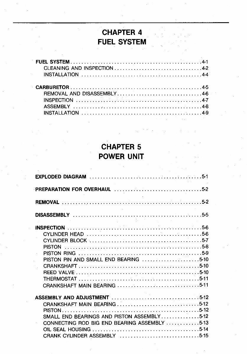
CHAPTER 4 FUEL SYSTEM FUEL SYSTEM ................................................ 4-1 CLEANING AND INSPECTION ................................ 4-2 INSTALLATION ............................................ 4-4 CARBURETOR ................................................ 4-5 REMOVAL AND DISASSEMBLY ............................... 4-6 INSPECTION .............................................. 4-7 ASSEMBLY ........... , .................................... 4-8 INSTALLATION ............................................. 4-9 CHAPTER 5 POWER UNIT EXPLODED DIAGRAM ......................................... 5-1 PREPARATION FOR OVERHAUL ................................ 5-2 REMOVAL ................................................... 5-2 DISASSEMBLY ............................................... 5-5 INSPECTION ................. ................................ 5-6 CYLINDER HEAD .......................................... 5-6 CYLINDER BLOCK ......................................... 5-7 PISTON .................................................. 5-8 PISTON RING ............................................. 5-9 PISTON PIN AND SMALL END BEARING ..................... 5-10 CRANKSHAFT ............................................ 5-10 REED VALVE ............................................. 5-10 THERMOSTAT ............................................ 5-11 CRANKSHAFT MAIN BEARING .............................. 5-11 ASSEMBLY AND ADJUSTMENT ................................. 5-12 CRANKSHAFT MAIN BEARING .............................. 5-12 PISTON .................................................. 5-12 SMALL END BEARINGS AND PISTON ASSEMBLY .............. 5-12 CONNECTING ROD BIG END BEARING ASSEMBLY ............ 5-13 OIL SEAL HOUSING ....................................... 5-14 CRANK CYLINDER ASSEMBLY ............................. 5-15
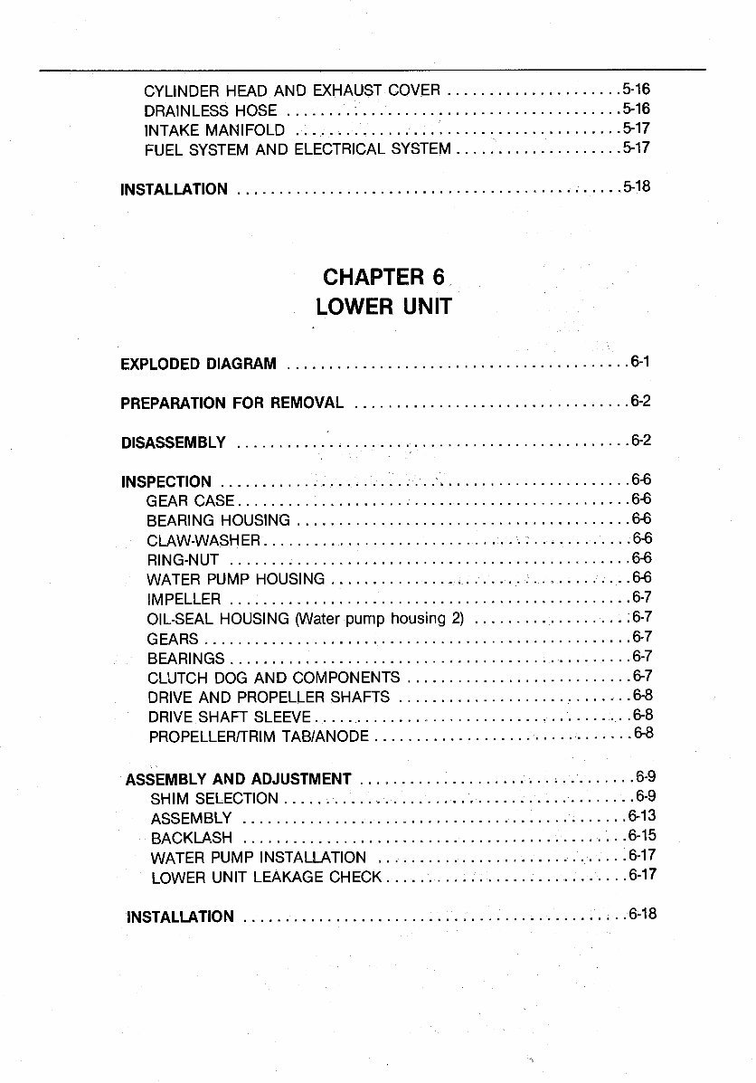
CYLINDER HEAD AND EXHAUST COVER ..................... 5-16 DRAINLESS HOSE .5-16 INTAKE MANIFOLD . ...... ....... .. : . ..................... 5-17 FUEL SYSTEM AND ELECTRICAL SYSTEM ............... ..... 5-17 INSTALLATION .......................................... .... 5-18 CHAPTER 6 LOWER UNIT EXPLODED DIAGRAM ......................................... 6-1 PREPARATION FOR REMOVAL ................................. 6-2 DISASSEM BLY .............. ......... ............................ 6-2 INSPECTION .................. . .. .... ........................... 6-6 GEAR CASE ............................................... 6-6 BEARING HOUSING ........................................ 6-6 CLAW-WASH ER ............................ . ... .......... ,. 6-6 RING-NUT ................................................ 6-6 WATER PUMP HOUSING ...................................... 6-6 IMPELLER ................................................ 6-7 OIL-SEAL HOUSING (Water pump housing 2) .................. :6-7 G EARS ................................................... 6-7 BEARINGS ................................................. 6-7 CLUTCH DOG AND COMPONENTS ........................... 6-7 DRIVE AND PROPELLER SHAFTS ............................ 6-8 DRIVE SHAFT SLEEVE ....................................... 6-8 PROPELLER/TRIM TAB/ANODE ................................ 6-8 ASSEMBLY AND ADJUSTMENT .................................. 6-9 SHIM SELECTION .......................................... 6-9 ASSEMBLY .............................................. 6-13 BACKLASH .............................................. 6-15 WATER PUMP INSTALLATION .............................. 6-17 LOWER UNIT LEAKAGE CHECK ............................. 6-17 INSTALLATION .............................................. 6-t8
1992 Yamaha 55HP 2-Stroke Outboards Service & Repair Manual
Models covered:
C55ELRP
C55ELRQ
C55ELRR
C55ELRS
C55ELRT
C55TLRS
C55TLRT
Whether you're a professional mechanic or a DIY enthusiast, this repair manual equips you with the necessary troubleshooting and replacement procedures recommended by the manufacturer. It includes step-by-step instructions, clear images, and exploded-view illustrations to assist in fixing outboard problems.
Regular maintenance is essential for your outboard's longevity, and over time, certain parts will require replacement. A reliable repair manual provides manufacturer-recommended troubleshooting charts and replacement procedures, enabling you to address issues promptly and efficiently.
Please note:
This is not a generic repair manual but the official manual used by professional technicians. It encompasses every troubleshooting and replacement procedure provided by the manufacturer, featuring step-by-step instructions, exploded-view illustrations, and clear images.
Accessible in digital format, this manual eliminates the hassle of searching through numerous pages and offers the convenience of portability, searchability, and bookmarking. It is also printable for those who prefer physical copies.
Printable: Yes Language: English Compatibility: Compatible with various electronic devices, including PC & Mac computers, Android and Apple smartphones & tablets, etc. Requirements: Adobe Reader (free)




 Lifetime Access




