Contents General information 1 GEN INFO Specifications 2 SPEC Periodic checks and adjustments 3 CHK ADJ Fuel system 4 FUEL Power unit 5 POWR Lower unit 6 LOWR Bracket unit 7 BRKT Electrical systems 8 ELEC Index – +
62Y3A11 GEN INFO 1 2 3 4 5 6 7 8 I General information How to use this manual ................................................................................. 1-1 Manual format............................................................................................ 1-1 Symbols ..................................................................................................... 1-2 Safety while working...................................................................................... 1-3 Fire prevention........................................................................................... 1-3 Ventilation .................................................................................................. 1-3 Self-protection ........................................................................................... 1-3 Parts, lubricants, and sealants .................................................................. 1-3 Good working practices ............................................................................. 1-4 Disassembly and assembly ....................................................................... 1-4 Identification ................................................................................................... 1-5 Applicable models ..................................................................................... 1-5 Serial number ............................................................................................ 1-5 Features and benefits .................................................................................... 1-6 Newly designed four carburetors ............................................................... 1-6 CDI unit with microcomputer ..................................................................... 1-7 Lower unit .................................................................................................. 1-8 Technical tips ............................................................................................... 1-10 Carburetor ............................................................................................... 1-10 Acceleration pump ................................................................................... 1-15 Ignition system......................................................................................... 1-17 Ignition timing control ............................................................................... 1-19 Power trim and tilt .................................................................................... 1-22 Propeller selection ....................................................................................... 1-32 Propeller size ........................................................................................... 1-32 Selection .................................................................................................. 1-32 Predelivery checks ...................................................................................... 1-33 Checking the fuel system ........................................................................ 1-33 Checking the gear oil ............................................................................... 1-33 Checking the engine oil ........................................................................... 1-33 Checking the battery................................................................................ 1-33 Checking the outboard motor mounting position ..................................... 1-34 Checking the remote control cables ........................................................ 1-34 Checking the steering wheel/tiller handle ................................................ 1-34 Checking the gearshift and throttle operation .......................................... 1-34 Checking the tilt system........................................................................... 1-35 Checking the engine start switch and engine stop switch/engine shut-off switch ............................................. 1-35 Checking the pilot water outlet ................................................................ 1-35 Test run ................................................................................................... 1-35 Break-in ................................................................................................... 1-36 After test run ............................................................................................ 1-36
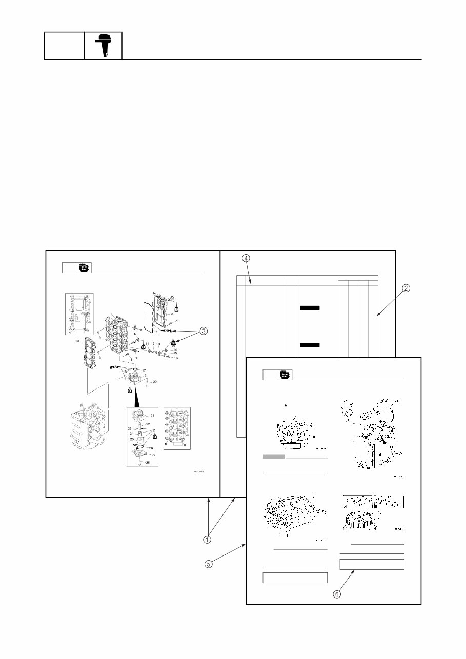
GEN INFO General information 1-1 62Y3A11 How to use this manual 1 Manual format The format of this manual has been designed to make service procedures clear and easy to under- stand. Use the information below as a guide for effective and quality service. 1 Parts are shown and detailed in an exploded diagram and are listed in the components list. 2 Tightening torque specifications are provided in the components list at the beginning of each section and after a numbered step with tightening instructions. 3 Symbols are used to indicate important aspects of a procedure, such as the grade of lubricant and lubrication point. 4 The components list consist of parts and part quantities, as well as bolt and screw dimensions. 5 Service points regarding removal, checking, and installation are shown in individual illustrations to explain the relevant procedure. 6 This service manual has two types of special service tools. Use part numbers that start with “J-”, “YB-”, “YM-”, “YS-”, “YU-”, “YW-”, or “YX-” for USA and Canada. Use parts numbers that start with “90890-” for all other countries. POWR Power unit 5-35 62Y1A11 Cylinder head 62Y1A11 È Tightening sequence No. Part name Q’ty Remarks Tightening torques Stage N·m kgf·m ft·lb 1 Cylinder head 1 2 Oil p um p 1 3 Cylinder head cover 1 4 Bolt 7 M6 × 20 mm 5 Cylinder head cover gasket 1 Not reusable 6 Bolt 10 M9 × 95 mm 1st 2nd 23 47 2.3 4.7 17 34 7 Spark plug 4 18 1.8 13 8 Bolt 5 M6 × 25 mm 1st 2nd 6 12 0.6 1.2 4.3 8.7 9 Dowel pin 2 10 Cylinder head gasket 1 Not reusable 11 Grommet 4 12 Anode 4 13 14 15 16 17 18 19 20 21 22 23 24 25 26 27 28 Cylinder head POWR Power unit 5-31 62Y1A11 Removing the timing belt and sprockets 1. Set the cylinder #1 piston position to TDC of the compression stroke by align- ing the “1” mark a on the driven sprocket with the “ ” mark b on the cylinder head. CAUTION: Do not turn the drive sprocket counter- clockwise, otherwise the valve system may be damaged. 2. Remove the breather hose and loosen the drive sprocket nut 1. NOTE: • Use a deep socket 2 (M42) for this proce- dure. • Do not turn the camshaft when loosening the drive sprocket nut. 3. Remove the tensioner 4 and timing belt 5 from the driven sprocket side. 4. Loosen the driven sprocket bolt 6 and remove the driven sprocket . È For USA and Canada É For worldwide NOTE: Do not turn the camshaft when loosening the driven sprocket bolt. Crankshaft holder 3: YB-06562 Crankshaft holder 18 3: 90890-06562 Flywheel magnet holder: YB-06139 Flywheel holder: 90890-06522
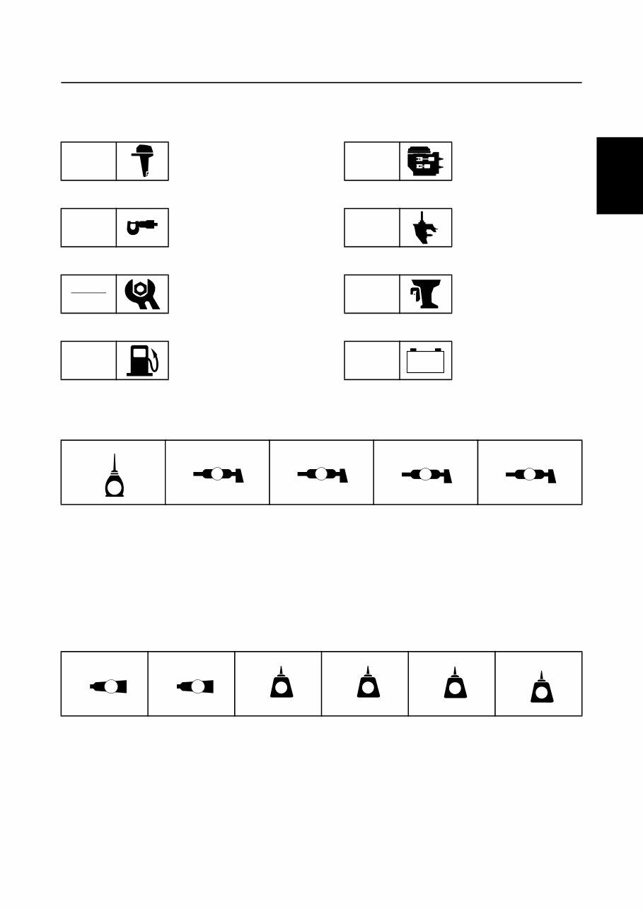
62Y3A11 1-2 1 2 3 4 5 6 7 8 I Symbols The symbols below are designed to indicate the content of a chapter. General information Specifications Periodic checks and adjustments Fuel system Power unit Lower unit Bracket unit Electrical systems Symbols 1 to 5 in an exploded diagram indicate the grade of lubricant and the lubrication point. 1 Apply Yamaha 4-stroke motor oil 2 Apply water resistant grease (Yamaha grease A, Yamaha marine grease) 3 Apply molybdenum disulfide grease 4 Apply anti-corrosion grease (Yamaha grease D) 5 Apply low temperature resistant grease (Yamaha grease C) Symbols 6 to A in an exploded diagram indicate the type of sealant or locking agent and the appli- cation point. 6 Apply Gasket Maker ® 7 Apply Yamabond No. 4 8 Apply LOCTITE ® No. 271 (Red LOCTITE) 9 Apply LOCTITE ® No. 242 (Blue LOCTITE) 0 Apply LOCTITE ® No. 572 A Apply silicon sealant GEN INFO SPEC CHK ADJ FUEL POWR LOWR BRKT ELEC – + 1 2 3 4 5 6 7 8 9 0 A E A M D C GM 4 271 LT 242 LT 572 LT SS How to use this manual
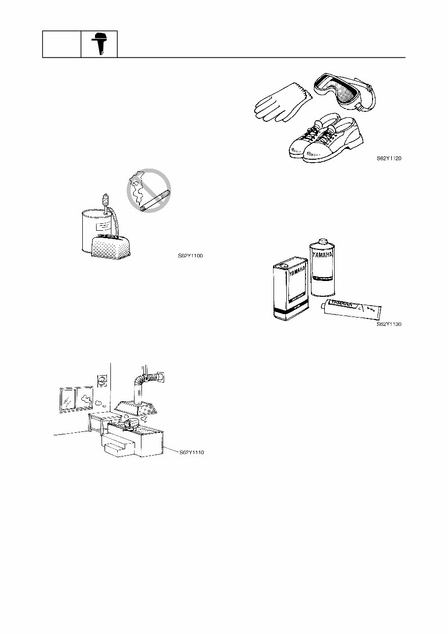
GEN INFO General information 1-3 62Y3A11 Safety while working 1 To prevent an accident or injury and to ensure quality service, follow the safety pro- cedures provided below. Fire prevention Gasoline is highly flammable. Keep gasoline and all flammable products away from heat, sparks, and open flames. Ventilation Gasoline vapor and exhaust gas are heavier than air and extremely poisonous. If inhaled in large quantities they may cause loss of consciousness and death within a short time. When test running an engine indoors (e.g., in a water tank) be sure to do so where ade- quate ventilation can be maintained. Self-protection Protect your eyes by wearing safety glasses or safety goggles during all operations involv- ing drilling and grinding, or when using an air compressor. Protect your hands and feet by wearing pro- tective gloves and safety shoes when neces- sary. Parts, lubricants, and sealants Use only genuine Yamaha parts, lubricants, and sealants or those recommended by Yamaha, when servicing or repairing the outboard motor. Under normal conditions, the lubricants men- tioned in this manual should not harm or be hazardous to your skin. However, you should follow these precautions to minimize any risk when working with lubricants. 1. Maintain good standards of personal and industrial hygiene. 2. Change and wash clothing as soon as possible if soiled with lubricants. 3. Avoid contact with skin. Do not, for example, place a soiled rag in your pocket. 4. Wash hands and any other part of the body thoroughly with soap and hot water after contact with a lubricant or lubricant soiled clothing has been made. 5. To protect your skin, apply a protective cream to your hands before working on the outboard motor.
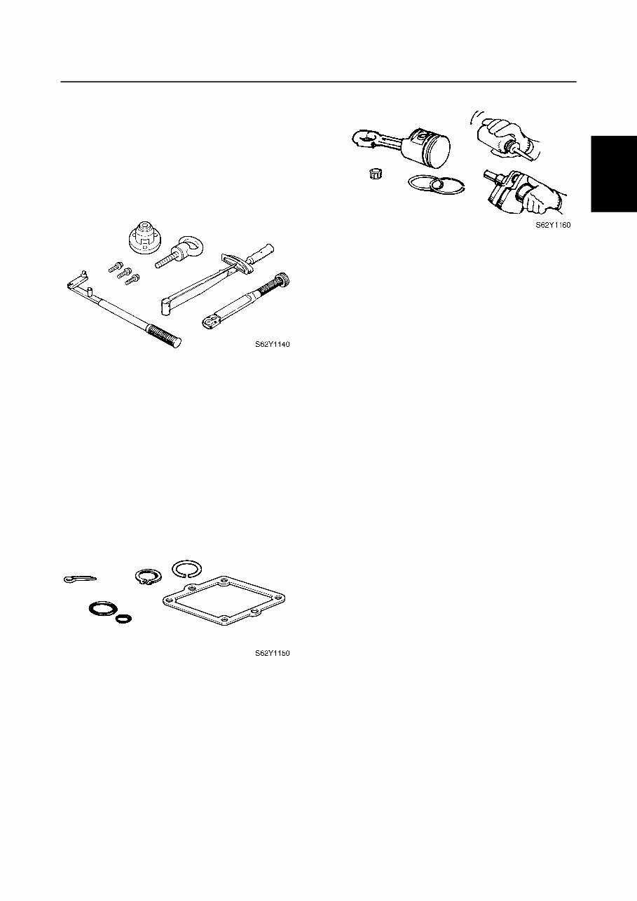
62Y3A11 1-4 1 2 3 4 5 6 7 8 I 6. Keep a supply of clean, lint-free cloths for wiping up spills, etc. Good working practices Special tools Use the recommended special tools to pro- tect parts from damage. Use the right tool in the right manner—do not improvise. Tightening torques Follow the tightening torque specifications provided throughout the manual. When tight- ening nuts, bolts, and screws, tighten the large sizes first, and tighten fasteners starting in the center and moving outward. Non-reusable parts Always use new gaskets, seals, O-rings, cot- ter pins, circlips, etc., when installing or assembling parts. Disassembly and assembly 1. Use compressed air to remove dust and dirt during disassembly. 2. Apply engine oil to the contact surfaces of moving parts before assembly. 3. Install bearings with a manufacture iden- tification mark in the direction indicated in the installation procedure. In addition, be sure to lubricate the bearings liberally. 4. Apply a thin coat of water-resistant grease to the lip and out periphery of an oil seal before installation. 5. Check that moving parts operate nor- mally after assembly. Safety while working
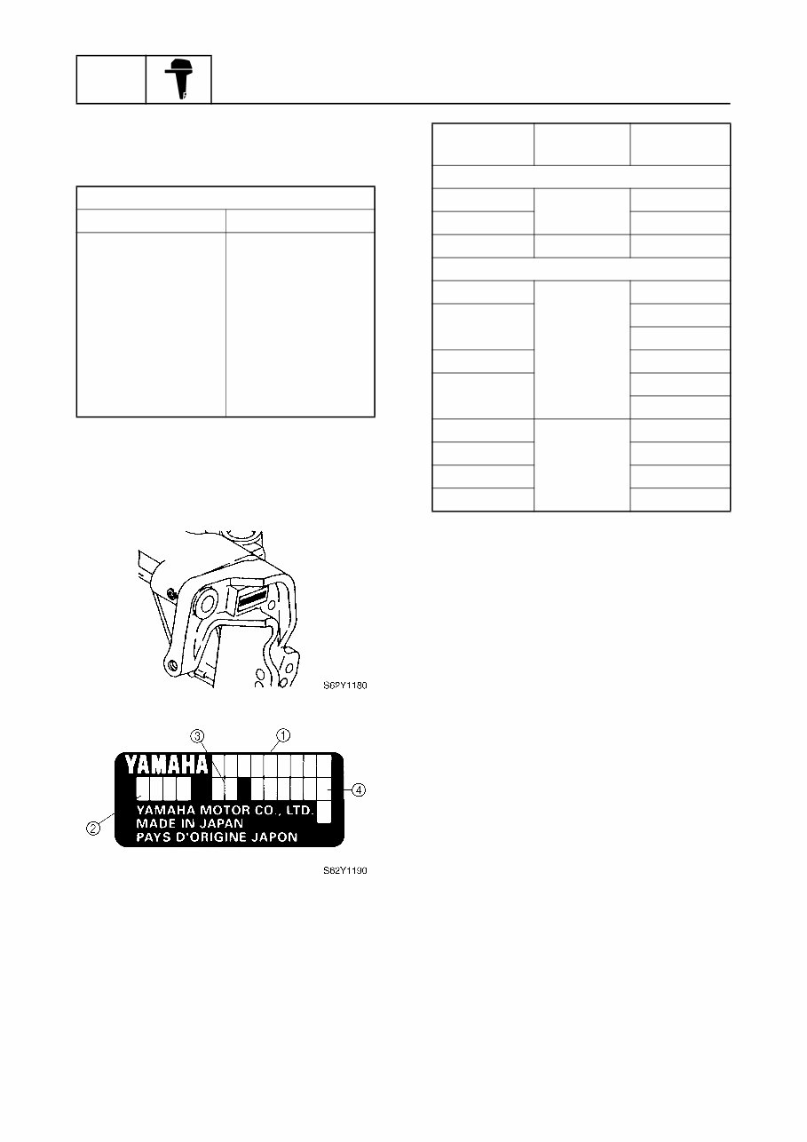
GEN INFO General information 1-5 62Y3A11 Identification 1 Applicable models This manual covers the following models. Serial number The outboard motor serial number is stamped on a label attached to the port clamp bracket. 1 Model name 2 Approved model code 3 Transom height 4 Serial number Applicable models USA, Canada Worldwide — F50AEHD F50TH F50AEHT — F50AED F50TR F50AET T50TR FT50BET — FT50CEHD — FT50CED — FT50CET Model name Approved model code Starting serial No. USA, Canada F50TH 62Y L: 451812– F50TR L: 421732– T50TR 64J L: 406850– Worldwide F50AEHD 62Y L: 350505– F50AEHT L: 451812– X: 750469– F50AED L: 301090– F50AET L: 421626– X: 700700– FT50BET 64J L: 406850– FT50CEHD L: 650101– FT50CED L: 550101– FT50CET L: 450101–
This factory service/repair/workshop manual is designed for the Yamaha F50A, FT50B, and FT50C outboard models. It contains comprehensive maintenance and repair procedures, allowing you to service, diagnose, and repair your outboard engine with ease. The manual features step-by-step instructions, highly detailed exploded diagrams, and pictures to facilitate correct and efficient completion of all repair procedures. It covers general information, specifications, periodic checks and adjustments, fuel system, power unit, lower unit, bracket unit, electrical systems, and includes an index for easy reference.
Applicable Models:
Yamaha F50A Outboard
Yamaha FT50B Outboard
Yamaha FT50C Outboard
Part Number: 62Y-28197-3A-11
This manual is available in digital format, ensuring instant access without any shipping costs or waiting for physical delivery. Upon payment completion through our secure processor, you will receive the manual today. It is compatible with all versions of Windows and Mac, and can be printed for convenience.