PREFACE This Supplementary Service Manual has been prepared to introduce the modification and additional information for the F40A, F45A, F50A and FTSOB. Also, new information for F50Z and TSOZ based on F40A, F45A, F50A and FT50B is included. For complete service informa- tion and procedures, it is necessary to add the following manual with the corresponding sec- tions in this Supplementary Service Manual. .F40A, F45A, F50A, FT50B SERVICE MANUAL: 62Y-28197-ZA-C1 F50Z, T50Z • SUPPLEMENTARY SERVICE MANUAL @2000 by Yamaha Motor Co., Ltd. 1st Edition, September 2000 All rights reserved. Any reprinting or unauthorized use without the written permission of Yamaha Motor Co., Ltd. is expressly prohibited, Printed in Japan
HOW TO USE THIS MANUAL MANUAL FORMAT All of the procedures in this manual are organized in a sequential, step-by-step format. The information has been compiled to provide the mechanic with an easy to read, handy refer- ence that contains comprehensiveexplanations of all disassembly, repair, assembly, and check operations. In this revised format, the condition of a faulty component will precede an arrow symbol and the course of action required will follow the symbol, e.g., • Bearings Pitting/scratches--_ Replace. To assist you in finding your way through this manual, the section title and major heading is given at the top of every page. ILLUSTRATIONS The illustrations within this service manual represent all of the designated models. CROSSREFERENCES The cross references have beenkept to a minimum. Cross references will direct you to the appropriate section or chapter.
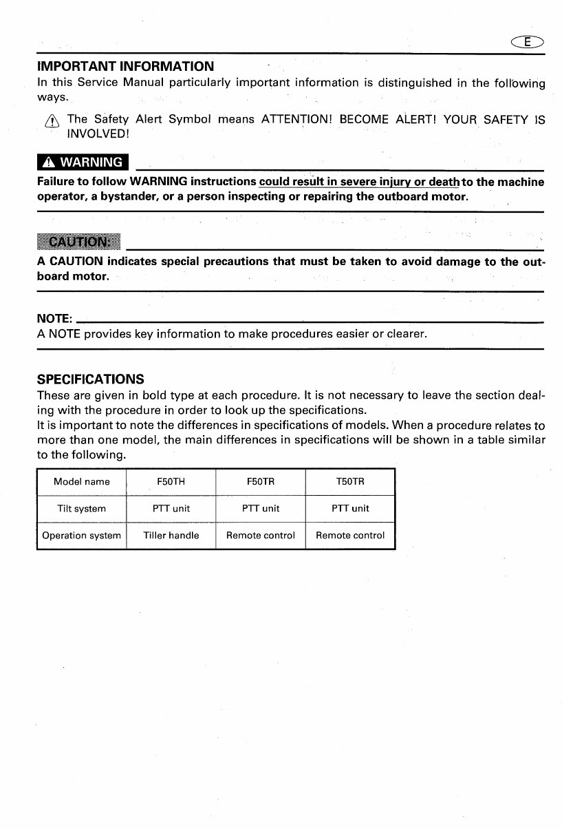
IMPORTANT INFORMATION In this Service Manual particularly important information is distinguished in the following ways. . _,_ ....... The Safety Alert Symbol means ATTENTION! BECOME ALERT! YOUR SAFETY IS INVOLVED! _.v_vAvg±w It k'_ll k.'_ [ell " Failure to follow WARNING instructions could result in severe injury or death to the machine operator, a bystander, or a person inspecting or repairing the outboard motor. A CAUTION indicates special precautions that must be taken to avoid damage to the out- board motor. NOTE: A NOTE provides key information to make procedures easier or clearer. SPECIFICATIONS These are given in bold type at each procedure. It is not necessary to leave the section deal- ing with the procedure in order to look up the specifications. It is important to note the differences in specifications of models. When a procedure relates to more than one model, the main differences in specifications will be shown in a table similar to the following. Model name F50TH F50TR T50TR Tilt system PTTunit PTTunit PTTunit Operation system Tiller handle Remotecontrol Remotecontrol
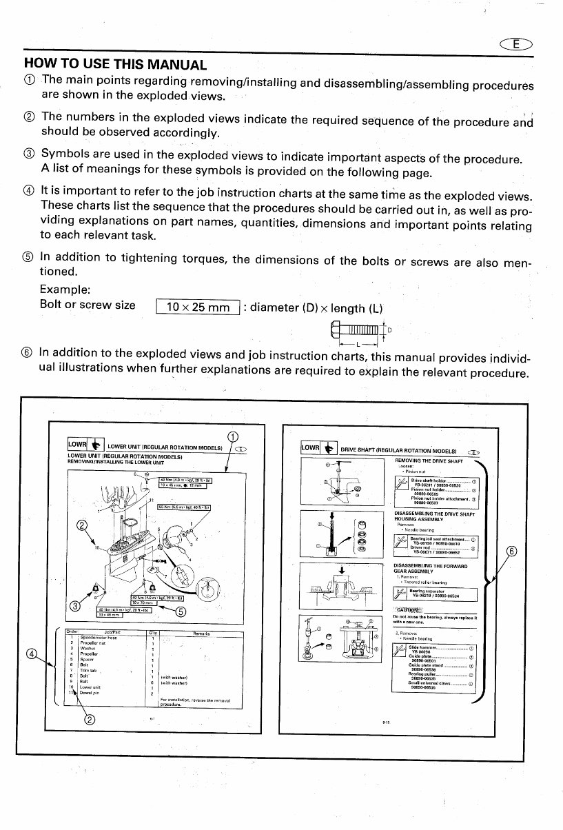
HOW TO USE THIS MANUAL _) The main points regarding removing/installing and disassembling/assembling procedures are shown in the exploded views. Q The numbers in the exploded views indicate the required sequence of the procedure and should be observed accordingly. Q Symbols are used in the exploded views to indicate important aspects of the procedure. A list of meanings for these symbols is provided on the following page. Q It is important to refer to the job instruction charts at the same time as the exploded views. These charts list the sequence that the procedures should be carried out in, as well as pro- viding explanations on part names, quantities, dimensions and important points relating to each relevant task. @ In addition to tightening torques, the dimensions of the bolts or screws are also men- tioned. _. Example" Bolt or screw size ] 10 x 25 mm I" diameter (D) × length (L) IllJlJlJllll o r. L -It @ In addition to the exploded views and job instruction charts, this manual provides individ- ual illustrations when further explanations are required to explain the relevant procedure. w.II. "OWE. O°,*,.EOU'...OT.T,O. MOOEL. O.,VES.'FT,"EOO....OTAT,O LOWER UNIT IREGULAR ROTATION MODELS) REMOVING THE DRIVE SHAFT REMOViNGtiNSTALUNG THE LOWER UNiT I _ ....... • Pinion nut Pinion nut holder ................. :.:.. @ 90890-06505 Pinion nut holder attachment. (_) /11 90890-g6507 J55Nm(5.5m• kgf,40ft.Fb) J DISASSEMBLING THE DRIVE SHAFT / HOUSING ASSEMBLY Q .............. "_B-06196 / 90S90-06610 Driver rod ..................................(_ I_ VB-06071/ 90890-06052 DISASSEMBLING THE FORWARD / ,_ GEAR ASSEMBLY / • Taoered rorler bearing _' _J Bearingseparator g r J * rn(4.0m- kgf, 29 R-'-Ib) 1_ 'cAe_l_'2_ rl0×45 rnm I Do not reusethe bearing, always replace it ---- 2, Remove: ' _)rder Job/Part Q'ty Remarks (_ •Needle bearing 1 Speedometer hose 1 2 Propeller nut 1 _" J_J .' _ Slide hammer ............................ YB-06096 3 Washer 1 Guide plate ................................ Q 4 Propeller 1 i, . 90890-06501 5 Spacer 1 - Guide plate stand..................... _L. 6 Bolt 1 90890-06538 7 Trimtab , 1 Bearingpuller............................ 8 ' Bolt 1 (W_th washer) 90890-06535 Small universalclaws .............. O Bolt 6 (with washer) 90890-06536 Lower unit 1 11_ Dowelpin 2 ._ k For installation, reversetheremoval procedure.
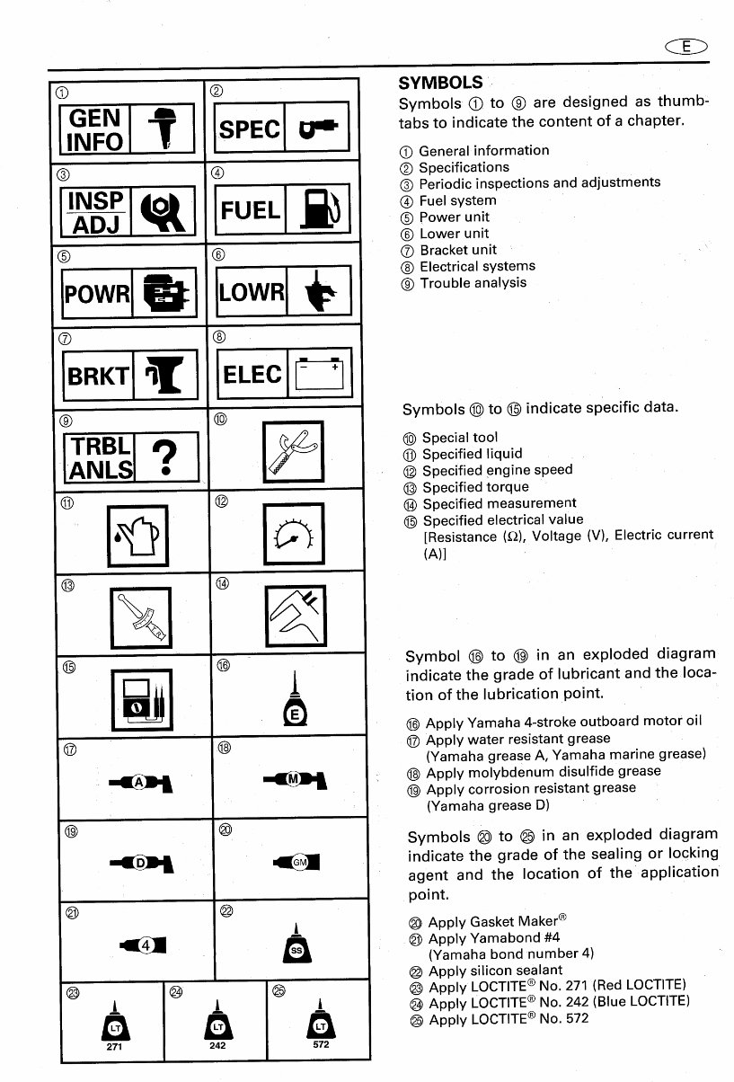
@ ® SYMBOLS _ GEN Symbols @ to @ are designed as thumb- INFO _ SPEC _111.,, tabs to indicate the content of a chapter. [7 O General information (_ Q Q Specifications : r INSP...._ _ j_l @Periodic inspections and adjustments _-_-i FUEL _ Q Fuel system @ Power unit ........ O Lower unit O ® O Bracket unit i _ _p @ Electrical systems POWR LOWR ® Trouble analysis ii i ul uu, ® ® I" I BRKT ELEC , I ® ® , Symbols @ to @ indicate specific data. TRBL _l 4_ ® Special tool @ Specified liquid ANLS , @ Specified engine speed @Specified to rque @ ....... @ (_) Specified measurement ' 6_) _ @ Specified electrical value [Resistance (,Q), Voltage (V), Electric current (A)] ® ® IIII II I ® ® .... Symbol @ to @ in an exploded diagram l_ij _ indicate the grade of lubricant and the:,loca- tion of the lubrication point. (_ Apply Yamaha 4-stroke outboard motor oil O O @ Apply water resistant grease (Yamaha grease A, Yamaha marine grease) , _ _ : @ Apply molybdenum disulfide grease @ Apply corrosion resistant grease • (Yamaha grease D) ® @ Symbols @)to @_in an exploded diagram _ indicate the grade of the sealing or locking agent and the location of the application point. '@ @ @ Apply Gasket Maker ® (_ Apply Yamabond #4 (Yamaha bond number 4) • @ Apply silicon sealant @ @ _ @ Apply LOCTITE ® No. 271 (Red LOCTITE) t_ t_ t_ @ Apply LOCTITE® N°" 242 (Blue LOOTITE) @ Apply LOCTITE ® No. 572 271 242 572
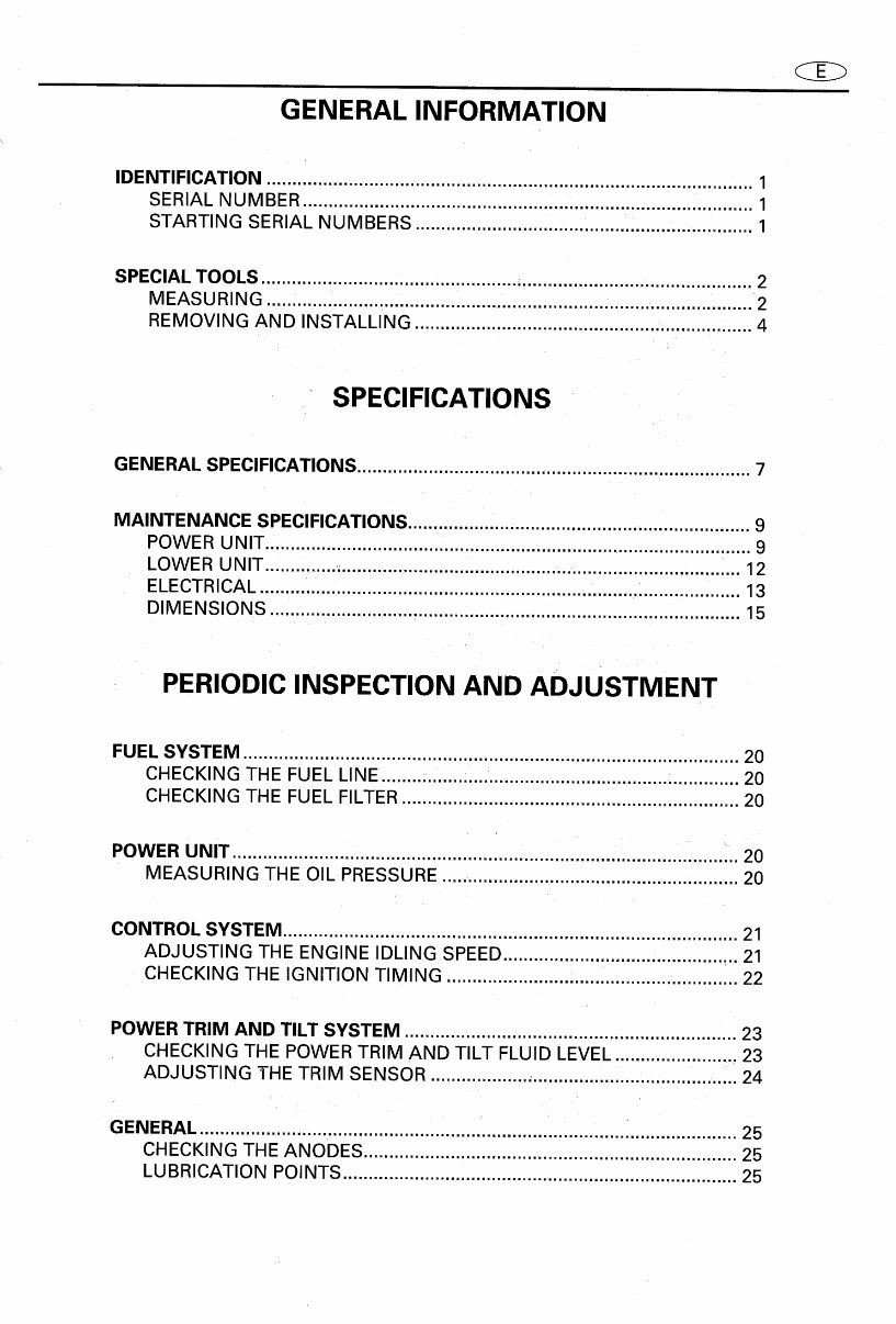
GENERAL INFORMATION IDENTIFICATION ............................................................................................... 1 SERIAL NUMBER ........................................................................................ 1 STARTING SERIAL NUMBERS .................................................................. 1 SPECIALTOOLS ................................................................................................ 2 MEASURING ........................................................................................... 2 REMOVING AND INSTALLING .................................................................. 4 SPECIFICATIONS , GENERAL SPECIFICATIONS ............................................................................. 7 MAINTENANCE SPECIFICATIONS ....................................................................9 POWER UNIT ............................................................................................... 9 LOWER UNIT .............................................................................................. 12 ELECTRICAL .............................................................................................. 13 DIMENSIONS ............................................................................................ 15 PERIODICINSPECTION AND ADJUSTMENT FUEL SYSTEM ............................................................................................. 20 CHECKING THE FUEL LINE ...................................................................... 20 CHECKING THE FUEL FILTER.................................................................. 20 POWER UNIT ................................................................................................... 20 MEASURING THE OIL PRESSURE.......................................................... 20 CONTROL SYSTEM......................................................................................... 21 ADJUSTING THE ENGINE IDLING SPEED.... 21 CHECKING THE IGNITION TIMING • 22 POWER TRIM AND TILT SYSTEM ................................................................. 23 CHECKING THE POWER TRIM AND TILT FLUID LEVEL.......................... 23 ADJUSTING THE TRIM SENSOR ...................,........................................ 24 GENERAL............................................. ..' ...... '_. ..................... ,..... i ...... ' .............. 25 CHECKING THE ANODES ......................................................................... 25 LUBRICATION POINTS ............................................................................. 25
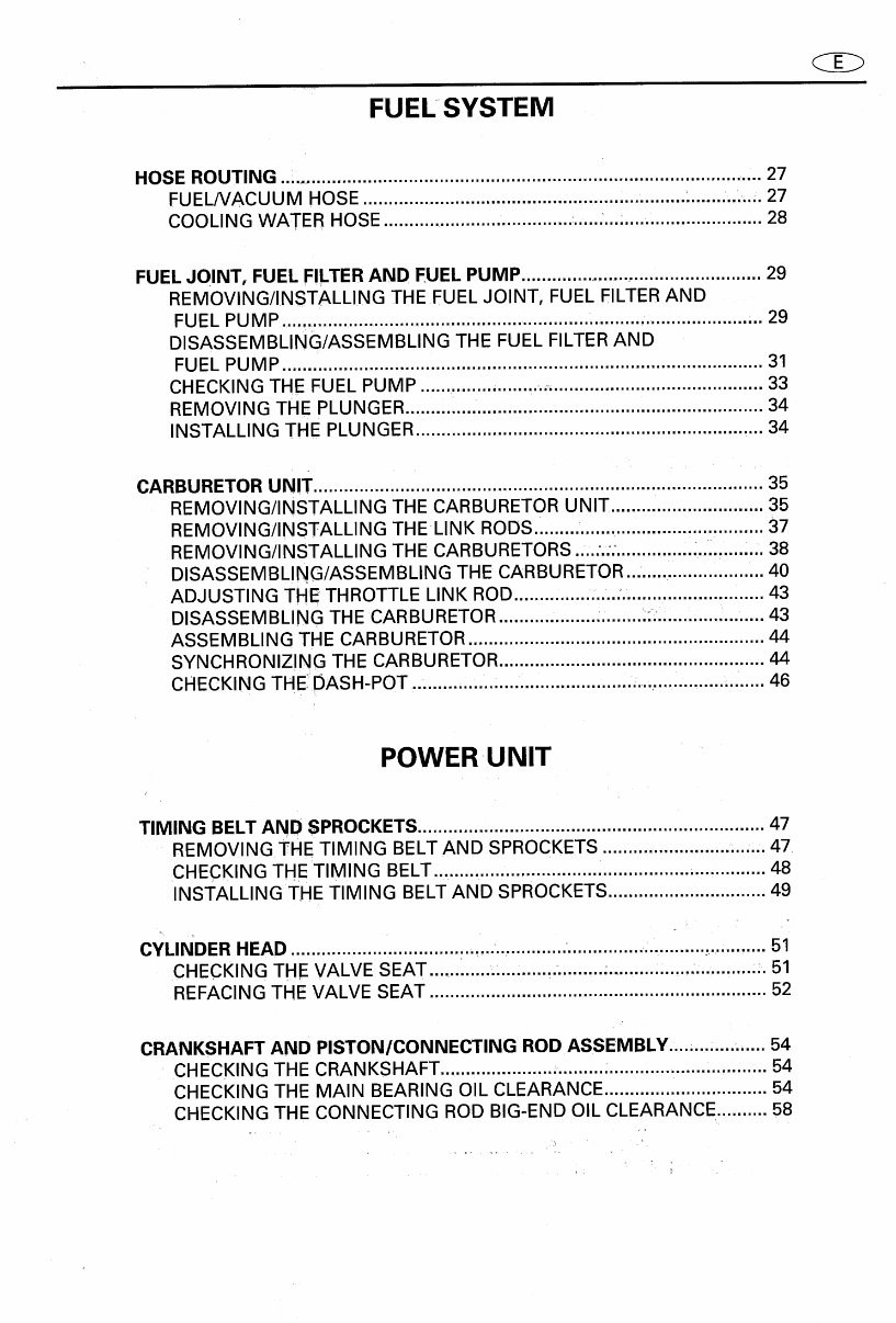
FUEL SYSTEM HOSE ROUTING ................... 27 FUEL/VACUUM HOSE .................................................. ' ............ ,.:...,. 27 COOLING WATER HOSE....................................: ..................................... 28 FUEL JOINT, FUEL FILTERAND FUEL PUMP................................................. 29 REMOVING/INSTALLING THEFUEL JOINT, FUEL FILTERAND FUEL PUMP ............................... .......... 29 DISASSEMBLING/ASSEMBLING THE FUEL FILTERAND FUEL PUMP .............................................................................................. 31 CHECKING THE FUEL PUMP ................ ,...... ,...,. ......................................... 33 REMOVING THE PLUNGER ...... • ................ 34 INSTALLING THE PLUNGER .................................................................... 34 CARBURETORUNIT ........................................................................................ 35 REMOVING/INSTALLING THE CARBURETORUNIT .............................. 35 REMOVING/INSTALLING THELINK RODS.. _ ...,.............. 37 REMOVING/INSTALLING THE CARBURETORS ...... 38 DISASSEMBLING/ASSEMBLING THE CARBURETOR 40 ADJUSTING THE THROTTLE LINK ROD............. .......:.. .......................... 43 DISASSEMBLING THE CARBURETOR................... ......... :::......., ..... ..: ..... 43 ASSEMBLING THE CARBURETOR.......................................................... 44 SYNCHRONIZING THE CARBURETOR .................................................... 44 CHECKING THE DASH-POT .:....... ,..,...,:...,..................... .... .. ,..., ....... 46 POWER UNIT TIMING BELT AND SPROCKETS ..................................................................... 47 REMOVING THE TIMING BELT AND SPROCKETS......................... ,...... 47 CHECKINGTHE TIMING BELT... ............................................... ,.............. 48 INSTALLING THE TIMING BELT AND SPROCKETS ............................... 49 : cYLINDER HEAD .51 CHECKING THE VALVE SEAT..., ......... ........... ,:,.,...,... ..... • ....,:.....:, ...... ,.... ,:. 51 REFACINGTHE VALVE SEAT .................................................................. 52 CRANKSHAFTAND PISTON/CONNECTING ROD ASSEMBLY ..... .,..... 54 CHECKINGTHE CRANKSHAFT ................... ,.,.. ....... .: ............................ ,.. 54 CHECKINGTHE MAIN BEARING OIL CLEARANCE ................................ 54 CHECKINGTHECONNECTINGROD BIG-END OIL CLEARANCE .......... 58 4
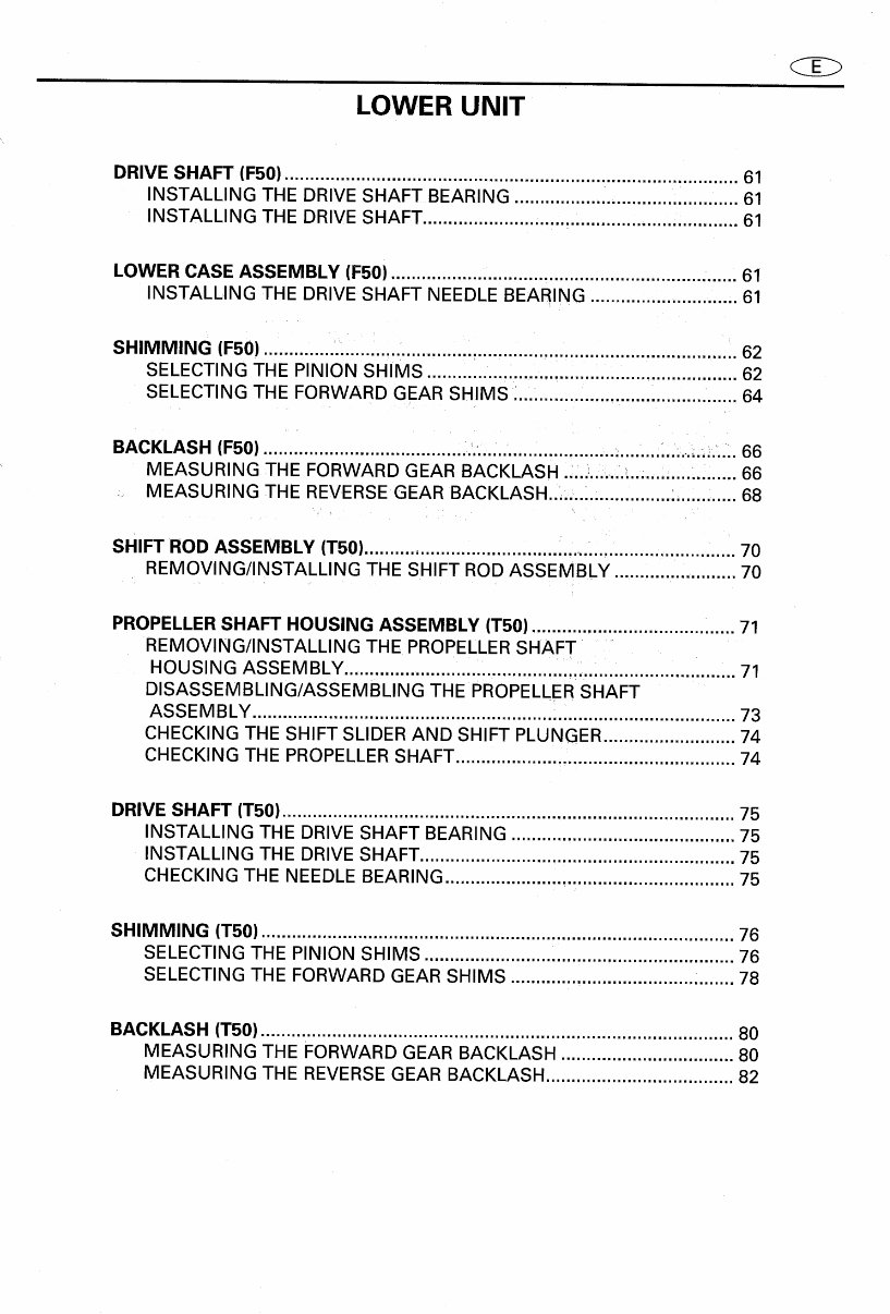
LOWER UNIT DRIVE SHAFT (F50) ......................................................................................... 61 INSTALLING THE DRIVE SHAFT BEARING ................. .............. .i ........... 61 INSTALLING THE DRIVE SHAFT...................... ; ....... ,,.................. ;. ........... 61 LOWER CASE ASSEMBLY (F50) .................................................................... 61 INSTALLING THE DRIVE SHAFT NEEDLE BEARING ............................. 61 SHIMMING (F50) ............................................................................................. 62 SELECTINGTHE PINION SHIMS .............................................................. 62 SELECTING THE FORWARD GEAR SHIMS ............................................ 64 BACKLASH (F50) ......................................... • .............................................. ;...... 66 _ MEASURING THE FORWARD GEAR BACKLASH .................................. 66 MEASURING THE REVERSEGEAR BACKLASH....... _ ................:............ 68 SHIFT ROD ASSEMBLY(T50)......................................................................... 70 REMOVING/INSTALLING THE SHIFT ROD ASSEMBLY ........................ 70 PROPELLERSHAFTHOUSING ASSEMBLY (T50) ................................... i ..... 71 REMOVING/INSTALLING THE PROPELLERSHAFT ...... HOUSING ASSEMBLY. 71 DISASSEMBLING/ASSEMBLING THE PROPELLERSHAFT ASSEMBLY ........................................................... :................................... 73 CHECKING THE SHIFT SLIDER AND SHIFT PLUNGER.......................... 74 CHECKING THE PROPELLERSHAFT ....................................................... 74 DRIVE SHAFT (T50) ......................................................................................... 75 INSTALLING THE DRIVE SHAFT BEARING ........... ,................................ 75 INSTALLING THE DRIVE SHAFT .............................................................. 75 CHECKINGTHE NEEDLE BEARING......................................................... 75 SHIMMING (T50) ............................................................................................. 76 SELECTING THE PINION SHIMS ......................... ,................................... 76 SELECTING THE FORWARD GEAR SHIMS .............,......................: ....... 78 BACKLASH (T50) ............................................................................................. 80 MEASURING THE FORWARD GEAR BACKLASH.................................. 80 MEASURING THE REVERSEGEAR BACKLASH ..................................... 82
BRACKETUNIT POWER TRIM AND TILT UNIT ...... 83 REMOVING/INSTALLING THE POWER TRIM AND TILT UNIT .... ... 83 REMOVING THE POWER TRIM AND TILT UNIT. .................i .............i... 85 TILT CYLINDERASSEMBLY AND GEAR PUMP 86 REMOVING/INSTALLING THE TILT CYLINDER ASSEMBLY AND GEAR PUMP ............................................................................................. 86 DISASSEMBLING/ASSEMBLING THE TILT ROD ASSEMBLY1............ 87 DISASSEMBLING/ASSEMBLING THE TILT ROD ASSEMBLY 2 ........ 89 REMOVING THECYLINDER END SCREW _ 92 CHECKING THE OUTER CYLINDEREND SCREW .................................. 92 CHECKING THE TILT ROD........................................................................ 92 CHECKING THE OUTER CYLINDER.. ' 93 CHECKING THE PISTONS ................................ _.., ................:.:...... :._ ........... 93 INSTALLING THE INNER CYLINDER ASSEMBLY 93 INSTALLING THE OUTER CYLINDER ASSEMBLY ................................. 93 FILLING THE RESERVOIR ............................................... ......................... 94 BLEEDINGTHE POWER TRIM AND TILT UNIT (UNINSTALLED).. 94 BLEEDINGTHE POWER TRIMAND TILT UNIT (BUILT-IN) 96 GEAR PUMP 97 DISASSEMBLING/ASSEMBLING THE GEAR PUMP 1 ........................... 97 DISASSEMBLING/ASSEMBLING THE GEAR PUMP 2 99 F
No software or crap you need to load, plain simple easy to use PDFs only.
GearHead Manuals is your only source for repair, service, and shop manual PDFs.
Our repair manual, owner's manuals, and parts catalogs PDFs contain all information you'll need to perform repairs, look up parts, or do routine maintenance on your machine. You will have access to information regarding the following topics:
General Information
Routine Maintenance
Engine Removal and Installation
Fuel System
Lubrication and Cooling System
Engine Specifications
Transmission, Drive Chain & Sprockets
Steering System
Shocks
Body Work
Intake & Exhaust
Electrical System
Advanced Troubleshooting
And more!
With our downloadable repair manual PDFs, find the page pertaining to your job, print it off, and get working on your machine. No more ruining your expensive paper shop manual with grease and dirt.
Broken down on the trail or site and have a smartphone? What an easy way to find your problem and repair it on the spot, no downtime on the job site. With our downloadable repair manual PDFs, you instantly have access to the material needed to get you running again. Kind of tough to do that with a paper manual.
All our repair manual PDFs come with a Lifetime Protection Policy. If lost or damaged, simply contact us, and we'll replace it free of charge for life.
We provide various repair service manuals, workshop manuals, repair manuals, owners manuals, parts catalogs, and other various PDFs.
All in an electronic PDF format.
UTVs, motorcycles, ATVs, quads, snowmobiles, Seadoos, equipment, small engines, inboards, outboards, and more.
Instant download
No shipping cost with a PDF
Get a PDF so no waiting, repair it now
If you are looking for a specific manual and cannot find it or do not see it listed, then contact our customer support team via the CONTACT US LINK ABOVE with details of the required manual, and we will do our absolute best to find and list it for you.