HOW TO USE THIS MANUAL MANUAL FORMAT All of the procedures in this manual are organized in a sequential, step-by-step format. The information has been complied to provide the mechanic with an easy to read, handy refer- ence that contains comprehensive explanations of all disassembly, repair, assembly, and in- spection operations. In this revised format, the condition of a faulty component will precede an arrow symbol and the course of action required will follow the symbol, e.g., 8 Bearings Pitting/Scratches fi Replace. To assist you to find your way through this manual, the section title and major heading is given at the top of every page. ILLUSTRATIONS The illustrations within this service manual represent all of the designated models. CROSS REFERENCE The cross references have been kept to a minimum. Cross references will direct you to the appropriate section or chapter. E
MODE D’UTILISA- TION DU MANUEL PRESENTATION DU MANUEL Dans ce manuel, tous les procédés sont décrits pas à pas. Les informations ont été condensées pour fournir au mécani- cien un guide pratique et facile à lire, contenant des explications claires pour tous les procédés de démontage, répa- ration, remontage et vérification. Dans ce nouveau format, l’état d’un composant défectueux est suivi d’une flèche qui indique les mesures à prendre. Exemple: 9 Roulements Piqûres/Endommagement fi Changer. Pour plus de facilité, le titre de cha- pitre ainsi que le titre de section sont repris en tête de chaque page. ILLUSTRATIONS Les illustrations contenues dans ce ma- nuel de service représentent tous les modèles concernés. REFERENCES CROISEES Les références ont été réduites à un mi- nimum. Les références croisées vous renvoient directement à la section ou au chapitre approprié. LEITFADEN FÜR DIESES HANDBUCH AUFBAU DES HANDBUCHS Dieses Handbuch enthält Beschrei- bungen von Arbeitsverfahren, die für Demontage, Reparatur, Monta- ge, Einstellung und Inspektion ein- gesetzt werden. Alle Arbeiten wer- den der Reihe nach schrittweise dargestellt. Der geänderte Aufbau gibt den Zu- stand eines schadhaften Bauteils vor einem Pfeilsymbol an. Die erfor- derlichen Maßnahmen werden nach dem Symbol beschrieben, z.B: 9 Lager Lochfraß/Beschädigung fi Ersetzen. Um Ihnen das Auffinden von ge- wünschten Stellen in dem Hand- buch zu erleichtern, ist oben auf je- der Seite der Titel des Kapitels und betreffenden Abschnitts aufgeführt. ABBILDUNGEN Die Abbildungen in diesem Kun- dendiensthandbuch beziehen sich auf alle Modelle. QUERVERWEISE Querverweise sind auf ein Mindest- maß begrenzt. Sie führen Sie zum entsprechenden Abschnitt oder Ka- pitel. COMO UTILIZAR ESTE MANUAL FORMATO DEL MANUAL Todos los procedimientos de este ma- nual están preparados en un formato secuencial de paso a paso. La información ha sido compilada para ofrecer al mecánico una referencia útil y de fácil lectura que contiene amplias explicaciones de todos los procedi- mientos de desmontaje, reparación, montaje, e inspecciones. En este formato revisado, la condición de un componente averiado irá prece- dida de un símbolo de flecha y el curso de la acción requerida seguirá al sím- bolo, como por ejemplo: 9 Cojinetes Picaduras/Daños fi Reemplazar. Para ayudarle a orientarse a través de este manual, en la parte superior de cada página figuran el título de la sección y el encabezamiento principal. FIGURAS Las figuras que aparecen en este ma- nual de servicio representan todos los modelos designados. REFERENCIAS CRUZADAS Las referencias cruzadas se han reduci- do al mínimo y le dirigen al apartado o capítulo correcto. D F ES
IMPORTANT INFORMATION In this Service Manual particularly important information is distinguished in the following ways. Q The Safety Alert Symbol means ATTENTION! BECOME ALERT! YOUR SAFETY IS INVOLVED! w Failure to follow WARNING instructions could result in severe injury or death to the machine operator, a bystander, or a person inspecting or repairing the outboard motor. cC A CAUTION indicates special precautions that must be taken to avoid damage to the out- board motor. NOTE: A NOTE provides key information to make procedures easier or clearer. E
F INFORMATIONS IMPORTANTES Les informations plus particulièrement importantes présentées dans ce manuel de service sont mises en évidence de la façon sui- vante. Q Ce symbole signale un danger : ATTENTION DANGER ! SOYEZ ATTENTIF ! VOTRE SECURITE EST EN JEU ! XG Le respect des consignes AVERTISSEMENT est impératif, faute de quoi le conducteur, toute personne se trouvant à proximité ou le personnel chargé de l’entretien du moteur hors-bord risquerait d’être grièvement voire mortellement bles- sé. fF ATTENTION indique les consignes qui doivent être respectées afin d’éviter d’endommager le moteur hors-bord. N.B.: N.B. donne des informations importantes qui facilitent et expliquent les différentes opérations.
WICHTIGER HINWEIS In diesem Kundendiensthandbuch werden wichtige Hinweise folgendermaßen hervorgehoben. Q Das Achtungsschild bedeutet: ACHTUNG! AUFGEPASST! ES GEHT UM IHRE SICHERHEIT! W Ein Nichtbefolgen der Warnhinweise kann ernsthafte Verletzungen und sogar den Tod zur Folge haben. Dies gilt für Be- diener, Zuschauer und am Motor arbeitende Techniker gleichermaßen. dD DUnter dieser Überschrift ergehen Hinweise auf Vorsichtsmaßnahmen zum Schutze des Motors. HINWEIS: Hier geht es um nützliche Tips und Hinweise. D
ES INFORMACION IMPORTANTE En este manual de servicio, la información especialmente importante se distingue de las siguientes maneras. Q El símbolo de seguridad significa ¡ATENCION! ¡PERMANEZCA ALERTA! ¡SU SEGURIDAD ESTA EN JUEGO! r La no observancia de las instrucciones contenidas en un AVISO puede provocar graves lesiones o incluso la muerte del operador del motor fuera borda, de las personas que se encuentren a su alrededor o de la persona que inspeccione o repare el motor fuera borda. bB Una PRECAUCION indica cuidados especiales que deben tomarse para evitar dañar el motor fuera borda. NOTA: Una NOTA ofrece información clave para facilitar o aclarar los procedimientos.
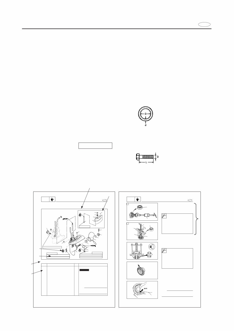
HOW TO USE THIS MANUAL 1 To help identify parts and clarify procedure steps, there are exploded diagrams at the start of each removal and disassembly section. 2 Numbers are given in the order of the jobs in the exploded diagram. A circled number indicates a disassembly step. 3 Symbols indicate parts to be lubricated or replaced (see “SYMBOLS”). 4 A job instruction chart accompanies the exploded diagram, providing the order of jobs, names of parts, notes in jobs, etc. Example: O-ring size 39.5 x 2.5 mm: Inside diameter (D) x ring diameter (d) 5 Dimension figures and the number of parts, are provided for fasteners that require a tightening torque: Example: Bolt or screw size 10 x 25 mm (2) : M10(D) x 25 mm (L) (2pieces) 6 Jobs requiring more information (such as special tools and technical data) are described sequentially. E E LOWER UNIT LOWR LOWER UNIT EXPLODED DIAGRAM zFor long 9 10 14 11 12 5 4 3 2 1 8 7 6 10 Nm (1.0 m•kg, 7.2 ft•lb) 11 13 17 16 15 M6 x 40 mm M6 x 167 mm 15 M6 x 16 mm 14 1st 3 Nm (0.3 m•kg, 2.17 ft•lb) 2nd 8 Nm (0.8 m•kg, 5.8 ft•lb) 1st 3 Nm (0.3 m•kg, 2.17 ft•lb) 2nd 8 Nm (0.8 m•kg, 5.8 ft•lb) 6-1 REMOVAL AND INSTALLATION CHART Step 1 2 3 4 5 6 7 8 9 10 Q’ty 1 1 1 1 1 1 1 1 1 1 Service points Follow the left “Step” for removal. NOTE Set the shift lever to reverse position and loosen the bolt (shift rod connec- tor). Not reusable Procedure/Part name LOWER UNIT REMOVAL Cotter pin Propeller nut Washer Propeller Spacer Bolt (anode) Toothed washer (anode) Anode Grommet Bolt (shift rod connector) Lower casing cap oil seal removal 1. Remove: 9Oil seals 1 Lower casing cap/Propeller shaft bearing removal 1. Remove: Ball bearing 1 A For USA and CANADA B Except for USA and CANADA E LOWER CASING CAP ASS’Y LOWR 1 2 3 4 1 6 5 1 6-12 Slide hammer set 2: YB-06096 Stopper guide plate 3: 90890-06501 Bearing puller 4: 90890-06535 Bearing puller craw 5: 90890-06537 Stopper guide stand 6: 90890-06538 Slide hammer set: YB-06096 Stopper guide plate: 90890-06501 Bearing puller: 90890-06535 Bearing puller craw: 90890-06537 Stopper guide stand: 90890-06538 SERVICE POINTS Gears inspection 1. Inspect: 9Tooth 9Dog Wear/Damage fi Replace. Bearings inspection 1. Inspect: 9Bearing Pitting/Rumbling fi Replace. NOTE: Turn the bearing by fingers and check the bearing pitching A B 3 4 5 6 2 1 2 9 9 9 9 9
This Service Repair Manual for the Yamaha F4A, F4 Outboard is a comprehensive guide with high-quality diagrams and instructions for servicing and repairing your outboard. It is suitable for both professional mechanics and DIY enthusiasts. The manual covers general information, specifications, periodic inspection and adjustment, fuel system, power unit, lower unit, bracket unit, electrical system, and trouble analysis.
It is compatible with all versions of Windows and Mac, and the language used is English. The file format is PDF, and it requires Adobe Reader. The manual is printable, allowing you to take the necessary pages with you to the garage or workshop. By following the step-by-step instructions, you can save money by performing your own repairs. There are no shipping costs or waiting for a CD to arrive as the manual is available for instant download upon secure payment processing.